warning light SUBARU IMPREZA WRX 2013 4.G Owner's Manual
[x] Cancel search | Manufacturer: SUBARU, Model Year: 2013, Model line: IMPREZA WRX, Model: SUBARU IMPREZA WRX 2013 4.GPages: 414, PDF Size: 14.23 MB
Page 83 of 414
1-56Seat, seatbelt and SRS airbags
The following components are monitored
by the indicator: .Front sub sensor
– Right-hand side
– Left-hand side
. Airbag control module (including im-
pact sensors). Frontal airbag module
– Driver ’s side
– Front passenger ’s side
. Side airbag sensor
– Center pillar right-hand side
– Center pillar left-hand side
. Side airbag module
– Driver ’s side
– Front passenger ’s side
. Curtain airbag sensor
– Rear wheel house right-hand side
– Rear wheel house left-hand side
. Curtain airbag module
– Right-hand side
– Left-hand side
. Satellite safing sensor (under the rear
center seat). Seatbelt pretensioner
– Driver ’s side
– Front passenger ’s side
. Seatbelt buckle switch (front passen-
ger ’s side)
. Front passenger ’s seatbelt tension sensor.
Front passenger ’s occupant detection
system weight sensor. Front passenger ’s occupant detection
control module. Front passenger ’s frontal airbag ON
and OFF indicator. All related wiring
WARNING
If the warning light exhibits any of
the following conditions, there may
be a malfunction in the seatbelt
pretensioners and/or SRS airbag
system. Immediately take your vehi-
cle to your nearest SUBARU dealer
to have the system checked. Unless
checked and properly repaired, the
seatbelt pretensioners and/or SRS
airbag will not operate properly in
the event of a collision, which may
increase the risk of injury. . Flashing or flickering of the warn-
ing light
. No illumination of the warning
light when the ignition switch is
first turned to the “ON ”position
. Continuous illumination of the
warning light
. Illumination of the warning light while driving
& SRS airbag system servicing
WARNING
. When discarding an airbag mod-
ule or scrapping the entire vehi-
cle damaged by a collision, con-
sult your SUBARU dealer.
. The SRS airbag has no user-
serviceable parts. Do not use
electrical test equipment on any
circuit related to the SRS airbag
system. For required servicing of
the SRS airbag, consult your
nearest SUBARU dealer. Tamper-
ing with or disconnecting thesystem ’s wiring could result in
accidental inflation of the SRS
airbag or could make the system
inoperative, which may result in
serious injury.
CAUTION
If you need service or repair in areas
indicated in the following list, have
the work performed by an author-
ized SUBARU dealer. The SRS air-
Page 90 of 414
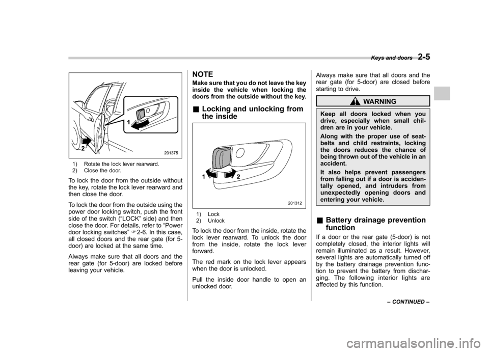
1) Rotate the lock lever rearward.
2) Close the door.
To lock the door from the outside without
the key, rotate the lock lever rearward and
then close the door.
To lock the door from the outside using the
power door locking switch, push the front
side of the switch ( “LOCK ”side) and then
close the door. For details, refer to “Power
door locking switches ”F 2-6. In this case,
all closed doors and the rear gate (for 5-
door) are locked at the same time.
Always make sure that all doors and the
rear gate (for 5-door) are locked before
leaving your vehicle. NOTE
Make sure that you do not leave the key
inside the vehicle when locking the
doors from the outside without the key. &
Locking and unlocking from
the inside
1) Lock
2) Unlock
To lock the door from the inside, rotate the
lock lever rearward. To unlock the door
from the inside, rotate the lock leverforward.
The red mark on the lock lever appears
when the door is unlocked.
Pull the inside door handle to open an
unlocked door. Always make sure that all doors and the
rear gate (for 5-door) are closed before
starting to drive.
WARNING
Keep all doors locked when you
drive, especially when small chil-
dren are in your vehicle.
Along with the proper use of seat-
belts and child restraints, locking
the doors reduces the chance of
being thrown out of the vehicle in anaccident.
It also helps prevent passengers
from falling out if a door is acciden-
tally opened, and intruders from
unexpectedly opening doors and
entering your vehicle.
& Battery drainage prevention function
If a door or the rear gate (5-door) is not
completely closed, the interior lights will
remain illuminated as a result. However,
several lights are automatically turned off
by the battery drainage prevention func-
tion to prevent the battery from dischar-
ging. The following interior lights are
affected by this function. Keys and doors
2-5
– CONTINUED –
Page 108 of 414
!Initialization of power window
If the vehicle ’s battery is disconnected due
to situations such as battery or fuse
replacement, the following functions aredeactivated. . One-touch auto up/down function
. Anti-entrapment function
Initialize the power window using the
following procedure to reactivate thesefunctions.
1. Close the driver ’s door.
2. Turn the ignition switch to the “ON ”
position.
3. Open the driver ’s side window halfway
by pushing down the power window switch.
4. Pull up the power window switch and
close the window completely. Continue
pulling up the switch for approximately 1
second after the window is closed com-
pletely. Trunk lid (4-door)
WARNING
. To prevent dangerous exhaust
gas from entering the vehicle,
always keep the trunk lid closed
while driving.
. Help prevent children, adults or
animals from locking themselves
in the trunk. On hot or sunny
days, the temperature in the
trunk could quickly become high
enough to cause death or serious
heat-related injuries including
brain damage to anyone locked
inside, particularly for small chil-dren.
. When leaving the vehicle, either
close all windows and lock all
doors. Also make certain that the
trunk is closed. &
To open and close the trunk
lid from outside
The trunk lid can be opened using the
remote keyless entry system. Refer to“ Remote keyless entry system ”F 2-7.
To close the trunk lid, lightly press the
trunk lid down until the latch engages.
NOTE
Do not leave your valuables in the
trunk when you leave your vehicle. & To open the trunk lid from inside
Pull the trunk lid release lever upward. Keys and doors
2-23
– CONTINUED –
Page 109 of 414
2-24Keys and doors
&To lock and unlock the trunk
lid release lever
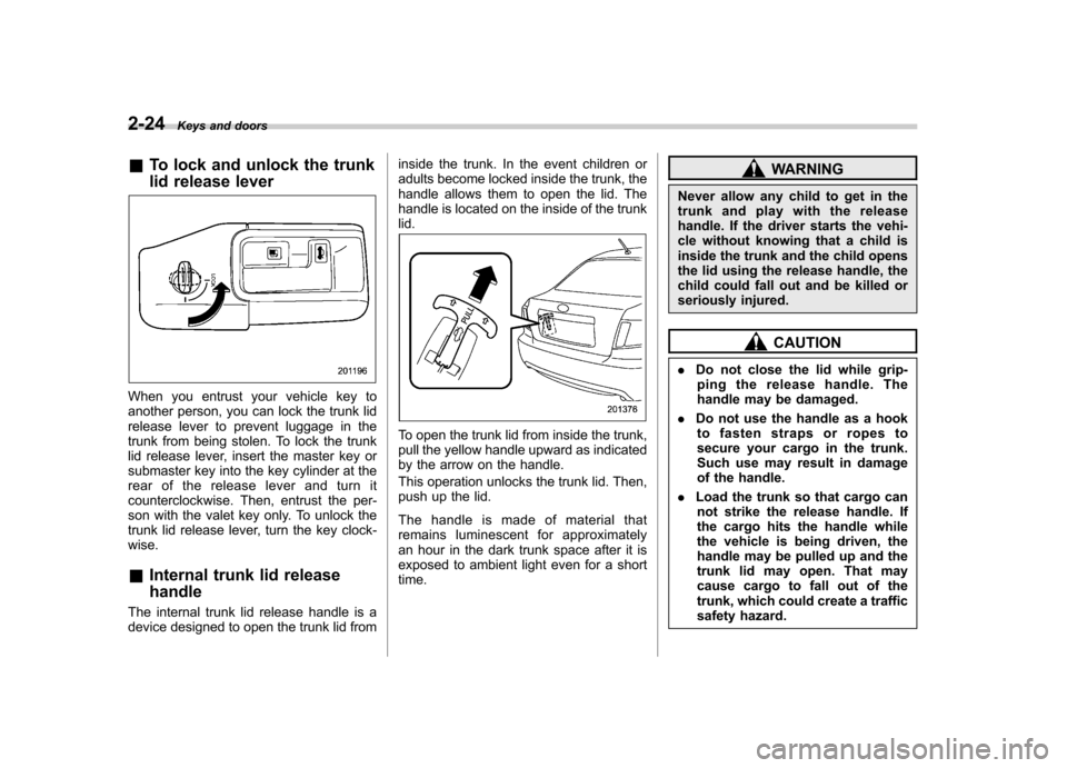
When you entrust your vehicle key to
another person, you can lock the trunk lid
release lever to prevent luggage in the
trunk from being stolen. To lock the trunk
lid release lever, insert the master key or
submaster key into the key cylinder at the
rear of the release lever and turn it
counterclockwise. Then, entrust the per-
son with the valet key only. To unlock the
trunk lid release lever, turn the key clock-wise. &Internal trunk lid release handle
The internal trunk lid release handle is a
device designed to open the trunk lid from inside the trunk. In the event children or
adults become locked inside the trunk, the
handle allows them to open the lid. The
handle is located on the inside of the trunklid.
To open the trunk lid from inside the trunk,
pull the yellow handle upward as indicated
by the arrow on the handle.
This operation unlocks the trunk lid. Then,
push up the lid.
The handle is made of material that
remains luminescent for approximately
an hour in the dark trunk space after it is
exposed to ambient light even for a shorttime.
WARNING
Never allow any child to get in the
trunk and play with the release
handle. If the driver starts the vehi-
cle without knowing that a child is
inside the trunk and the child opens
the lid using the release handle, the
child could fall out and be killed or
seriously injured.
CAUTION
. Do not close the lid while grip-
ping the release handle. The
handle may be damaged.
. Do not use the handle as a hook
to fasten straps or ropes to
secure your cargo in the trunk.
Such use may result in damage
of the handle.
. Load the trunk so that cargo can
not strike the release handle. If
the cargo hits the handle while
the vehicle is being driven, the
handle may be pulled up and the
trunk lid may open. That may
cause cargo to fall out of the
trunk, which could create a traffic
safety hazard.
Page 116 of 414

Ignition switch..................................................... 3-3
LOCK .................................................................. 3-3
Acc..................................................................... 3-4
ON...................................................................... 3-4
START ................................................................ 3-4
Key reminder chime ............................................ 3-4
Ignition switch light ............................................. 3-4
Hazard warning flasher ....................................... 3-5
Meters and gauges. ............................................. 3-5
Combination meter illumination ........................... 3-5
Canceling the function for meter/gauge needle movement upon turning on the ignition switch ............................................................... 3-6
Meter/Gauge needle illumination setting (except STI) ................................................................... 3-6
Speedometer ....................................................... 3-7
Odometer/Trip meter ............................................ 3-7
Tachometer ......................................................... 3-9
Fuel gauge .......................................................... 3-9
Temperature gauge ............................................ 3-10
REV indicator light and buzzer (STI). ................ 3-10
Setting the alarm-level engine speed ................... 3-11
Deactivating the REV alarm system ..................... 3-12
Warning and indicator lights ............................. 3-12
Seatbelt warning light and chime ........................ 3-13
SRS airbag system warning light ........................ 3-14
Front passenger ’s frontal airbag ON and OFF
indicators ......................................................... 3-14
CHECK ENGINE warning light/Malfunction indicator light ................................................... 3-15 Charge warning light
.......................................... 3-16
Oil pressure warning light .................................. 3-16
Rear differential oil temperature warning light (STI) ................................................................ 3-16
Low tire pressure warning light (U.S.-spec. models) ........................................................... 3-16
ABS warning light .............................................. 3-18
Brake system warning light ................................ 3-19
Low fuel warning light ....................................... 3-20
Hill start assist warning light/Hill start assist OFF indicator light (STI) .......................................... 3-20
Door open warning light .................................... 3-20
Vehicle Dynamics Control warning light/Vehicle Dynamics Control operation indicator light .. ..... 3-20
Vehicle Dynamics Control OFF indicator light/ Traction Control OFF indicator light (STI)..... ..... 3-21
Security indicator light ....................................... 3-23
SI-DRIVE indicator light (STI) .............................. 3-23
Shift-up indicator light (STI) ............................... 3-23
Turn signal indicator lights ................................. 3-24
High beam indicator light ................................... 3-24
Cruise control indicator light .............................. 3-24
Cruise control set indicator light ........................ 3-24
Front fog light indicator light (if equipped) ..... ..... 3-24
Headlight indicator light ..................................... 3-24
Driver ’s control center differential auto indicator
light (STI) ........................................................ 3-24
Driver ’s control center differential indicator and
warning lights (STI) .......................................... 3-25
REV indicator light (STI) ..................................... 3-25
Clock .................................................................. 3-26Instruments and controls
3
Page 118 of 414
Ignition switch
WARNING
. Never turn the ignition switch to
“ LOCK ”while the vehicle is
being driven or towed because
that will lock the steering wheel,
preventing steering control. And
when the engine is turned off, it
takes a much greater effort than
usual to steer.
. Before leaving the vehicle, al-
ways remove the key from the
ignition switch for safety and
never allow an unattended child
to remain in the vehicle. Failure
to follow this procedure could
result in injury to a child or
others. Children could operate
the power windows, the moon-
roof or other controls or even
make the vehicle move.
CAUTION
Do not attach a large key holder or
key case to either key. If it banged
against your knees or hands while
you are driving, it could turn the
ignition switch from the “ON ”posi- tion to the
“Acc ”or “LOCK ”posi-
tion, thereby stopping the engine.
Also, if the key is attached to a
keyholder or to a large bunch of
other keys, centrifugal force may act
on it as the vehicle moves, resulting
in unwanted turning of the ignitionswitch.
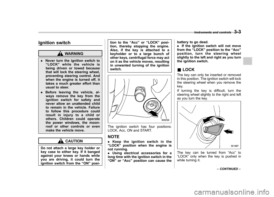
The ignition switch has four positions:
LOCK, Acc, ON and START. NOTE . Keep the ignition switch in the
“ LOCK ”position when the engine is
not running. . Using electrical accessories for a
long time with the ignition switch in the“ ON ”or “Acc ”position can cause the battery to go dead..
If the ignition switch will not move
from the “LOCK ”position to the “Acc ”
position, turn the steering wheel
slightly to the left and right as you turn
the ignition switch. & LOCK
The key can only be inserted or removed
in this position. The ignition switch will lock
the steering wheel when you remove the
key.
If turning the key is difficult, turn the
steering wheel slightly to the right and left
as you turn the key.
The key can be turned from “Acc ”to
“ LOCK ”only when the key is pushed in
while turning it. Instruments and controls
3-3
– CONTINUED –
Page 120 of 414
following conditions. .when the ignition switch is turned to the
“ ON ”position
. when all doors and the rear gate (5-
door) are locked using the remote keyless
entry transmitter Hazard warning flasher
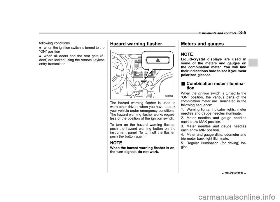
The hazard warning flasher is used to
warn other drivers when you have to park
your vehicle under emergency conditions.
The hazard warning flasher works regard-
less of the position of the ignition switch.
To turn on the hazard warning flasher,
push the hazard warning button on the
instrument panel. To turn off the flasher,
push the button again. NOTE
When the hazard warning flasher is on,
the turn signals do not work.Meters and gauges NOTE
Liquid-crystal displays are used in
some of the meters and gauges on
the combination meter. You will find
their indications hard to see if you wear
polarized glasses. &
Combination meter illumina- tion
When the ignition switch is turned to the “ ON ”position, the various parts of the
combination meter are illuminated in the
following sequence:
1. Warning lights, indicator lights, meter
needles and gauge needles illuminate.
2. Meter needles and gauge needles
each show MAX position.
3. Meter needles and gauge needles
each show MIN position.
4. Meter and gauge dials, odometer and
trip meter back light illuminate.
5. Regular illumination (for driving) be- gins. Instruments and controls
3-5
– CONTINUED –
Page 124 of 414

NOTE
If the connection between the combina-
tion meter and battery is broken for any
reason such as vehicle maintenance or
fuse replacement, the data recorded on
the trip meter will be lost. &Tachometer
The tachometer shows the engine speed
in thousands of revolutions per minute.
CAUTION
Do not operate the engine with the
pointer of the tachometer in the red
zone. This may cause severe da-
mage to the engine. &
Fuel gauge
1) Low fuel warning light (Refer to “Low fuel
warning light ”F 3-20.)
The fuel gauge shows the approximate
amount of fuel remaining in the tank.
When the ignition switch is in the “LOCK ”
or “Acc ”position, the fuel gauge shows “E ”
even if the fuel tank contains fuel.
The gauge may move slightly during
braking, turning or acceleration due to fuel
level movement in the tank.
If you press the trip knob while the ignition
switch is in the “LOCK ”or “Acc ”position,
the fuel gauge will light up and indicate the
amount of fuel remaining in the tank.
If, while the fuel gauge is indicating the
amount of fuel remaining in the tank, you
(a) do not press the trip knob for 10 seconds or (b) open and close the driver
’s
door, the fuel gauge indication will turn off.
NOTE
You will see the “”sign in the fuel
gauge meter.
This indicates that the fuel filler door
(lid) is located on the right side of thevehicle. Instruments and controls
3-9
– CONTINUED –
Page 127 of 414

3-12Instruments and controls
to OFF, OFF to ON, or the vehicle starts
moving before the setting procedure isfinished..Setting the speed is impossible
when the vehicle is moving.. The set engine speed may differ
from the engine speed shown by the
tachometer. Use the engine speed
shown by the tachometer as a roughguide.. If the setting operation is performed
with the engine switch turned off, the
REV indicator light turns off and the
setting operation is aborted when you
have stopped the setting operation for
approximately 10 seconds. . If the setting operation is performed
with the engine switch turned off, the
REV indicator light turns off and the
setting operation is aborted when you
open and close the driver ’s door.
& Deactivating the REV alarm system
To deactivate the REV indicator light and
buzzer functions of the REV alarm system,
set the thousands place of the alarm-level
engine speed to “–”. Warning and indicator lights
Several of the warning and indicator lights
illuminate momentarily and then turn off
when the ignition switch is initially turned
to the
“ON ”position. This permits check-
ing the operation of the bulbs.
Apply the parking brake and turn the
ignition switch to the “ON ”position. For
the system check, the following lights
illuminate and turn off after several sec-
onds or after the engine has started:
: Seatbelt warning light (The seatbelt warning light turns off
only when the driver fastens theseatbelt.)
: Front passenger ’s seatbelt warning
light
(The seatbelt warning light turns off
only when the front seat passenger
fastens the seatbelt.)
: SRS airbag system warning light
ON /
: Front passenger ’s frontal airbag
ON indicator light
/: Front passenger ’s frontal airbag
OFF indicator light
: CHECK ENGINE warning light/Mal- function indicator light
: Charge warning light
: Oil pressure warning light
: Rear differential oil temperature warn-ing light (STI)
: Low tire pressure warning light (U.S.- spec. models)
/: ABS warning light
/: Brake system warning light
: Low fuel warning light
: Hill start assist warning light/Hill start assist OFF indicator light (STI)
: Door open warning light
: Vehicle Dynamics Control warning light/Vehicle Dynamics Control opera-
tion indicator light
: Vehicle Dynamics Control OFF indica-tor light/Traction Control OFF indicator
light (STI)
: Cruise control indicator light
: Cruise control set indicator light
: Shift-up indicator light (STI)
: REV indicator light (STI)
:Driver ’s control center differential
indicator and warning lights (STI)
Page 128 of 414
If any lights fail to illuminate, it indicates a
burned-out bulb or a malfunction of the
corresponding system.
Consult your authorized SUBARU dealer
for repair. &Seatbelt warning light
and chime
Your vehicle is equipped with a seatbelt
warning device at the driver ’s and front
passenger ’s seat, as required by current
safety standards.
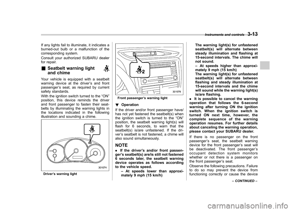
With the ignition switch turned to the “ON ”
position, this device reminds the driver
and front passenger to fasten their seat-
belts by illuminating the warning lights in
the locations indicated in the following
illustration and sounding a chime.
Driver ’s warning light
Front passenger ’s warning light
! Operation
If the driver and/or front passenger have/
has not yet fastened the seatbelt(s) when
the ignition switch is turned to the “ON ”
position, the seatbelt warning light(s) will
flash for 6 seconds, to warn that the
seatbelt(s) is/are unfastened. If the dri-ver ’s seatbelt is not fastened, a chime will
also sound simultaneously.
NOTE . If the driver ’s and/or front passen-
ger ’s seatbelt(s) are/is still not fastened
6 seconds later, the seatbelt warning
device operates as follows according
to the vehicle speed.
–At speeds lower than approxi-
mately 9 mph (15 km/h) The warning light(s) for unfastened
seatbelt(s) will alternate between
steady illumination and flashing at
15-second intervals. The chime will
not sound. –
At speeds higher than approxi-
mately 9 mph (15 km/h)
The warning light(s) for unfastened
seatbelt(s) will alternate between
flashing and steady illumination at
15-second intervals and the chime
will sound while the warning light(s)
is/are flashing.
. It is possible to cancel the warning
operation that follows the 6-second
warning after turning ON the ignition
switch. When the ignition switch is
turned ON next time, however, the
complete sequence of the warning
operation resumes. For further details
about canceling the warning operation,
please contact your SUBARU dealer.
If there is no passenger on the front passenger ’s seat, the seatbelt warning
device for the front passenger ’s seat will
be deactivated. The front passenger ’s
occupant detection system monitors
whether or not there is a passenger on
the front passenger ’s seat.
Observe the following precautions. Failure
to do so may prevent the device from
functioning correctly or cause the device Instruments and controls
3-13
– CONTINUED –