SUBARU LEGACY 1999 Service Repair Manual
LEGACY 1999
SUBARU
SUBARU
https://www.carmanualsonline.info/img/17/57435/w960_57435-0.png
SUBARU LEGACY 1999 Service Repair Manual
Trending: length, recommended oil, relay, child lock, warning light, fuel cap release, service interval
Page 291 of 1456
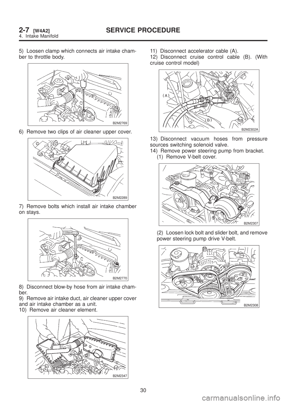
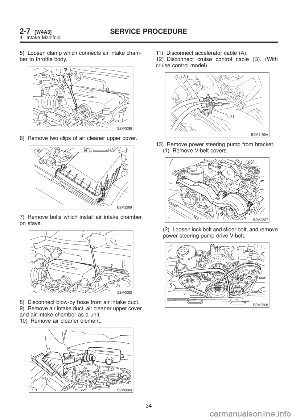
5) Loosen clamp which connects air intake cham-
ber to throttle body.
B2M2769
6) Remove two clips of air cleaner upper cover.
B2M2289
7) Remove bolts which install air intake chamber
on stays.
B2M2770
8) Disconnect blow-by hose from air intake cham-
ber.
9) Remove air intake duct, air cleaner upper cover
and air intake chamber as a unit.
10) Remove air cleaner element.
B2M2347
11) Disconnect accelerator cable (A).
12) Disconnect cruise control cable (B). (With
cruise control model)
B2M2302A
13) Disconnect vacuum hoses from pressure
sources switching solenoid valve.
14) Remove power steering pump from bracket.
(1) Remove V-belt cover.
B2M2307
(2) Loosen lock bolt and slider bolt, and remove
power steering pump drive V-belt.
B2M2308
30
2-7[W4A2]SERVICE PROCEDURE
4. Intake Manifold
Page 292 of 1456
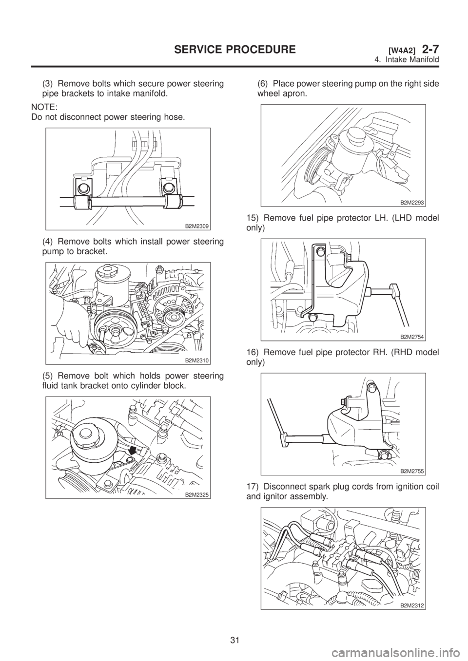
(3) Remove bolts which secure power steering
pipe brackets to intake manifold.
NOTE:
Do not disconnect power steering hose.
B2M2309
(4) Remove bolts which install power steering
pump to bracket.
B2M2310
(5) Remove bolt which holds power steering
fluid tank bracket onto cylinder block.
B2M2325
(6) Place power steering pump on the right side
wheel apron.
B2M2293
15) Remove fuel pipe protector LH. (LHD model
only)
B2M2754
16) Remove fuel pipe protector RH. (RHD model
only)
B2M2755
17) Disconnect spark plug cords from ignition coil
and ignitor assembly.
B2M2312
31
[W4A2]2-7SERVICE PROCEDURE
4. Intake Manifold
Page 293 of 1456
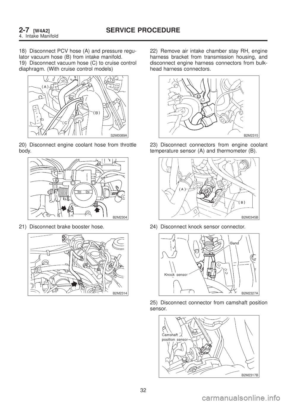
18) Disconnect PCV hose (A) and pressure regu-
lator vacuum hose (B) from intake manifold.
19) Disconnect vacuum hose (C) to cruise control
diaphragm. (With cruise control models)
S2M0089A
20) Disconnect engine coolant hose from throttle
body.
B2M2304
21) Disconnect brake booster hose.
B2M2314
22) Remove air intake chamber stay RH, engine
harness bracket from transmission housing, and
disconnect engine harness connectors from bulk-
head harness connectors.
B2M2315
23) Disconnect connectors from engine coolant
temperature sensor (A) and thermometer (B).
B2M0345B
24) Disconnect knock sensor connector.
B2M2327A
25) Disconnect connector from camshaft position
sensor.
B2M2317B
32
2-7[W4A2]SERVICE PROCEDURE
4. Intake Manifold
Page 294 of 1456
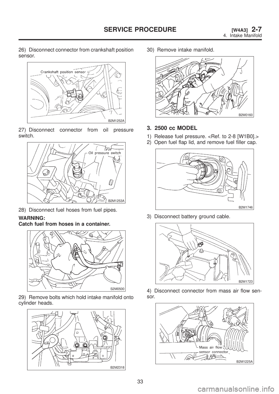
26) Disconnect connector from crankshaft position
sensor.
B2M1252A
27) Disconnect connector from oil pressure
switch.
B2M1253A
28) Disconnect fuel hoses from fuel pipes.
WARNING:
Catch fuel from hoses in a container.
S2M0500
29) Remove bolts which hold intake manifold onto
cylinder heads.
B2M2318
30) Remove intake manifold.
B2M0160
3. 2500 cc MODEL
1) Release fuel pressure.
2) Open fuel flap lid, and remove fuel filler cap.
B2M1746
3) Disconnect battery ground cable.
B2M1723
4) Disconnect connector from mass air flow sen-
sor.
B2M1225A
33
[W4A3]2-7SERVICE PROCEDURE
4. Intake Manifold
Page 295 of 1456
5) Loosen clamp which connects air intake cham-
ber to throttle body.
S2M0096
6) Remove two clips of air cleaner upper cover.
B2M2289
7) Remove bolts which install air intake chamber
on stays.
S2M0092
8) Disconnect blow-by hose from air intake duct.
9) Remove air intake duct, air cleaner upper cover
and air intake chamber as a unit.
10) Remove air cleaner element.
S2M0084
11) Disconnect accelerator cable (A).
12) Disconnect cruise control cable (B). (With
cruise control model)
B2M1190A
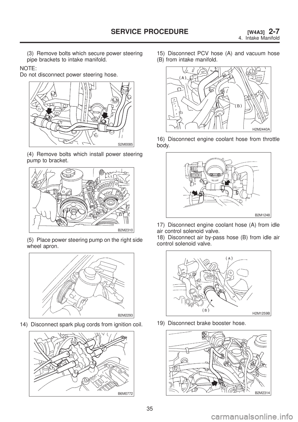
13) Remove power steering pump from bracket.
(1) Remove V-belt covers.
B2M2307
(2) Loosen lock bolt and slider bolt, and remove
power steering pump drive V-belt.
B2M2308
34
2-7[W4A3]SERVICE PROCEDURE
4. Intake Manifold
Page 296 of 1456
(3) Remove bolts which secure power steering
pipe brackets to intake manifold.
NOTE:
Do not disconnect power steering hose.
S2M0085
(4) Remove bolts which install power steering
pump to bracket.
B2M2310
(5) Place power steering pump on the right side
wheel apron.
B2M2293
14) Disconnect spark plug cords from ignition coil.
B6M0772
15) Disconnect PCV hose (A) and vacuum hose
(B) from intake manifold.
H2M2440A
16) Disconnect engine coolant hose from throttle
body.
B2M1248
17) Disconnect engine coolant hose (A) from idle
air control solenoid valve.
18) Disconnect air by-pass hose (B) from idle air
control solenoid valve.
H2M1259B
19) Disconnect brake booster hose.
B2M2314
35
[W4A3]2-7SERVICE PROCEDURE
4. Intake Manifold
Page 297 of 1456
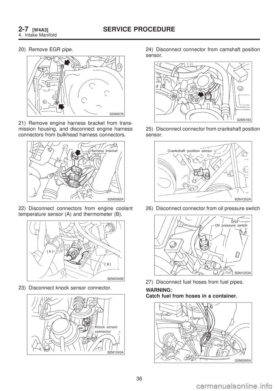
20) Remove EGR pipe.
S2M0078
21) Remove engine harness bracket from trans-
mission housing, and disconnect engine harness
connectors from bulkhead harness connectors.
S2M0082A
22) Disconnect connectors from engine coolant
temperature sensor (A) and thermometer (B).
B2M0345B
23) Disconnect knock sensor connector.
B2M1243A
24) Disconnect connector from camshaft position
sensor.
S2M0183
25) Disconnect connector from crankshaft position
sensor.
B2M1252A
26) Disconnect connector from oil pressure switch
B2M1253A
27) Disconnect fuel hoses from fuel pipes.
WARNING:
Catch fuel from hoses in a container.
S2M0090A
36
2-7[W4A3]SERVICE PROCEDURE
4. Intake Manifold
Page 298 of 1456
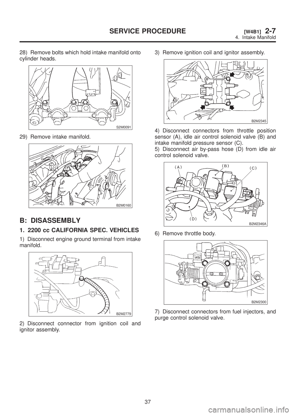
28) Remove bolts which hold intake manifold onto
cylinder heads.
S2M0091
29) Remove intake manifold.
B2M0160
B: DISASSEMBLY
1. 2200 cc CALIFORNIA SPEC. VEHICLES
1) Disconnect engine ground terminal from intake
manifold.
B2M2779
2) Disconnect connector from ignition coil and
ignitor assembly.3) Remove ignition coil and ignitor assembly.
B2M2345
4) Disconnect connectors from throttle position
sensor (A), idle air control solenoid valve (B) and
intake manifold pressure sensor (C).
5) Disconnect air by-pass hose (D) from idle air
control solenoid valve.
B2M2346A
6) Remove throttle body.
B2M2300
7) Disconnect connectors from fuel injectors, and
purge control solenoid valve.
37
[W4B1]2-7SERVICE PROCEDURE
4. Intake Manifold
Page 299 of 1456
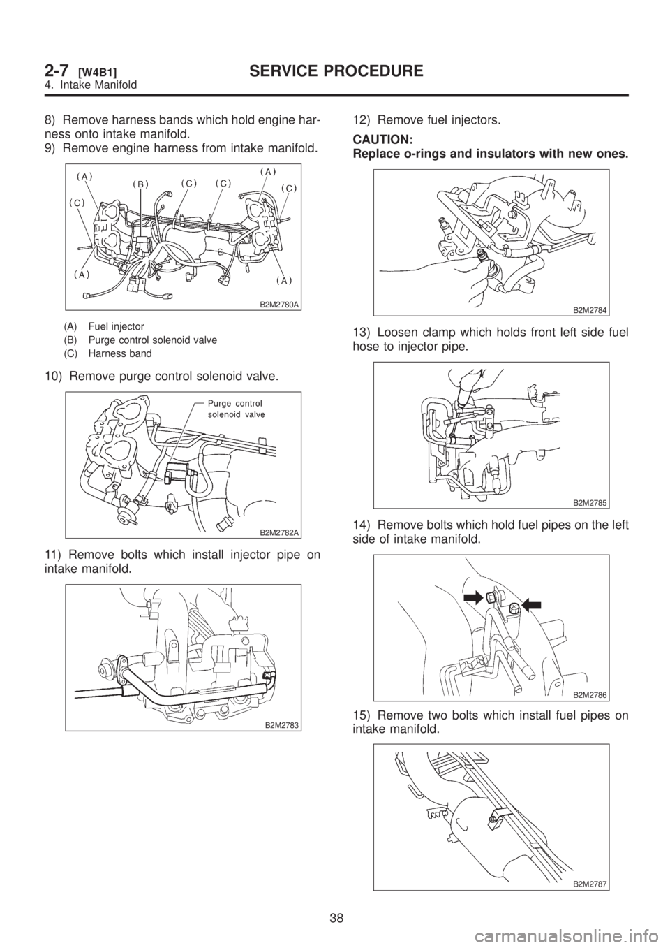
8) Remove harness bands which hold engine har-
ness onto intake manifold.
9) Remove engine harness from intake manifold.
B2M2780A
(A) Fuel injector
(B) Purge control solenoid valve
(C) Harness band
10) Remove purge control solenoid valve.
B2M2782A
11) Remove bolts which install injector pipe on
intake manifold.
B2M2783
12) Remove fuel injectors.
CAUTION:
Replace o-rings and insulators with new ones.
B2M2784
13) Loosen clamp which holds front left side fuel
hose to injector pipe.
B2M2785
14) Remove bolts which hold fuel pipes on the left
side of intake manifold.
B2M2786
15) Remove two bolts which install fuel pipes on
intake manifold.
B2M2787
38
2-7[W4B1]SERVICE PROCEDURE
4. Intake Manifold
Page 300 of 1456
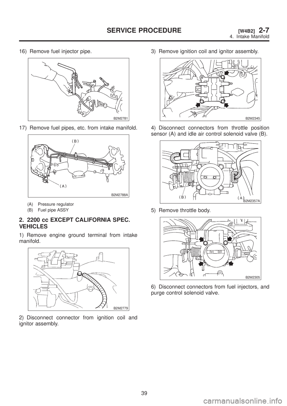
16) Remove fuel injector pipe.
B2M2781
17) Remove fuel pipes, etc. from intake manifold.
B2M2788A
(A) Pressure regulator
(B) Fuel pipe ASSY
2. 2200 cc EXCEPT CALIFORNIA SPEC.
VEHICLES
1) Remove engine ground terminal from intake
manifold.
B2M2779
2) Disconnect connector from ignition coil and
ignitor assembly.3) Remove ignition coil and ignitor assembly.
B2M2345
4) Disconnect connectors from throttle position
sensor (A) and idle air control solenoid valve (B).
B2M2357A
5) Remove throttle body.
B2M2305
6) Disconnect connectors from fuel injectors, and
purge control solenoid valve.
39
[W4B2]2-7SERVICE PROCEDURE
4. Intake Manifold
Trending: automatic transmission, trunk, transmission, charging, towing, lug pattern, ad blue
