SUBARU LEGACY 1999 Service Repair Manual
LEGACY 1999
SUBARU
SUBARU
https://www.carmanualsonline.info/img/17/57435/w960_57435-0.png
SUBARU LEGACY 1999 Service Repair Manual
Trending: compression ratio, reset, fold seats, remote control, maintenance, engine oil, coolant reservoir
Page 321 of 1456
5. Engine Coolant Temperature
Sensor
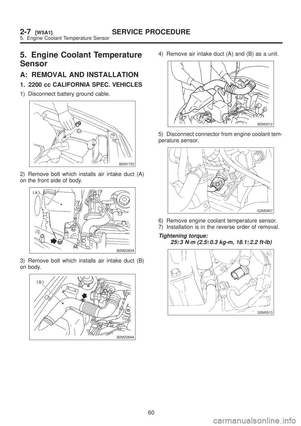
A: REMOVAL AND INSTALLATION
1. 2200 cc CALIFORNIA SPEC. VEHICLES
1) Disconnect battery ground cable.
B2M1723
2) Remove bolt which installs air intake duct (A)
on the front side of body.
B2M2283A
3) Remove bolt which installs air intake duct (B)
on body.
B2M2284A
4) Remove air intake duct (A) and (B) as a unit.
B2M2012
5) Disconnect connector from engine coolant tem-
perature sensor.
G2M0407
6) Remove engine coolant temperature sensor.
7) Installation is in the reverse order of removal.
Tightening torque:
25
±3 N´m (2.5±0.3 kg-m, 18.1±2.2 ft-lb)
S2M0513
60
2-7[W5A1]SERVICE PROCEDURE
5. Engine Coolant Temperature Sensor
Page 322 of 1456
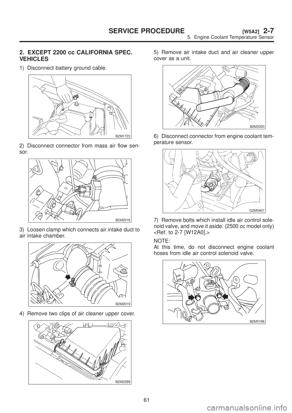
2. EXCEPT 2200 cc CALIFORNIA SPEC.
VEHICLES
1) Disconnect battery ground cable.
B2M1723
2) Disconnect connector from mass air flow sen-
sor.
B2M2018
3) Loosen clamp which connects air intake duct to
air intake chamber.
B2M2019
4) Remove two clips of air cleaner upper cover.
B2M2289
5) Remove air intake duct and air cleaner upper
cover as a unit.
B2M2020
6) Disconnect connector from engine coolant tem-
perature sensor.
G2M0407
7) Remove bolts which install idle air control sole-
noid valve, and move it aside. (2500 cc model only)
NOTE:
At this time, do not disconnect engine coolant
hoses from idle air control solenoid valve.
B2M0166
61
[W5A2]2-7SERVICE PROCEDURE
5. Engine Coolant Temperature Sensor
Page 323 of 1456
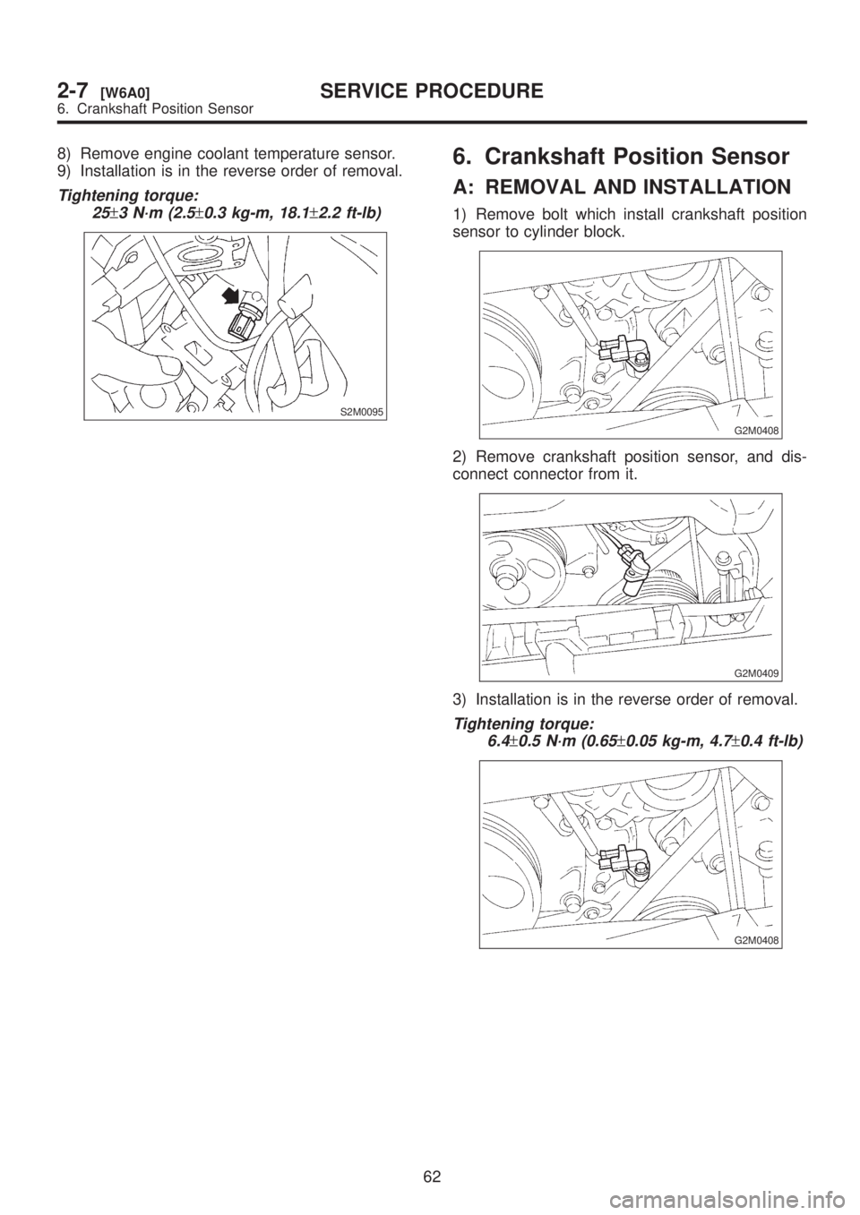
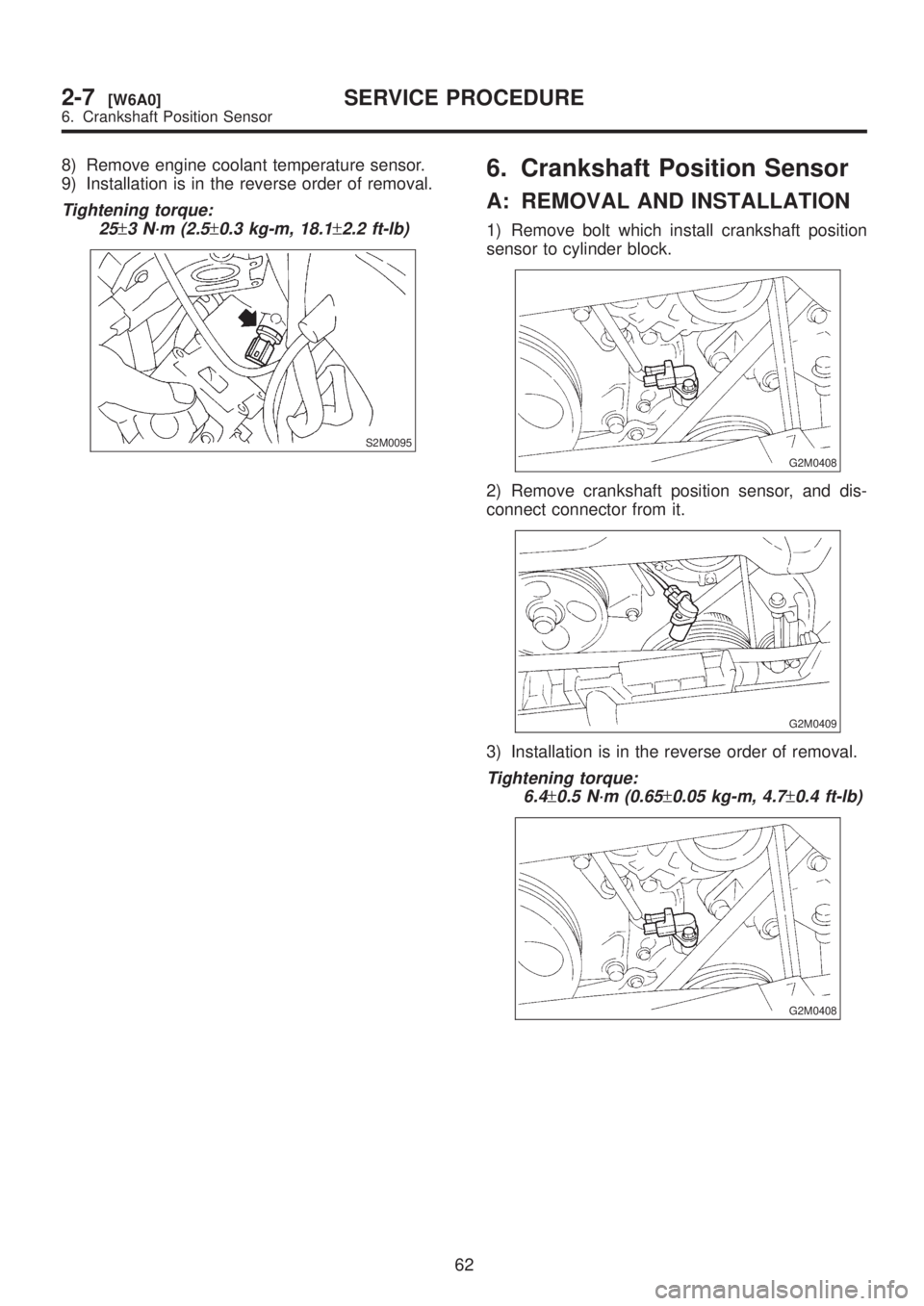
8) Remove engine coolant temperature sensor.
9) Installation is in the reverse order of removal.
Tightening torque:
25
±3 N´m (2.5±0.3 kg-m, 18.1±2.2 ft-lb)
S2M0095
6. Crankshaft Position Sensor
A: REMOVAL AND INSTALLATION
1) Remove bolt which install crankshaft position
sensor to cylinder block.
G2M0408
2) Remove crankshaft position sensor, and dis-
connect connector from it.
G2M0409
3) Installation is in the reverse order of removal.
Tightening torque:
6.4
±0.5 N´m (0.65±0.05 kg-m, 4.7±0.4 ft-lb)
G2M0408
62
2-7[W6A0]SERVICE PROCEDURE
6. Crankshaft Position Sensor
Page 324 of 1456
8) Remove engine coolant temperature sensor.
9) Installation is in the reverse order of removal.
Tightening torque:
25
±3 N´m (2.5±0.3 kg-m, 18.1±2.2 ft-lb)
S2M0095
6. Crankshaft Position Sensor
A: REMOVAL AND INSTALLATION
1) Remove bolt which install crankshaft position
sensor to cylinder block.
G2M0408
2) Remove crankshaft position sensor, and dis-
connect connector from it.
G2M0409
3) Installation is in the reverse order of removal.
Tightening torque:
6.4
±0.5 N´m (0.65±0.05 kg-m, 4.7±0.4 ft-lb)
G2M0408
62
2-7[W6A0]SERVICE PROCEDURE
6. Crankshaft Position Sensor
Page 325 of 1456
7. Front Oxygen (A/F) Sensor
A: REMOVAL
1) Disconnect battery ground cable.
B2M1723
2) Disconnect air intake duct (B). (2200 cc Califor-
nia spec. vehicles)
B2M2330A
3) Remove air intake duct. (Except 2200 cc Cali-
fornia spec. vehicles)
S2M0081
4) Disconnect connector from front oxygen sen-
sor.
B2M1979A
S2M0127A
5) Lift-up the vehicle.
6) Apply SUBARU CRC or its equivalent to
threaded portion of front oxygen (A/F) sensor, and
leave it for one minute or more.
SUBARU CRC (Part No. 004301003)
7) Remove front oxygen (A/F) sensor.
CAUTION:
When removing, do not force front oxygen
(A/F) sensor in an unnatural way especially
when exhaust pipe is cold, otherwise it will
damage exhaust pipe.
G2M0411
63
[W7A0]2-7SERVICE PROCEDURE
7. Front Oxygen (A/F) Sensor
Page 326 of 1456
B: INSTALLATION
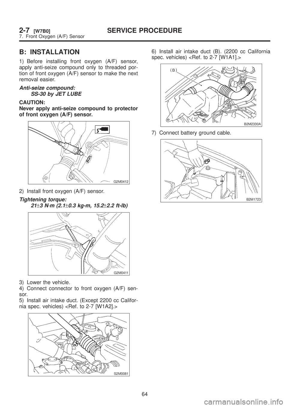
1) Before installing front oxygen (A/F) sensor,
apply anti-seize compound only to threaded por-
tion of front oxygen (A/F) sensor to make the next
removal easier.
Anti-seize compound:
SS-30 by JET LUBE
CAUTION:
Never apply anti-seize compound to protector
of front oxygen (A/F) sensor.
G2M0412
2) Install front oxygen (A/F) sensor.
Tightening torque:
21
±3 N´m (2.1±0.3 kg-m, 15.2±2.2 ft-lb)
G2M0411
3) Lower the vehicle.
4) Connect connector to front oxygen (A/F) sen-
sor.
5) Install air intake duct. (Except 2200 cc Califor-
nia spec. vehicles)
S2M0081
6) Install air intake duct (B). (2200 cc California
spec. vehicles)
B2M2330A
7) Connect battery ground cable.
B2M1723
64
2-7[W7B0]SERVICE PROCEDURE
7. Front Oxygen (A/F) Sensor
Page 327 of 1456
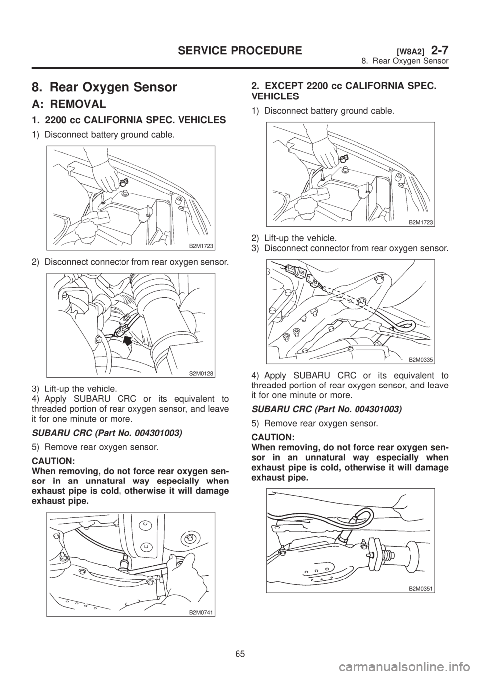
8. Rear Oxygen Sensor
A: REMOVAL
1. 2200 cc CALIFORNIA SPEC. VEHICLES
1) Disconnect battery ground cable.
B2M1723
2) Disconnect connector from rear oxygen sensor.
S2M0128
3) Lift-up the vehicle.
4) Apply SUBARU CRC or its equivalent to
threaded portion of rear oxygen sensor, and leave
it for one minute or more.
SUBARU CRC (Part No. 004301003)
5) Remove rear oxygen sensor.
CAUTION:
When removing, do not force rear oxygen sen-
sor in an unnatural way especially when
exhaust pipe is cold, otherwise it will damage
exhaust pipe.
B2M0741
2. EXCEPT 2200 cc CALIFORNIA SPEC.
VEHICLES
1) Disconnect battery ground cable.
B2M1723
2) Lift-up the vehicle.
3) Disconnect connector from rear oxygen sensor.
B2M0335
4) Apply SUBARU CRC or its equivalent to
threaded portion of rear oxygen sensor, and leave
it for one minute or more.
SUBARU CRC (Part No. 004301003)
5) Remove rear oxygen sensor.
CAUTION:
When removing, do not force rear oxygen sen-
sor in an unnatural way especially when
exhaust pipe is cold, otherwise it will damage
exhaust pipe.
B2M0351
65
[W8A2]2-7SERVICE PROCEDURE
8. Rear Oxygen Sensor
Page 328 of 1456
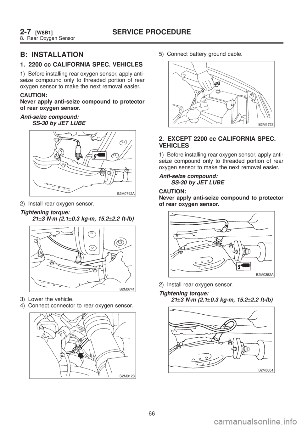
B: INSTALLATION
1. 2200 cc CALIFORNIA SPEC. VEHICLES
1) Before installing rear oxygen sensor, apply anti-
seize compound only to threaded portion of rear
oxygen sensor to make the next removal easier.
CAUTION:
Never apply anti-seize compound to protector
of rear oxygen sensor.
Anti-seize compound:
SS-30 by JET LUBE
B2M0742A
2) Install rear oxygen sensor.
Tightening torque:
21
±3 N´m (2.1±0.3 kg-m, 15.2±2.2 ft-lb)
B2M0741
3) Lower the vehicle.
4) Connect connector to rear oxygen sensor.
S2M0128
5) Connect battery ground cable.
B2M1723
2. EXCEPT 2200 cc CALIFORNIA SPEC.
VEHICLES
1) Before installing rear oxygen sensor, apply anti-
seize compound only to threaded portion of rear
oxygen sensor to make the next removal easier.
Anti-seize compound:
SS-30 by JET LUBE
CAUTION:
Never apply anti-seize compound to protector
of rear oxygen sensor.
B2M0352A
2) Install rear oxygen sensor.
Tightening torque:
21
±3 N´m (2.1±0.3 kg-m, 15.2±2.2 ft-lb)
B2M0351
66
2-7[W8B1]SERVICE PROCEDURE
8. Rear Oxygen Sensor
Page 329 of 1456
3) Connect connector to rear oxygen sensor.
B2M0335
4) Lower the vehicle.
5) Connect battery ground cable.
B2M1723
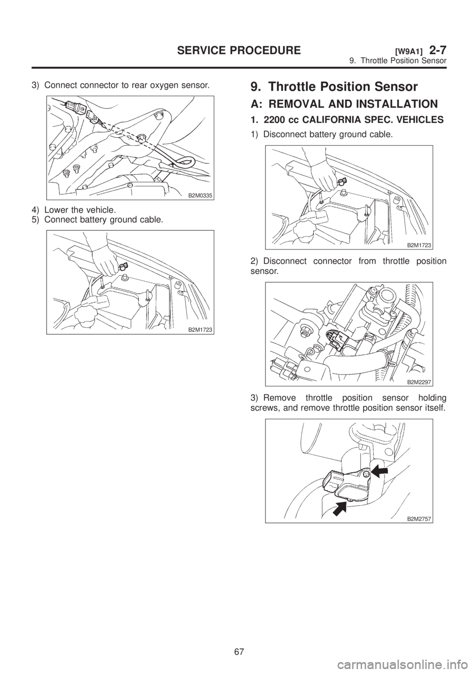
9. Throttle Position Sensor
A: REMOVAL AND INSTALLATION
1. 2200 cc CALIFORNIA SPEC. VEHICLES
1) Disconnect battery ground cable.
B2M1723
2) Disconnect connector from throttle position
sensor.
B2M2297
3) Remove throttle position sensor holding
screws, and remove throttle position sensor itself.
B2M2757
67
[W9A1]2-7SERVICE PROCEDURE
9. Throttle Position Sensor
Page 330 of 1456
3) Connect connector to rear oxygen sensor.
B2M0335
4) Lower the vehicle.
5) Connect battery ground cable.
B2M1723
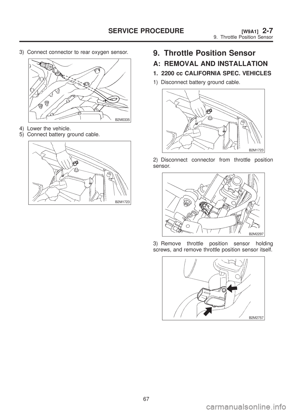
9. Throttle Position Sensor
A: REMOVAL AND INSTALLATION
1. 2200 cc CALIFORNIA SPEC. VEHICLES
1) Disconnect battery ground cable.
B2M1723
2) Disconnect connector from throttle position
sensor.
B2M2297
3) Remove throttle position sensor holding
screws, and remove throttle position sensor itself.
B2M2757
67
[W9A1]2-7SERVICE PROCEDURE
9. Throttle Position Sensor
Trending: spark plugs replace, brakes, index, fold seats, torque specifications, specifications, vacuum
![SUBARU LEGACY 1999 Service Repair Manual 7. Front Oxygen (A/F) Sensor
A: REMOVAL
1) Disconnect battery ground cable.
B2M1723
2) Disconnect air intake duct (B). (2200 cc Califor-
nia spec. vehicles) <Ref. to 2-7 [W1A1].>
B2M2330A
3) Remove ai SUBARU LEGACY 1999 Service Repair Manual 7. Front Oxygen (A/F) Sensor
A: REMOVAL
1) Disconnect battery ground cable.
B2M1723
2) Disconnect air intake duct (B). (2200 cc Califor-
nia spec. vehicles) <Ref. to 2-7 [W1A1].>
B2M2330A
3) Remove ai](/img/17/57435/w960_57435-324.png)
