SUBARU LEGACY 1999 Service Repair Manual
LEGACY 1999
SUBARU
SUBARU
https://www.carmanualsonline.info/img/17/57435/w960_57435-0.png
SUBARU LEGACY 1999 Service Repair Manual
Trending: checking oil, clock, oil level, headrest, boot, jump cable, window
Page 971 of 1456
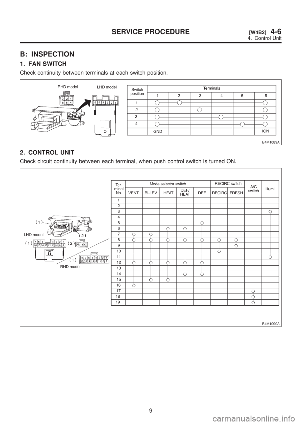
B: INSPECTION
1. FAN SWITCH
Check continuity between terminals at each switch position.
B4M1089A
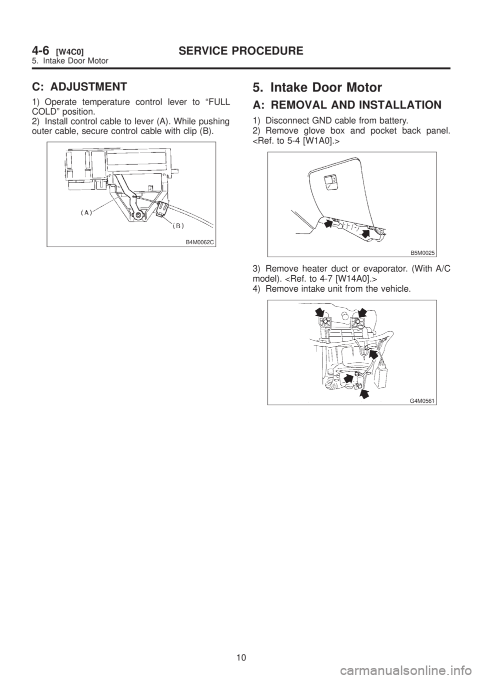
2. CONTROL UNIT
Check circuit continuity between each terminal, when push control switch is turned ON.
B4M1090A
9
[W4B2]4-6SERVICE PROCEDURE
4. Control Unit
Page 972 of 1456
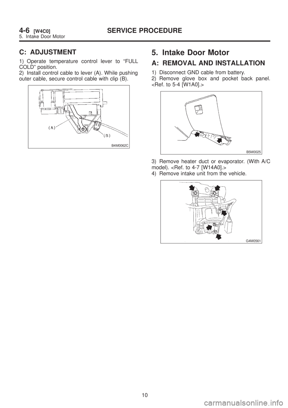
C: ADJUSTMENT
1) Operate temperature control lever to ªFULL
COLDº position.
2) Install control cable to lever (A). While pushing
outer cable, secure control cable with clip (B).
B4M0062C
5. Intake Door Motor
A: REMOVAL AND INSTALLATION
1) Disconnect GND cable from battery.
2) Remove glove box and pocket back panel.
B5M0025
3) Remove heater duct or evaporator. (With A/C
model).
4) Remove intake unit from the vehicle.
G4M0561
10
4-6[W4C0]SERVICE PROCEDURE
5. Intake Door Motor
Page 973 of 1456
C: ADJUSTMENT
1) Operate temperature control lever to ªFULL
COLDº position.
2) Install control cable to lever (A). While pushing
outer cable, secure control cable with clip (B).
B4M0062C
5. Intake Door Motor
A: REMOVAL AND INSTALLATION
1) Disconnect GND cable from battery.
2) Remove glove box and pocket back panel.
B5M0025
3) Remove heater duct or evaporator. (With A/C
model).
4) Remove intake unit from the vehicle.
G4M0561
10
4-6[W4C0]SERVICE PROCEDURE
5. Intake Door Motor
Page 974 of 1456
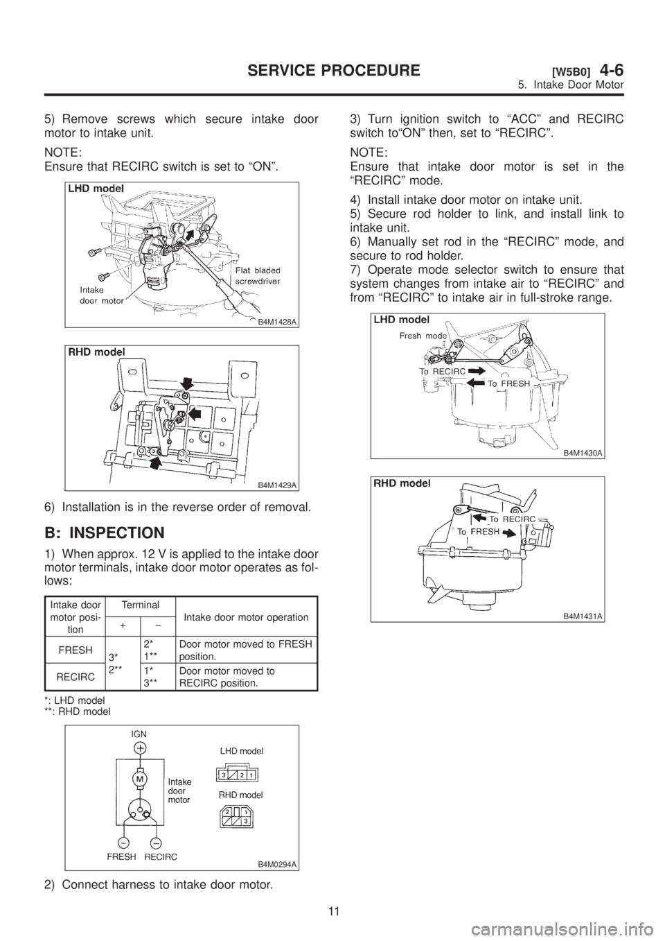
5) Remove screws which secure intake door
motor to intake unit.
NOTE:
Ensure that RECIRC switch is set to ªONº.
B4M1428A
B4M1429A
6) Installation is in the reverse order of removal.
B: INSPECTION
1) When approx. 12 V is applied to the intake door
motor terminals, intake door motor operates as fol-
lows:
Intake door
motor posi-
tionTerminal
Intake door motor operation
+þ
FRESH
3*
2**2*
1**Door motor moved to FRESH
position.
RECIRC1*
3**Door motor moved to
RECIRC position.
*: LHD model
**: RHD model
B4M0294A
2) Connect harness to intake door motor.3) Turn ignition switch to ªACCº and RECIRC
switch toªONº then, set to ªRECIRCº.
NOTE:
Ensure that intake door motor is set in the
ªRECIRCº mode.
4) Install intake door motor on intake unit.
5) Secure rod holder to link, and install link to
intake unit.
6) Manually set rod in the ªRECIRCº mode, and
secure to rod holder.
7) Operate mode selector switch to ensure that
system changes from intake air to ªRECIRCº and
from ªRECIRCº to intake air in full-stroke range.
B4M1430A
B4M1431A
11
[W5B0]4-6SERVICE PROCEDURE
5. Intake Door Motor
Page 975 of 1456
6. Mode Door Motor
A: REMOVAL AND INSTALLATION
1) Remove instrument panel.
2) Remove mode door motor.
B4M0063
3) Installation is in the reverse order of removal.
B: INSPECTION
1) When approx. 12 V is applied to the mode door motor terminals, mode door motor operates as follows:
B4M1092A
2) Check mode door motor position switch.
When the mode door motor is moved to each mode position by using the mode selector switch, check if
continuity exists between each terminal as follows:
Mode selector switch positions Terminal No.
VENT 8 or 7
9 (GND) BI-LEV 6 or 7
HEAT 5 or 6
DEF/HEAT 4 or 5
DEF 3or4
12
4-6[W6A0]SERVICE PROCEDURE
6. Mode Door Motor
Page 976 of 1456
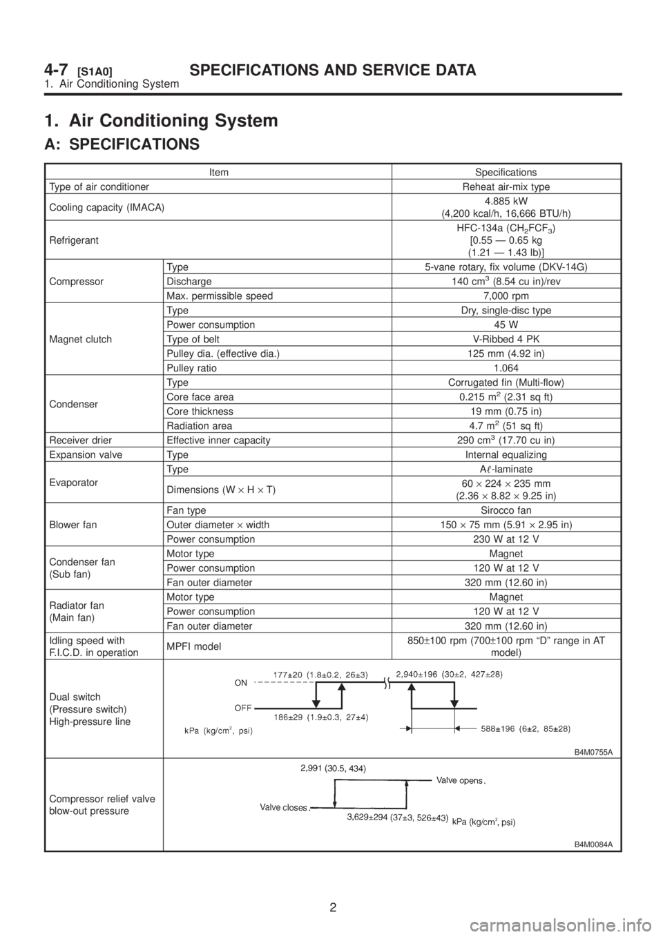
1. Air Conditioning System
A: SPECIFICATIONS
Item Specifications
Type of air conditioner Reheat air-mix type
Cooling capacity (IMACA)4.885 kW
(4,200 kcal/h, 16,666 BTU/h)
RefrigerantHFC-134a (CH
2FCF3)
[0.55 Ð 0.65 kg
(1.21 Ð 1.43 lb)]
CompressorType 5-vane rotary, fix volume (DKV-14G)
Discharge 140 cm
3(8.54 cu in)/rev
Max. permissible speed 7,000 rpm
Magnet clutchType Dry, single-disc type
Power consumption 45 W
Type of belt V-Ribbed 4 PK
Pulley dia. (effective dia.) 125 mm (4.92 in)
Pulley ratio 1.064
CondenserType Corrugated fin (Multi-flow)
Core face area 0.215 m
2(2.31 sq ft)
Core thickness 19 mm (0.75 in)
Radiation area 4.7 m
2(51 sq ft)
Receiver drier Effective inner capacity 290 cm3(17.70 cu in)
Expansion valve Type Internal equalizing
EvaporatorType A-laminate
Dimensions (W´H´T)60´224´235 mm
(2.36´8.82´9.25 in)
Blower fanFan type Sirocco fan
Outer diameter´width 150´75 mm (5.91´2.95 in)
Power consumption 230 W at 12 V
Condenser fan
(Sub fan)Motor type Magnet
Power consumption 120 W at 12 V
Fan outer diameter 320 mm (12.60 in)
Radiator fan
(Main fan)Motor type Magnet
Power consumption 120 W at 12 V
Fan outer diameter 320 mm (12.60 in)
Idling speed with
F.I.C.D. in operationMPFI model850±100 rpm (700±100 rpm ªDº range in AT
model)
Dual switch
(Pressure switch)
High-pressure line
B4M0755A
Compressor relief valve
blow-out pressure
B4M0084A
2
4-7[S1A0]SPECIFICATIONS AND SERVICE DATA
1. Air Conditioning System
Page 977 of 1456
Item Specifications
Thermo control amplifier
working temperature
(Evaporator outlet air)
B4M0756B
3
[S1A0]4-7SPECIFICATIONS AND SERVICE DATA
1. Air Conditioning System
Page 978 of 1456
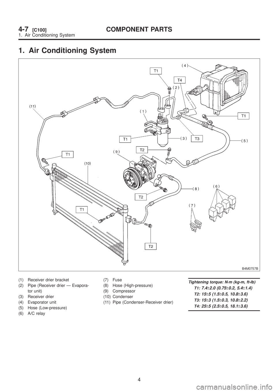
1. Air Conditioning System
B4M0757B
(1) Receiver drier bracket
(2) Pipe (Receiver drier Ð Evapora-
tor unit)
(3) Receiver drier
(4) Evaporator unit
(5) Hose (Low-pressure)
(6) A/C relay(7) Fuse
(8) Hose (High-pressure)
(9) Compressor
(10) Condenser
(11) Pipe (Condenser-Receiver drier)Tightening torque: N´m (kg-m, ft-lb)
T1:
7.4±2.0 (0.75±0.2, 5.4±1.4)
T2:15±5 (1.5±0.5, 10.8±3.6)
T3:15±3 (1.5±0.3, 10.8±2.2)
T4:25±5 (2.5±0.5, 18.1±3.6)
4
4-7[C100]COMPONENT PARTS
1. Air Conditioning System
Page 979 of 1456
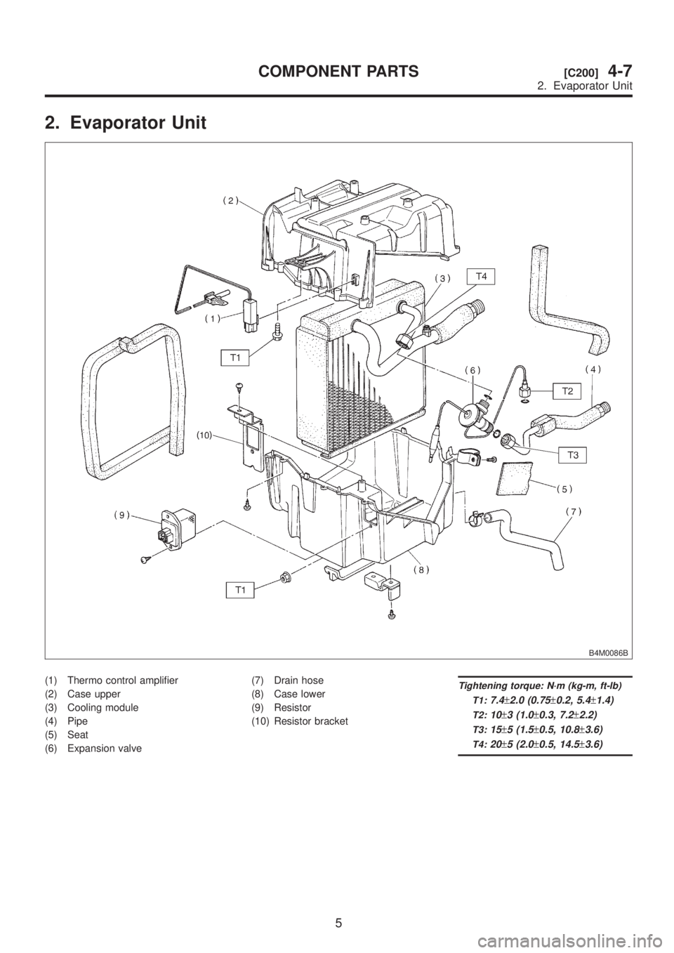
2. Evaporator Unit
B4M0086B
(1) Thermo control amplifier
(2) Case upper
(3) Cooling module
(4) Pipe
(5) Seat
(6) Expansion valve(7) Drain hose
(8) Case lower
(9) Resistor
(10) Resistor bracketTightening torque: N´m (kg-m, ft-lb)
T1:
7.4±2.0 (0.75±0.2, 5.4±1.4)
T2:10±3 (1.0±0.3, 7.2±2.2)
T3:15±5 (1.5±0.5, 10.8±3.6)
T4:20±5 (2.0±0.5, 14.5±3.6)
5
[C200]4-7COMPONENT PARTS
2. Evaporator Unit
Page 980 of 1456
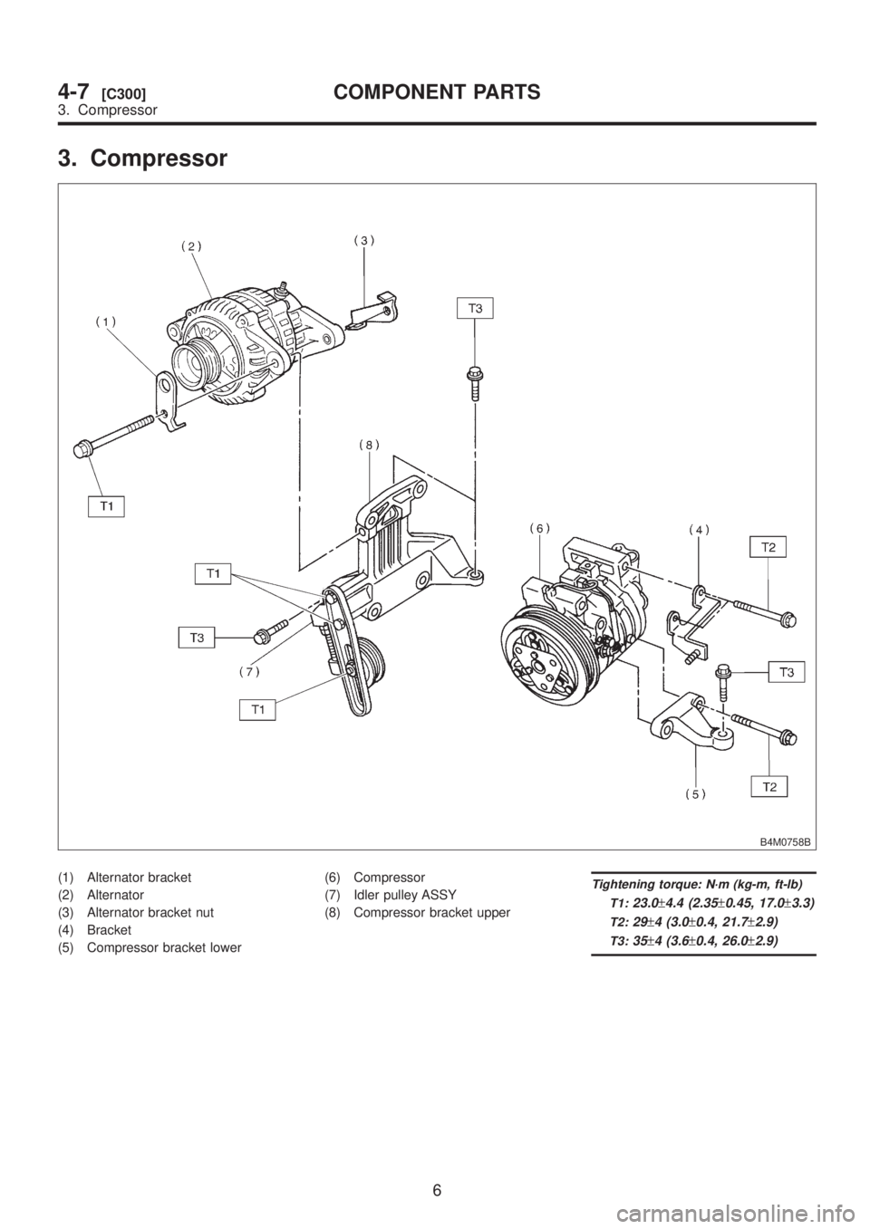
3. Compressor
B4M0758B
(1) Alternator bracket
(2) Alternator
(3) Alternator bracket nut
(4) Bracket
(5) Compressor bracket lower(6) Compressor
(7) Idler pulley ASSY
(8) Compressor bracket upperTightening torque: N´m (kg-m, ft-lb)
T1:
23.0±4.4 (2.35±0.45, 17.0±3.3)
T2:29±4 (3.0±0.4, 21.7±2.9)
T3:35±4 (3.6±0.4, 26.0±2.9)
6
4-7[C300]COMPONENT PARTS
3. Compressor
Trending: fuel tank capacity, jump start, fuel cap release, Wheel bearing, steering, fuse chart, O2 sensor

![SUBARU LEGACY 1999 Service Repair Manual 6. Mode Door Motor
A: REMOVAL AND INSTALLATION
1) Remove instrument panel. <Ref. to 5-4 [W1A0].>
2) Remove mode door motor.
B4M0063
3) Installation is in the reverse order of removal.
B: INSPECTION
1) SUBARU LEGACY 1999 Service Repair Manual 6. Mode Door Motor
A: REMOVAL AND INSTALLATION
1) Remove instrument panel. <Ref. to 5-4 [W1A0].>
2) Remove mode door motor.
B4M0063
3) Installation is in the reverse order of removal.
B: INSPECTION
1)](/img/17/57435/w960_57435-974.png)

![SUBARU LEGACY 1999 Service Repair Manual Item Specifications
Thermo control amplifier
working temperature
(Evaporator outlet air)
B4M0756B
3
[S1A0]4-7SPECIFICATIONS AND SERVICE DATA
1. Air Conditioning System SUBARU LEGACY 1999 Service Repair Manual Item Specifications
Thermo control amplifier
working temperature
(Evaporator outlet air)
B4M0756B
3
[S1A0]4-7SPECIFICATIONS AND SERVICE DATA
1. Air Conditioning System](/img/17/57435/w960_57435-976.png)
