SUBARU LEGACY 1999 Service Repair Manual
LEGACY 1999
SUBARU
SUBARU
https://www.carmanualsonline.info/img/17/57435/w960_57435-0.png
SUBARU LEGACY 1999 Service Repair Manual
Trending: coolant temperature, relay, fog light, replacement, rear view mirror, rear suspension, traction control
Page 1011 of 1456
![SUBARU LEGACY 1999 Service Repair Manual 16. Flexible Hose
A: REMOVAL AND INSTALLATION
1) Disconnect battery negative terminal.
2) Discharge refrigerant using refrigerant recovery
system. <Ref. to 4-7 [W6A0].>
3) Remove low-pressure hose:
CA SUBARU LEGACY 1999 Service Repair Manual 16. Flexible Hose
A: REMOVAL AND INSTALLATION
1) Disconnect battery negative terminal.
2) Discharge refrigerant using refrigerant recovery
system. <Ref. to 4-7 [W6A0].>
3) Remove low-pressure hose:
CA](/img/17/57435/w960_57435-1010.png)
16. Flexible Hose
A: REMOVAL AND INSTALLATION
1) Disconnect battery negative terminal.
2) Discharge refrigerant using refrigerant recovery
system.
3) Remove low-pressure hose:
CAUTION:
With the following cautions, replace flexible
hoses with new ones if they are damaged or
swollen.
IThe flexible hoses should be free from twists
and tension after they have been connected.
IThe flexible hoses must not be bent or
twisted forcibly.
(1) Remove hose attaching bolts.
CAUTION:
Plug the opening to prevent foreign matter
from getting in.
(2) Disconnect the connector at evaporator
unit.
B4M0103
4) Remove high-pressure hose:
CAUTION:
With the following cautions, replace flexible
hoses with new ones if they are damaged or
swollen.
IThe flexible hoses should be free from twists
and tension after they have been connected.
IThe flexible hoses must not be bent or
twisted forcibly.
(1) Disconnect hose attaching bolt (compressor
side).
(2) Disconnect hose attaching bolt (condenser
side).
CAUTION:
Plug the opening to prevent foreign matter
from getting in.
B4M0764
5) Installation is in the reverse order of removal.
6) Charge refrigerant.
31
[W16A0]4-7SERVICE PROCEDURE
16. Flexible Hose
Page 1012 of 1456
17. Relay and Fuse
A: LOCATION
Relays used with A/C system are located as shown
in figure.
IA/C relay
IMain fan (radiator fan) relay
ISub fan (condenser fan) relay
ISub fan (condenser fan) water temperature
relay
IFuses (10 A and 20 A)
G4M0649
B: INSPECTION
1) Check conduction with a circuit tester (ohm
range) according to the following table in figure.
G4M0651
2) Replace relays which do not meet specifica-
tions.
B4M0105A
32
4-7[W17A0]SERVICE PROCEDURE
17. Relay and Fuse
Page 1013 of 1456
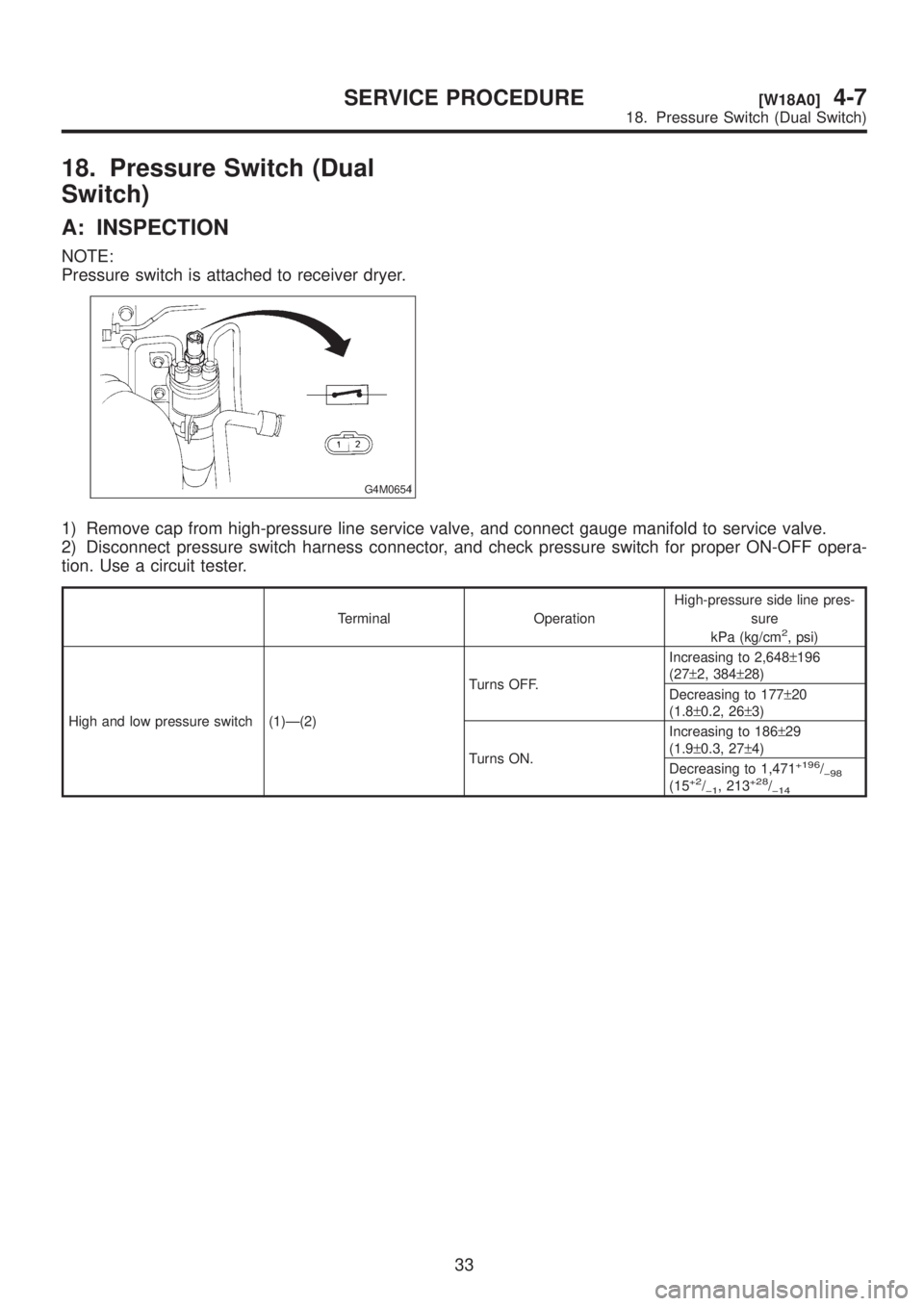
18. Pressure Switch (Dual
Switch)
A: INSPECTION
NOTE:
Pressure switch is attached to receiver dryer.
G4M0654
1) Remove cap from high-pressure line service valve, and connect gauge manifold to service valve.
2) Disconnect pressure switch harness connector, and check pressure switch for proper ON-OFF opera-
tion. Use a circuit tester.
Terminal OperationHigh-pressure side line pres-
sure
kPa (kg/cm2, psi)
High and low pressure switch (1)Ð(2)Turns OFF.Increasing to 2,648±196
(27±2, 384±28)
Decreasing to 177±20
(1.8±0.2, 26±3)
Turns ON.Increasing to 186±29
(1.9±0.3, 27±4)
Decreasing to 1,471
+196/þ98(15+2/þ1, 213+28/þ14
33
[W18A0]4-7SERVICE PROCEDURE
18. Pressure Switch (Dual Switch)
Page 1014 of 1456
1. Air Conditioning System
Diagnosis
B4M1099A
34
4-7[K100]DIAGNOSTICS
1. Air Conditioning System Diagnosis
Page 1015 of 1456
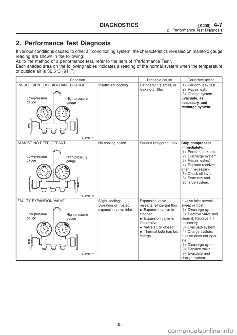
2. Performance Test Diagnosis
If various conditions caused to other air conditioning system, the characteristics revealed on manifold gauge
reading are shown in the following:
As to the method of a performance test, refer to the item of ªPerformance Testº.
Each shaded area on the following tables indicates a reading of the normal system when the temperature
of outside air is 32.5ÉC (91ÉF).
Condition Probable cause Corrective action
INSUFFICIENT REFRIGERANT CHARGE
G4M0673
Insufficient cooling Refrigerant is small, or
leaking a little.(1) Perform leak test.
(2) Repair leak.
(3) Charge system.
Evacuate, as
necessary, and
recharge system.
ALMOST NO REFRIGERANT
G4M0674
No cooling action Serious refrigerant leak.Stop compressor
immediately.
(1) Perform leak test.
(2) Discharge system.
(3) Repair leak(s).
(4) Replace receiver
drier if necessary.
(5) Check oil level.
(6) Evacuate and
recharge system.
FAULTY EXPANSION VALVE
G4M0675
Slight cooling;
Sweating or frosted
expansion valve inlet.Expansion valve
restricts refrigerant flow.
IExpansion valve is
clogged.
IExpansion valve is
inoperative.
IValve stuck closed.
IThermal bulb has lost
charge.If valve inlet reveals
sweat or frost:
(1) Discharge system
(2) Remove valve and
clean it. Replace it if
necessary.
(3) Evacuate system
(4) Charge system.
If valve does not oper-
ate:
(1) Discharge system.
(2) Replace valve.
(3) Evacuate and
charge system.
35
[K200]4-7DIAGNOSTICS
2. Performance Test Diagnosis
Page 1016 of 1456
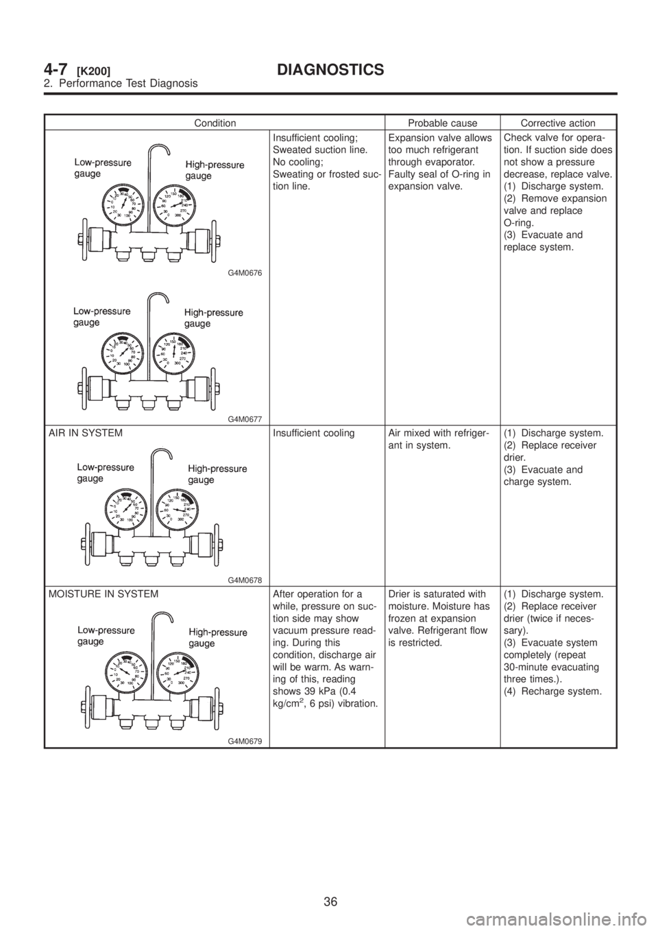
Condition Probable cause Corrective action
G4M0676
G4M0677
Insufficient cooling;
Sweated suction line.
No cooling;
Sweating or frosted suc-
tion line.Expansion valve allows
too much refrigerant
through evaporator.
Faulty seal of O-ring in
expansion valve.Check valve for opera-
tion. If suction side does
not show a pressure
decrease, replace valve.
(1) Discharge system.
(2) Remove expansion
valve and replace
O-ring.
(3) Evacuate and
replace system.
AIR IN SYSTEM
G4M0678
Insufficient cooling Air mixed with refriger-
ant in system.(1) Discharge system.
(2) Replace receiver
drier.
(3) Evacuate and
charge system.
MOISTURE IN SYSTEM
G4M0679
After operation for a
while, pressure on suc-
tion side may show
vacuum pressure read-
ing. During this
condition, discharge air
will be warm. As warn-
ing of this, reading
shows 39 kPa (0.4
kg/cm
2, 6 psi) vibration.Drier is saturated with
moisture. Moisture has
frozen at expansion
valve. Refrigerant flow
is restricted.(1) Discharge system.
(2) Replace receiver
drier (twice if neces-
sary).
(3) Evacuate system
completely (repeat
30-minute evacuating
three times.).
(4) Recharge system.
36
4-7[K200]DIAGNOSTICS
2. Performance Test Diagnosis
Page 1017 of 1456
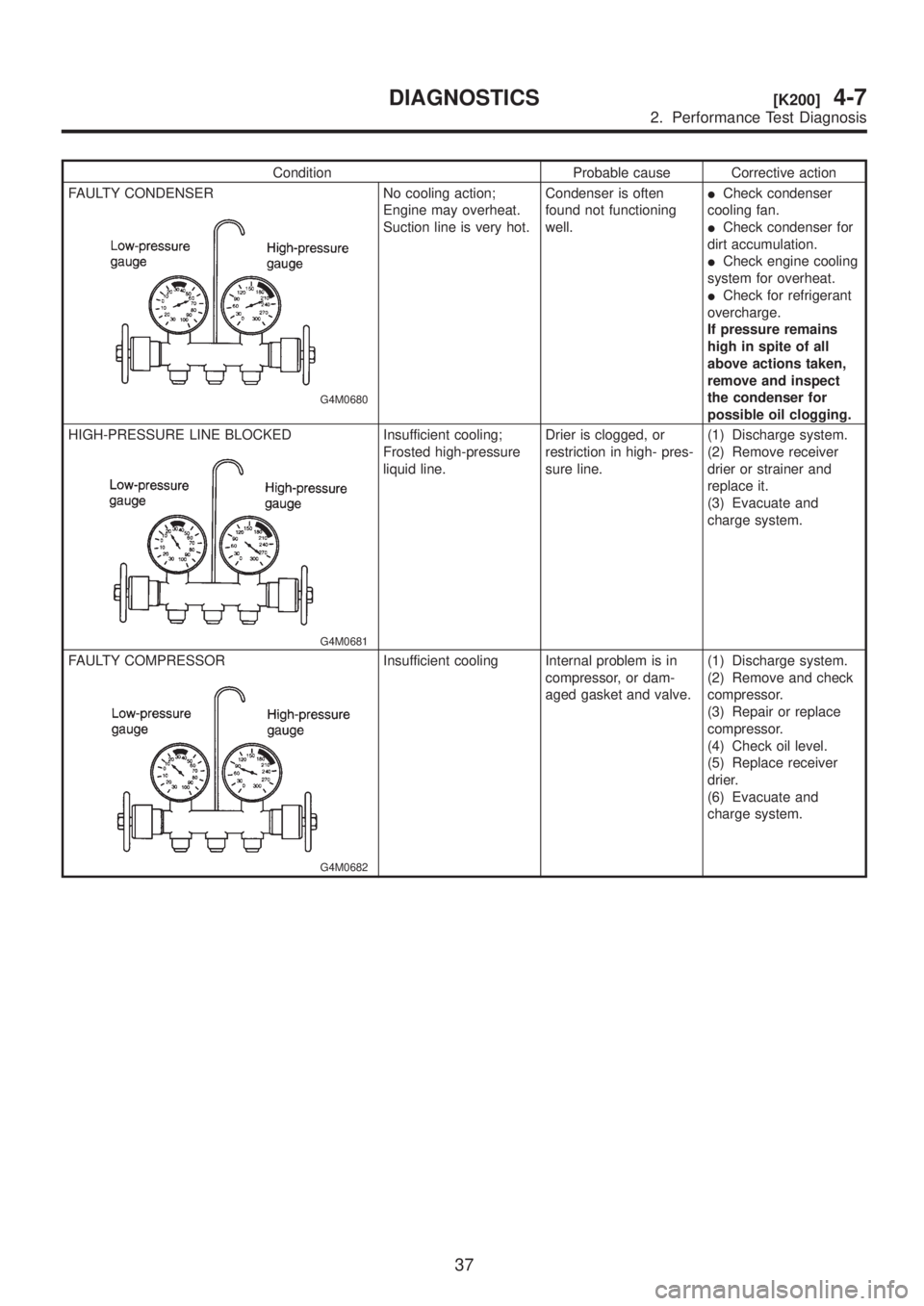
Condition Probable cause Corrective action
FAULTY CONDENSER
G4M0680
No cooling action;
Engine may overheat.
Suction line is very hot.Condenser is often
found not functioning
well.ICheck condenser
cooling fan.
ICheck condenser for
dirt accumulation.
ICheck engine cooling
system for overheat.
ICheck for refrigerant
overcharge.
If pressure remains
high in spite of all
above actions taken,
remove and inspect
the condenser for
possible oil clogging.
HIGH-PRESSURE LINE BLOCKED
G4M0681
Insufficient cooling;
Frosted high-pressure
liquid line.Drier is clogged, or
restriction in high- pres-
sure line.(1) Discharge system.
(2) Remove receiver
drier or strainer and
replace it.
(3) Evacuate and
charge system.
FAULTY COMPRESSOR
G4M0682
Insufficient cooling Internal problem is in
compressor, or dam-
aged gasket and valve.(1) Discharge system.
(2) Remove and check
compressor.
(3) Repair or replace
compressor.
(4) Check oil level.
(5) Replace receiver
drier.
(6) Evacuate and
charge system.
37
[K200]4-7DIAGNOSTICS
2. Performance Test Diagnosis
Page 1018 of 1456
3. Blower Motor Diagnosis
B4M1103A
38
4-7[K300]DIAGNOSTICS
3. Blower Motor Diagnosis
Page 1019 of 1456
4. Compressor Diagnosis
B4M1104A
39
[K400]4-7DIAGNOSTICS
4. Compressor Diagnosis
Page 1020 of 1456
5. Compressor Clutch Diagnosis
B4M1105A
40
4-7[K500]DIAGNOSTICS
5. Compressor Clutch Diagnosis
Trending: warning lights, oil, air bleeding, change wheel, hood open, reset, compression ratio
![SUBARU LEGACY 1999 Service Repair Manual 16. Flexible Hose
A: REMOVAL AND INSTALLATION
1) Disconnect battery negative terminal.
2) Discharge refrigerant using refrigerant recovery
system. <Ref. to 4-7 [W6A0].>
3) Remove low-pressure hose:
CA SUBARU LEGACY 1999 Service Repair Manual 16. Flexible Hose
A: REMOVAL AND INSTALLATION
1) Disconnect battery negative terminal.
2) Discharge refrigerant using refrigerant recovery
system. <Ref. to 4-7 [W6A0].>
3) Remove low-pressure hose:
CA](/img/17/57435/w960_57435-1010.png)
![SUBARU LEGACY 1999 Service Repair Manual 1. Air Conditioning System
Diagnosis
B4M1099A
34
4-7[K100]DIAGNOSTICS
1. Air Conditioning System Diagnosis SUBARU LEGACY 1999 Service Repair Manual 1. Air Conditioning System
Diagnosis
B4M1099A
34
4-7[K100]DIAGNOSTICS
1. Air Conditioning System Diagnosis](/img/17/57435/w960_57435-1013.png)


![SUBARU LEGACY 1999 Service Repair Manual 3. Blower Motor Diagnosis
B4M1103A
38
4-7[K300]DIAGNOSTICS
3. Blower Motor Diagnosis SUBARU LEGACY 1999 Service Repair Manual 3. Blower Motor Diagnosis
B4M1103A
38
4-7[K300]DIAGNOSTICS
3. Blower Motor Diagnosis](/img/17/57435/w960_57435-1017.png)
![SUBARU LEGACY 1999 Service Repair Manual 4. Compressor Diagnosis
B4M1104A
39
[K400]4-7DIAGNOSTICS
4. Compressor Diagnosis SUBARU LEGACY 1999 Service Repair Manual 4. Compressor Diagnosis
B4M1104A
39
[K400]4-7DIAGNOSTICS
4. Compressor Diagnosis](/img/17/57435/w960_57435-1018.png)
![SUBARU LEGACY 1999 Service Repair Manual 5. Compressor Clutch Diagnosis
B4M1105A
40
4-7[K500]DIAGNOSTICS
5. Compressor Clutch Diagnosis SUBARU LEGACY 1999 Service Repair Manual 5. Compressor Clutch Diagnosis
B4M1105A
40
4-7[K500]DIAGNOSTICS
5. Compressor Clutch Diagnosis](/img/17/57435/w960_57435-1019.png)