diff SUBARU TRIBECA 2009 1.G Service Owners Manual
[x] Cancel search | Manufacturer: SUBARU, Model Year: 2009, Model line: TRIBECA, Model: SUBARU TRIBECA 2009 1.GPages: 2453, PDF Size: 46.32 MB
Page 1718 of 2453
GD(H6DO)-106
Diagnostic Trouble Code (DTC) Detecting Criteria
GENERAL DESCRIPTION
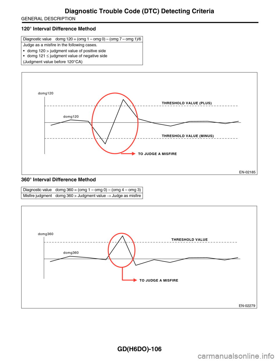
120° Interval Difference Method
360° Interval Difference Method
Diagnostic value domg 120 = (omg 1 – omg 0) – (omg 7 – omg 1)/6
Judge as a misfire in the following cases.
•domg 120 > judgment value of positive side
•domg 121 ≤ judgment value of negative side
(Judgment value before 120°CA)
Diagnostic value domg 360 = (omg 1 – omg 0) – (omg 4 – omg 3)
Misfire judgment domg 360 > Judgment value → Judge as misfire
EN-02185
TO JUDGE A MISFIRE
THRESHOLD VALUE (PLUS)
THRESHOLD VALUE (MINUS)
domg120
domg120
EN-02279
TO JUDGE A MISFIRE
THRESHOLD VALUE
domg360
domg360
Page 1719 of 2453
GD(H6DO)-107
Diagnostic Trouble Code (DTC) Detecting Criteria
GENERAL DESCRIPTION
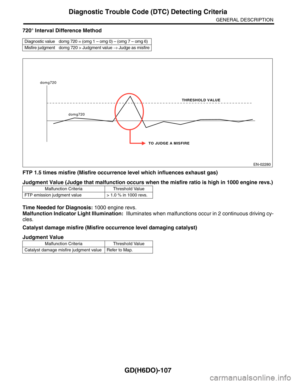
720° Interval Difference Method
FTP 1.5 times misfire (Misfire occurrence level which influences exhaust gas)
Time Needed for Diagnosis: 1000 engine revs.
Malfunction Indicator Light Illumination: Illuminates when malfunctions occur in 2 continuous driving cy-
cles.
Catalyst damage misfire (Misfire occurrence level damaging catalyst)
Diagnostic value domg 720 = (omg 1 – omg 0) – (omg 7 – omg 6)
Misfire judgment domg 720 > Judgment value → Judge as misfire
Judgment Value (Judge that malfunction occurs when the misfire ratio is high in 1000 engine revs.)
Malfunction Criteria Threshold Value
FTP emission judgment value > 1.0 % in 1000 revs.
Judgment Value
Malfunction Criteria Threshold Value
Catalyst damage misfire judgment value Refer to Map.
EN-02280
TO JUDGE A MISFIRE
THRESHOLD VALUE
domg720
domg720
Page 1734 of 2453
GD(H6DO)-122
Diagnostic Trouble Code (DTC) Detecting Criteria
GENERAL DESCRIPTION
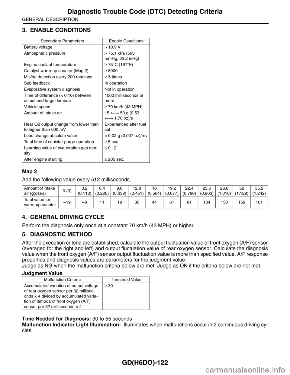
3. ENABLE CONDITIONS
Map 2
Add the following value every 512 milliseconds.
4. GENERAL DRIVING CYCLE
Perform the diagnosis only once at a constant 70 km/h (43 MPH) or higher.
5. DIAGNOSTIC METHOD
After the execution criteria are established, calculate the output fluctuation value of front oxygen (A/F) sensor
(averaged for the right and left) and output fluctuation value of rear oxygen sensor. Calculate the diagnosis
value when the front oxygen (A/F) sensor output fluctuation value is more than specified value. A/F response
properties and diagnosis values are parameters for the judgment value.
Judge as NG when the malfunction criteria below are met. Judge as OK if the criteria below are not met.
Time Needed for Diagnosis: 30 to 55 seconds
Malfunction Indicator Light Illumination: Illuminates when malfunctions occur in 2 continuous driving cy-
cles.
Secondary Parameters Enable Conditions
Battery voltage > 10.9 V
Atmospheric pressure > 75.1 kPa (563
mmHg, 22.2 inHg)
Engine coolant temperature≥ 75°C (167°F)
Catalyst warm-up counter (Map 2)≥ 8000
Misfire detection every 200 rotations < 5 times
Sub feedback In operation
Evaporative system diagnosis Not in operation
Time of difference (< 0.10) between
actual and target lambda
1000 milliseconds or
more
Ve h i c l e s p e e d≥ 70 km/h (43 MPH)
Amount of intake air 15 ←→ 50 g (0.53
←→ 1.76 oz)/s
Rear O2 output change from lower than
to higher than 600 mV
Experienced after fuel
cut
Load change absolute value < 0.02 g (0.007 oz)/rev
To t a l t i m e o f c a n i s t e r p u r g e o p e r a t i o n≥ 5 sec.
Learning value of evaporation gas den-
sity
≤ 0.12
After engine starting≥ 205 sec.
Amount of intake
air (g(oz)/s)0 (0)3.2
(0.113)
6.4
(0.226)
9.6
(0.339)
12.8
(0.451)
16
(0.564)
19.2
(0.677)
22.4
(0.790)
25.6
(0.903)
28.8
(1.016)
32
(1.129)
35.2
(1.242)
To t a l v a l u e f o r
warm-up counter–19 –8 11 19 30 44 61 81 104 130 159 161
Judgment Value
Malfunction Criteria Threshold Value
Accumulated variation of output voltage
of rear oxygen sensor per 32 millisec-
onds × 4 divided by accumulated varia-
tion of lambda of front oxygen (A/F)
sensor per 32 milliseconds × 4
≥ 30
Page 1748 of 2453
GD(H6DO)-136
Diagnostic Trouble Code (DTC) Detecting Criteria
GENERAL DESCRIPTION
CD:DTC P0447 EVAPORATIVE EMISSION CONTROL SYSTEM VENT CONTROL
CIRCUIT OPEN
1. OUTLINE OF DIAGNOSIS
Detect open or short circuit of the drain valve.
Judge as NG when the ECM output level differs from the actual terminal level.
2. COMPONENT DESCRIPTION
The drain valve adjusts the pressure in the canister by introducing/extracting air when pressure differences
occur in the canister with the atmospheric pressure.
3. ENABLE CONDITIONS
4. GENERAL DRIVING CYCLE
Always perform the diagnosis continuously.
5. DIAGNOSTIC METHOD
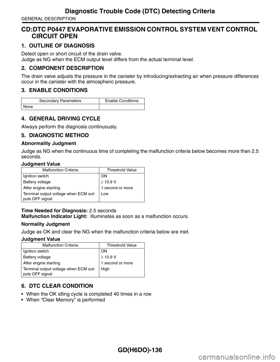
Abnormality Judgment
Judge as NG when the continuous time of completing the malfunction criteria below becomes more than 2.5
seconds.
Time Needed for Diagnosis: 2.5 seconds
Malfunction Indicator Light: Illuminates as soon as a malfunction occurs.
Normality Judgment
Judge as OK and clear the NG when the malfunction criteria below are met.
6. DTC CLEAR CONDITION
•When the OK idling cycle is completed 40 times in a row
•When “Clear Memory” is performed
Secondary Parameters Enable Conditions
None
Judgment Value
Malfunction Criteria Threshold Value
Ignition switch ON
Battery voltage≥ 10.9 V
After engine starting 1 second or more
Te r m i n a l o u t p u t v o l t a g e w h e n E C M o u t -
puts OFF signal
Low
Judgment Value
Malfunction Criteria Threshold Value
Ignition switch ON
Battery voltage≥ 10.9 V
After engine starting 1 second or more
Te r m i n a l o u t p u t v o l t a g e w h e n E C M o u t -
puts OFF signal
High
Page 1750 of 2453
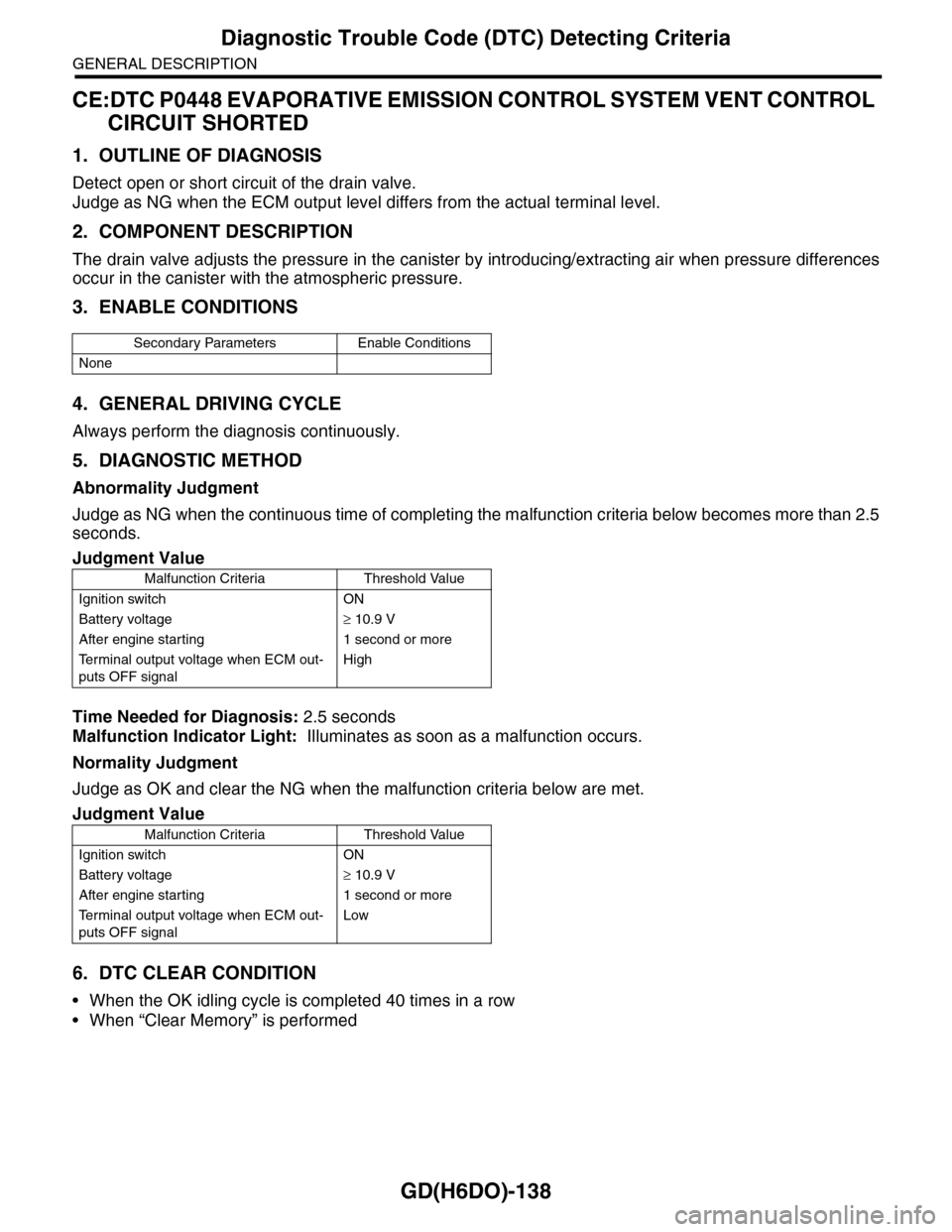
GD(H6DO)-138
Diagnostic Trouble Code (DTC) Detecting Criteria
GENERAL DESCRIPTION
CE:DTC P0448 EVAPORATIVE EMISSION CONTROL SYSTEM VENT CONTROL
CIRCUIT SHORTED
1. OUTLINE OF DIAGNOSIS
Detect open or short circuit of the drain valve.
Judge as NG when the ECM output level differs from the actual terminal level.
2. COMPONENT DESCRIPTION
The drain valve adjusts the pressure in the canister by introducing/extracting air when pressure differences
occur in the canister with the atmospheric pressure.
3. ENABLE CONDITIONS
4. GENERAL DRIVING CYCLE
Always perform the diagnosis continuously.
5. DIAGNOSTIC METHOD
Abnormality Judgment
Judge as NG when the continuous time of completing the malfunction criteria below becomes more than 2.5
seconds.
Time Needed for Diagnosis: 2.5 seconds
Malfunction Indicator Light: Illuminates as soon as a malfunction occurs.
Normality Judgment
Judge as OK and clear the NG when the malfunction criteria below are met.
6. DTC CLEAR CONDITION
•When the OK idling cycle is completed 40 times in a row
•When “Clear Memory” is performed
Secondary Parameters Enable Conditions
None
Judgment Value
Malfunction Criteria Threshold Value
Ignition switch ON
Battery voltage≥ 10.9 V
After engine starting 1 second or more
Te r m i n a l o u t p u t v o l t a g e w h e n E C M o u t -
puts OFF signal
High
Judgment Value
Malfunction Criteria Threshold Value
Ignition switch ON
Battery voltage≥ 10.9 V
After engine starting 1 second or more
Te r m i n a l o u t p u t v o l t a g e w h e n E C M o u t -
puts OFF signal
Low
Page 1753 of 2453
GD(H6DO)-141
Diagnostic Trouble Code (DTC) Detecting Criteria
GENERAL DESCRIPTION
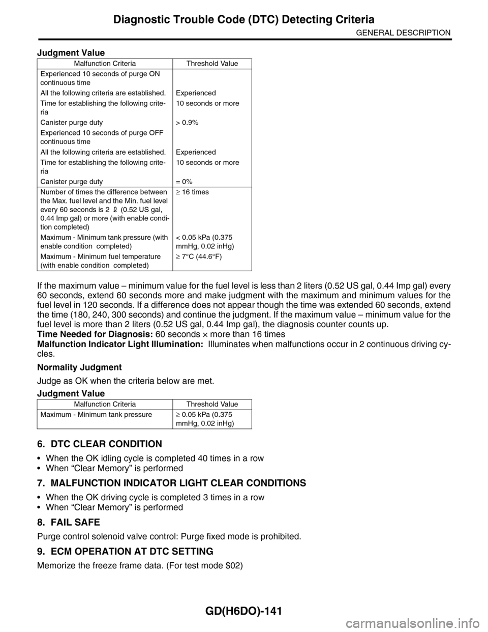
If the maximum value – minimum value for the fuel level is less than 2 liters (0.52 US gal, 0.44 Imp gal) every
60 seconds, extend 60 seconds more and make judgment with the maximum and minimum values for the
fuel level in 120 seconds. If a difference does not appear though the time was extended 60 seconds, extend
the time (180, 240, 300 seconds) and continue the judgment. If the maximum value – minimum value for the
fuel level is more than 2 liters (0.52 US gal, 0.44 Imp gal), the diagnosis counter counts up.
Time Needed for Diagnosis: 60 seconds × more than 16 times
Malfunction Indicator Light Illumination: Illuminates when malfunctions occur in 2 continuous driving cy-
cles.
Normality Judgment
Judge as OK when the criteria below are met.
6. DTC CLEAR CONDITION
•When the OK idling cycle is completed 40 times in a row
•When “Clear Memory” is performed
7. MALFUNCTION INDICATOR LIGHT CLEAR CONDITIONS
•When the OK driving cycle is completed 3 times in a row
•When “Clear Memory” is performed
8. FAIL SAFE
Purge control solenoid valve control: Purge fixed mode is prohibited.
9. ECM OPERATION AT DTC SETTING
Memorize the freeze frame data. (For test mode $02)
Judgment Value
Malfunction Criteria Threshold Value
Experienced 10 seconds of purge ON
continuous time
All the following criteria are established. Experienced
Time for establishing the following crite-
ria
10 seconds or more
Canister purge duty > 0.9%
Experienced 10 seconds of purge OFF
continuous time
All the following criteria are established. Experienced
Time for establishing the following crite-
ria
10 seconds or more
Canister purge duty = 0%
Number of times the difference between
the Max. fuel level and the Min. fuel level
ever y 60 seconds is 2 2 (0.52 US gal,
0.44 Imp gal) or more (with enable condi-
tion completed)
≥ 16 times
Maximum - Minimum tank pressure (with
enable condition completed)
< 0.05 kPa (0.375
mmHg, 0.02 inHg)
Maximum - Minimum fuel temperature
(with enable condition completed)
≥ 7°C (44.6°F)
Judgment Value
Malfunction Criteria Threshold Value
Maximum - Minimum tank pressure≥ 0.05 kPa (0.375
mmHg, 0.02 inHg)
Page 1759 of 2453
GD(H6DO)-147
Diagnostic Trouble Code (DTC) Detecting Criteria
GENERAL DESCRIPTION
CK:DTC P0458 EVAPORATIVE EMISSION CONTROL SYSTEM PURGE CON-
TROL VALVE CIRCUIT LOW
1. OUTLINE OF DIAGNOSIS
Detect open or short circuit of the purge control solenoid valve.
Judge as NG when the ECM output level differs from the actual terminal level.
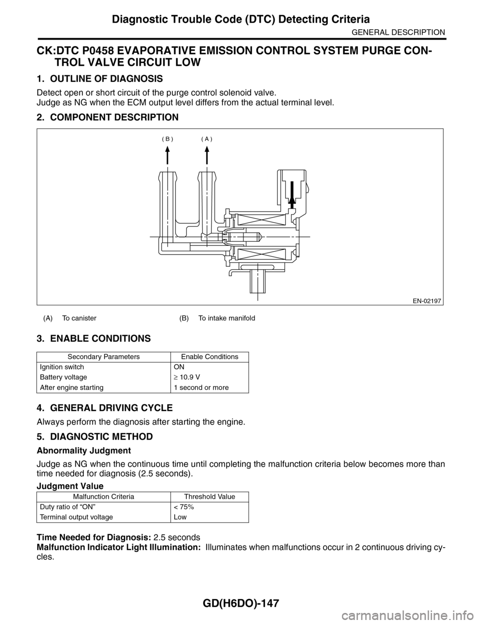
2. COMPONENT DESCRIPTION
3. ENABLE CONDITIONS
4. GENERAL DRIVING CYCLE
Always perform the diagnosis after starting the engine.
5. DIAGNOSTIC METHOD
Abnormality Judgment
Judge as NG when the continuous time until completing the malfunction criteria below becomes more than
time needed for diagnosis (2.5 seconds).
Time Needed for Diagnosis: 2.5 seconds
Malfunction Indicator Light Illumination: Illuminates when malfunctions occur in 2 continuous driving cy-
cles.
(A) To canister (B) To intake manifold
Secondary Parameters Enable Conditions
Ignition switch ON
Battery voltage≥ 10.9 V
After engine starting 1 second or more
Judgment Value
Malfunction Criteria Threshold Value
Duty ratio of “ON” < 75%
Te r m i n a l o u t p u t v o l t a g e L o w
EN-02197
( A )( B )
Page 1761 of 2453
GD(H6DO)-149
Diagnostic Trouble Code (DTC) Detecting Criteria
GENERAL DESCRIPTION
CL:DTC P0459 EVAPORATIVE EMISSION CONTROL SYSTEM PURGE CON-
TROL VALVE CIRCUIT HIGH
1. OUTLINE OF DIAGNOSIS
Detect open or short circuit of the purge control solenoid valve.
Judge as NG when the ECM output level differs from the actual terminal level.
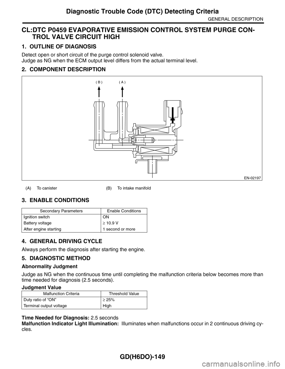
2. COMPONENT DESCRIPTION
3. ENABLE CONDITIONS
4. GENERAL DRIVING CYCLE
Always perform the diagnosis after starting the engine.
5. DIAGNOSTIC METHOD
Abnormality Judgment
Judge as NG when the continuous time until completing the malfunction criteria below becomes more than
time needed for diagnosis (2.5 seconds).
Time Needed for Diagnosis: 2.5 seconds
Malfunction Indicator Light Illumination: Illuminates when malfunctions occur in 2 continuous driving cy-
cles.
(A) To canister (B) To intake manifold
Secondary Parameters Enable Conditions
Ignition switch ON
Battery voltage≥ 10.9 V
After engine starting 1 second or more
Judgment Value
Malfunction Criteria Threshold Value
Duty ratio of “ON”≥ 25%
Te r m i n a l o u t p u t v o l t a g e H i g h
EN-02197
( A )( B )
Page 1770 of 2453
GD(H6DO)-158
Diagnostic Trouble Code (DTC) Detecting Criteria
GENERAL DESCRIPTION
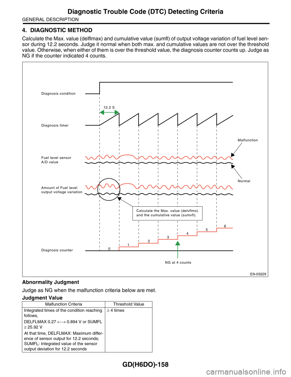
4. DIAGNOSTIC METHOD
Calculate the Max. value (delflmax) and cumulative value (sumfl) of output voltage variation of fuel level sen-
sor during 12.2 seconds. Judge it normal when both max. and cumulative values are not over the threshold
value. Otherwise, when either of them is over the threshold value, the diagnosis counter counts up. Judge as
NG if the counter indicated 4 counts.
Abnormality Judgment
Judge as NG when the malfunction criteria below are met.
Judgment Value
Malfunction Criteria Threshold Value
Integrated times of the condition reaching
follows,
≥ 4 times
DELFLMAX 0.27 ←→ 0.894 V or SUMFL
≥ 25.92 V
At that time, DELFLMAX: Maximum differ-
ence of sensor output for 12.2 seconds;
SUMFL: Integrated value of the sensor
output deviation for 12.2 seconds
Diagnosis condition
Diagnosis timer
12.2 S
Fuel level sensorA/D value
Malfunction
Normal
Amount of Fuel leveloutput voltage variation
Diagnosis counter
NG at 4 counts
Calculate the Max. value (delvflmx) and the cumulative value (sumvfl).
123456
0
EN-03229
Page 1786 of 2453
GD(H6DO)-174
Diagnostic Trouble Code (DTC) Detecting Criteria
GENERAL DESCRIPTION
3. ENABLE CONDITIONS
4. GENERAL DRIVING CYCLE
(1) — (4): Always perform the diagnosis continuously.
(5): Always perform the diagnosis continuously when idling.
(6): Perform the diagnosis when the brake pedal is depressed.
(7): Always perform the diagnosis continuously.
(8): Always perform the diagnosis continuously when the cruise control pedal is not operating.
5. DIAGNOSTIC METHOD
Judge as OK and clear the NG when the malfunction criteria below are met.
Time Needed for Diagnosis:
1. 250 milliseconds
2. 250 milliseconds
3. 200 milliseconds
4. 200 milliseconds
5. 24 milliseconds
6. 250 milliseconds
7. 200 milliseconds
Malfunction Indicator Light: Illuminates as soon as a malfunction occurs.
6. DTC CLEAR CONDITION
•When the OK idling cycle is completed 40 times in a row
•When “Clear Memory” is performed
Secondary Parameters Enable Conditions
(1) Ignition switch ON
(2) Ignition switch ON
(3) None —
(4) None —
(5) Throttle opening angle
(6) Brake SW (only with cruise control) ON
(7) None —
(8) Cruise control OFF
Judgment Value
Malfunction Criteria Threshold Value
(1) Difference of CPU reading value of
the throttle position sensor signal
Within 0.085 V
(2) Difference of CPU read value of the
accelerator position sensor signal
Within 0.047 V
(3) WD pulse from sub CPU WD pulse occur
(4) Communication between CPU Possible to communi-
cate
(5) Throttle position sensor 1 opening
angle — (Throttle position sensor 1
opening angle after passing amplifier) 1/
4
< 3°
(6) Cruise control cancel signal at brake
ON
Cruise control cancel
signal ON
(7) Brake switch 1, 2 signal SW 1 and 2 are
matched