diff SUBARU TRIBECA 2009 1.G Service Workshop Manual
[x] Cancel search | Manufacturer: SUBARU, Model Year: 2009, Model line: TRIBECA, Model: SUBARU TRIBECA 2009 1.GPages: 2453, PDF Size: 46.32 MB
Page 1788 of 2453
GD(H6DO)-176
Diagnostic Trouble Code (DTC) Detecting Criteria
GENERAL DESCRIPTION
DB:DTC P0638 THROTTLE ACTUATOR CONTROL RANGE/PERFORMANCE
(BANK 1)
1. OUTLINE OF DIAGNOSIS
Judge as NG when the target opening angle and actual opening angle is mismatched or the current to motor
is more than specified duty for specified time continuously.
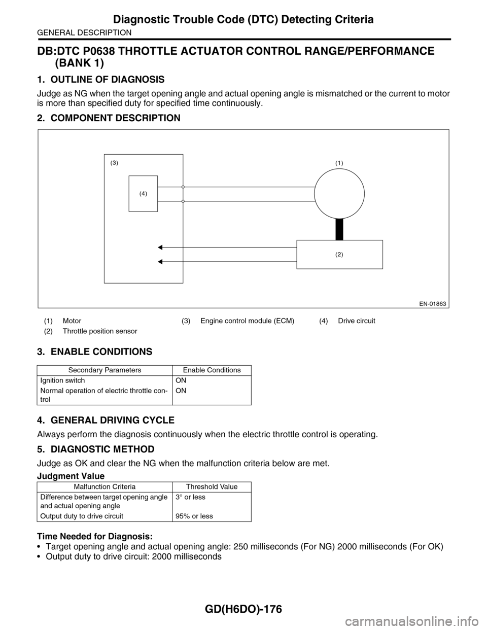
2. COMPONENT DESCRIPTION
3. ENABLE CONDITIONS
4. GENERAL DRIVING CYCLE
Always perform the diagnosis continuously when the electric throttle control is operating.
5. DIAGNOSTIC METHOD
Judge as OK and clear the NG when the malfunction criteria below are met.
Time Needed for Diagnosis:
•Target opening angle and actual opening angle: 250 milliseconds (For NG) 2000 milliseconds (For OK)
•Output duty to drive circuit: 2000 milliseconds
(1) Motor (3) Engine control module (ECM) (4) Drive circuit
(2) Throttle position sensor
Secondary Parameters Enable Conditions
Ignition switch ON
Normal operation of electric throttle con-
trol
ON
Judgment Value
Malfunction Criteria Threshold Value
Difference between target opening angle
and actual opening angle
3° or less
Output duty to drive circuit 95% or less
EN-01863
(3)
(4)
(1)
(2)
Page 1789 of 2453
GD(H6DO)-177
Diagnostic Trouble Code (DTC) Detecting Criteria
GENERAL DESCRIPTION
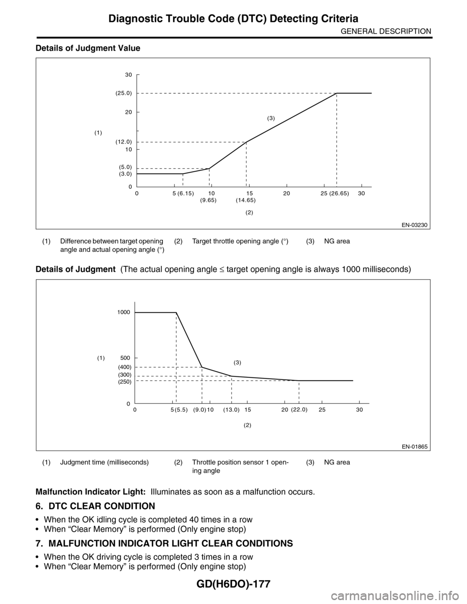
Details of Judgment Value
Details of Judgment (The actual opening angle ≤ target opening angle is always 1000 milliseconds)
Malfunction Indicator Light: Illuminates as soon as a malfunction occurs.
6. DTC CLEAR CONDITION
•When the OK idling cycle is completed 40 times in a row
•When “Clear Memory” is performed (Only engine stop)
7. MALFUNCTION INDICATOR LIGHT CLEAR CONDITIONS
•When the OK driving cycle is completed 3 times in a row
•When “Clear Memory” is performed (Only engine stop)
(1) Difference between target opening
angle and actual opening angle (°)
(2) Target throttle opening angle (°) (3) NG area
(1) Judgment time (milliseconds) (2) Throttle position sensor 1 open-
ing angle
(3) NG area
EN-03230
30
20
10
0
(25.0)
(12.0)
(5.0)(3.0)
05(6.15)10(9.65)(14.65)15 20 25 (26.65) 30
(1)
(3)
(2)
EN-01865
05(5.5)10(9.0)(13.0) 15 20 25 30
(2)
0
1000
(250)
(22.0)
(300)
(400)
500(3)(1)
Page 1791 of 2453
GD(H6DO)-179
Diagnostic Trouble Code (DTC) Detecting Criteria
GENERAL DESCRIPTION
DC:DTC P0691 COOLING FAN 1 CONTROL CIRCUIT LOW
1. OUTLINE OF DIAGNOSIS
Detect the open/short circuit of radiator fan circuit.
Judge as NG when the ECM output level differs from the actual terminal level.
2. ENABLE CONDITIONS
3. GENERAL DRIVING CYCLE
Always perform the diagnosis continuously when idling.
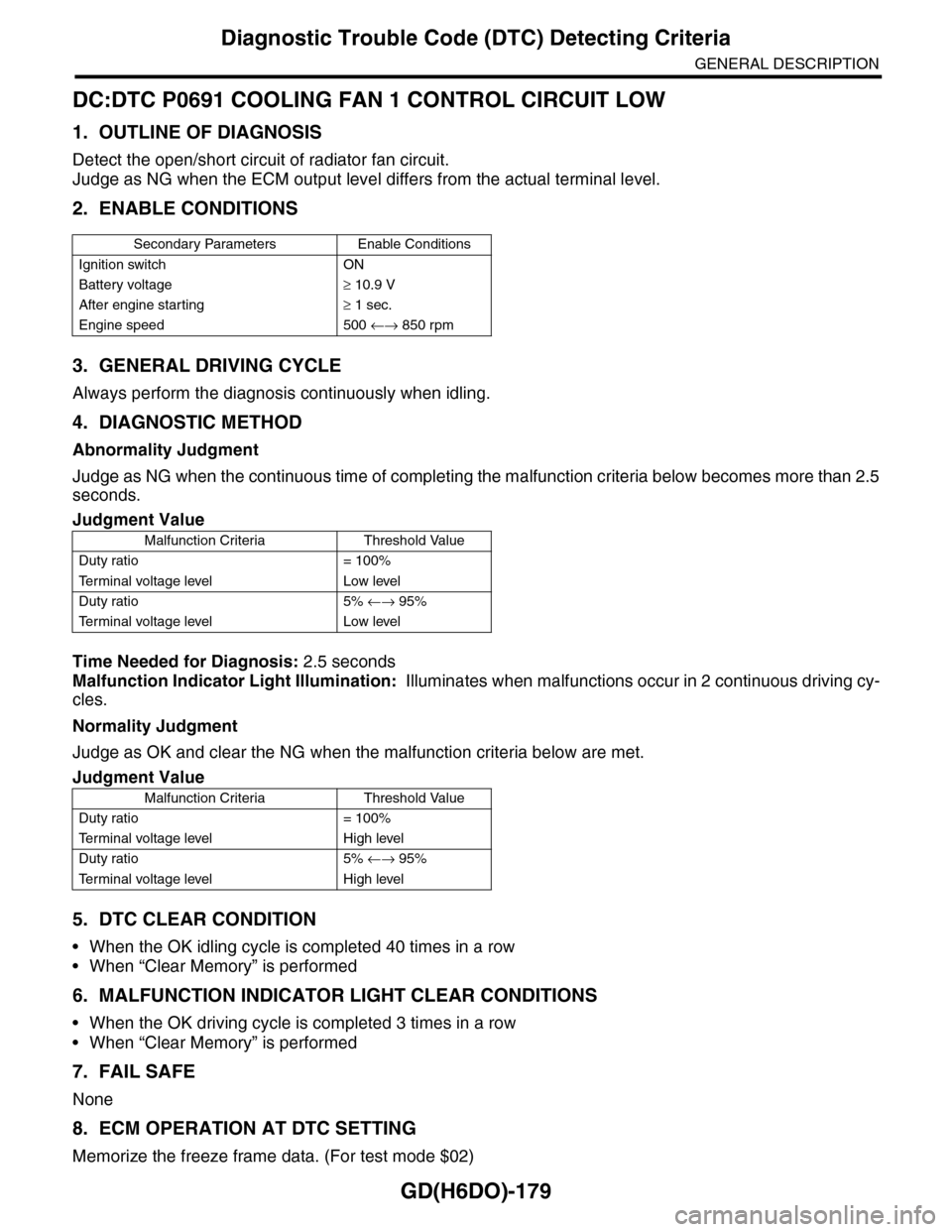
4. DIAGNOSTIC METHOD
Abnormality Judgment
Judge as NG when the continuous time of completing the malfunction criteria below becomes more than 2.5
seconds.
Time Needed for Diagnosis: 2.5 seconds
Malfunction Indicator Light Illumination: Illuminates when malfunctions occur in 2 continuous driving cy-
cles.
Normality Judgment
Judge as OK and clear the NG when the malfunction criteria below are met.
5. DTC CLEAR CONDITION
•When the OK idling cycle is completed 40 times in a row
•When “Clear Memory” is performed
6. MALFUNCTION INDICATOR LIGHT CLEAR CONDITIONS
•When the OK driving cycle is completed 3 times in a row
•When “Clear Memory” is performed
7. FAIL SAFE
None
8. ECM OPERATION AT DTC SETTING
Memorize the freeze frame data. (For test mode $02)
Secondary Parameters Enable Conditions
Ignition switch ON
Battery voltage≥ 10.9 V
After engine starting≥ 1 sec.
Engine speed 500 ←→ 850 rpm
Judgment Value
Malfunction Criteria Threshold Value
Duty ratio = 100%
Te r m i n a l v o l t a g e l e v e l L o w l e v e l
Duty ratio 5% ←→ 95%
Te r m i n a l v o l t a g e l e v e l L o w l e v e l
Judgment Value
Malfunction Criteria Threshold Value
Duty ratio = 100%
Te r m i n a l v o l t a g e l e v e l H i g h l e v e l
Duty ratio 5% ←→ 95%
Te r m i n a l v o l t a g e l e v e l H i g h l e v e l
Page 1792 of 2453
GD(H6DO)-180
Diagnostic Trouble Code (DTC) Detecting Criteria
GENERAL DESCRIPTION
DD:DTC P0692 COOLING FAN 1 CONTROL CIRCUIT HIGH
1. OUTLINE OF DIAGNOSIS
Detect the open/short circuit of radiator fan circuit.
Judge as NG when the ECM output level differs from the actual terminal level.
2. ENABLE CONDITIONS
3. GENERAL DRIVING CYCLE
Always perform the diagnosis continuously when idling.
4. DIAGNOSTIC METHOD
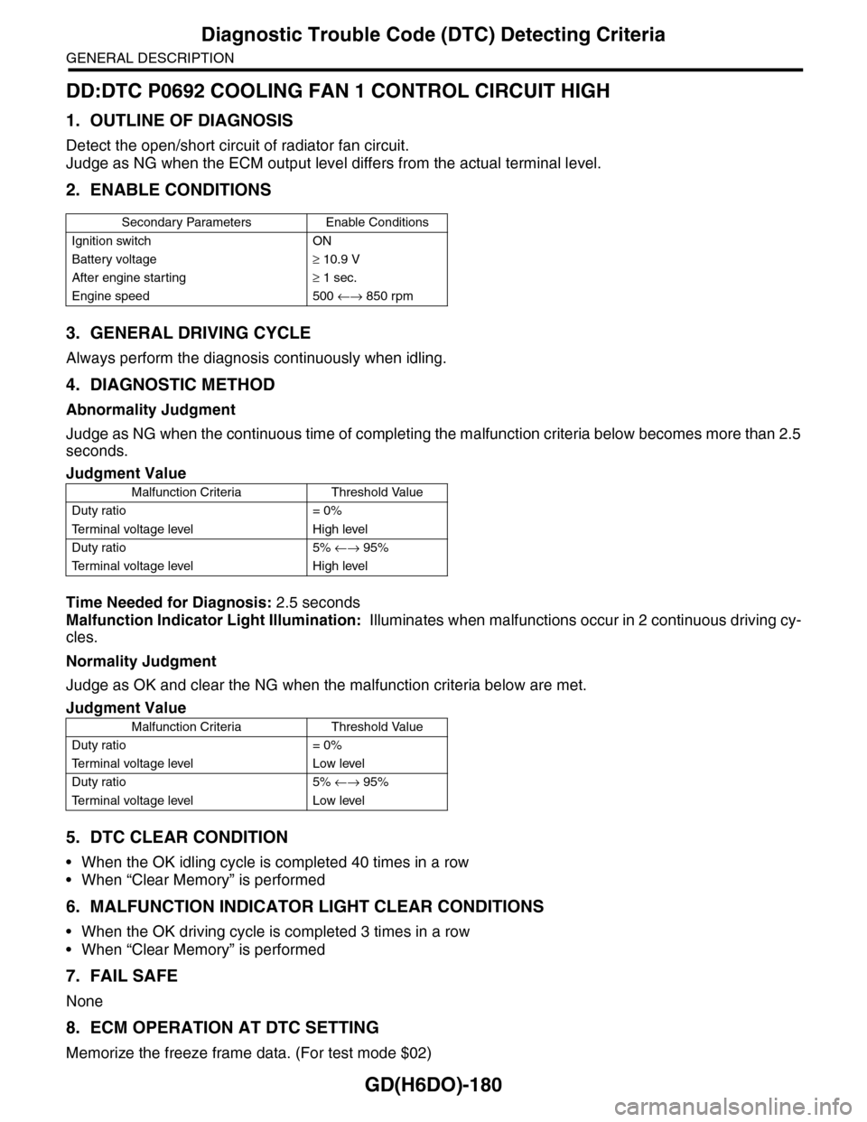
Abnormality Judgment
Judge as NG when the continuous time of completing the malfunction criteria below becomes more than 2.5
seconds.
Time Needed for Diagnosis: 2.5 seconds
Malfunction Indicator Light Illumination: Illuminates when malfunctions occur in 2 continuous driving cy-
cles.
Normality Judgment
Judge as OK and clear the NG when the malfunction criteria below are met.
5. DTC CLEAR CONDITION
•When the OK idling cycle is completed 40 times in a row
•When “Clear Memory” is performed
6. MALFUNCTION INDICATOR LIGHT CLEAR CONDITIONS
•When the OK driving cycle is completed 3 times in a row
•When “Clear Memory” is performed
7. FAIL SAFE
None
8. ECM OPERATION AT DTC SETTING
Memorize the freeze frame data. (For test mode $02)
Secondary Parameters Enable Conditions
Ignition switch ON
Battery voltage≥ 10.9 V
After engine starting≥ 1 sec.
Engine speed 500 ←→ 850 rpm
Judgment Value
Malfunction Criteria Threshold Value
Duty ratio = 0%
Te r m i n a l v o l t a g e l e v e l H i g h l e v e l
Duty ratio 5% ←→ 95%
Te r m i n a l v o l t a g e l e v e l H i g h l e v e l
Judgment Value
Malfunction Criteria Threshold Value
Duty ratio = 0%
Te r m i n a l v o l t a g e l e v e l L o w l e v e l
Duty ratio 5% ←→ 95%
Te r m i n a l v o l t a g e l e v e l L o w l e v e l
Page 1801 of 2453
GD(H6DO)-189
Diagnostic Trouble Code (DTC) Detecting Criteria
GENERAL DESCRIPTION
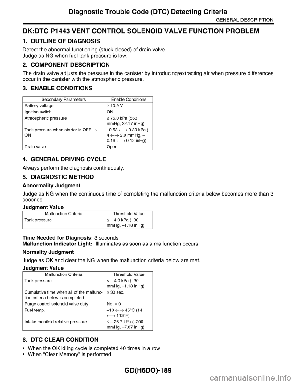
DK:DTC P1443 VENT CONTROL SOLENOID VALVE FUNCTION PROBLEM
1. OUTLINE OF DIAGNOSIS
Detect the abnormal functioning (stuck closed) of drain valve.
Judge as NG when fuel tank pressure is low.
2. COMPONENT DESCRIPTION
The drain valve adjusts the pressure in the canister by introducing/extracting air when pressure differences
occur in the canister with the atmospheric pressure.
3. ENABLE CONDITIONS
4. GENERAL DRIVING CYCLE
Always perform the diagnosis continuously.
5. DIAGNOSTIC METHOD
Abnormality Judgment
Judge as NG when the continuous time of completing the malfunction criteria below becomes more than 3
seconds.
Time Needed for Diagnosis: 3 seconds
Malfunction Indicator Light: Illuminates as soon as a malfunction occurs.
Normality Judgment
Judge as OK and clear the NG when the malfunction criteria below are met.
6. DTC CLEAR CONDITION
•When the OK idling cycle is completed 40 times in a row
•When “Clear Memory” is performed
Secondary Parameters Enable Conditions
Battery voltage≥ 10.9 V
Ignition switch ON
Atmospheric pressure≥ 75.0 kPa (563
mmHg, 22.17 inHg)
Ta n k p r e s s u r e w h e n s t a r t e r i s O F F →
ON
–0.53 ←→ 0.39 kPa (–
4 ←→ 2.9 mmHg, –
0.16 ←→ 0.12 inHg)
Drain valve Open
Judgment Value
Malfunction Criteria Threshold Value
Ta n k p r e s s u r e≤ – 4.0 kPa (–30
mmHg, –1.18 inHg)
Judgment Value
Malfunction Criteria Threshold Value
Ta n k p r e s s u r e > – 4 . 0 k P a ( – 3 0
mmHg, –1.18 inHg)
Cumulative time when all of the malfunc-
tion criteria below is completed.
≥ 30 sec.
Purge control solenoid valve duty Not = 0
Fuel temp. –10 ←→ 45°C (14
←→ 113°F)
Intake manifold relative pressure≤ – 26.7 kPa (–200
mmHg, –7.87 inHg)
Page 1829 of 2453
GD(H6DO)-217
Diagnostic Trouble Code (DTC) Detecting Criteria
GENERAL DESCRIPTION
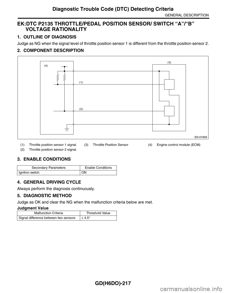
EK:DTC P2135 THROTTLE/PEDAL POSITION SENSOR/ SWITCH “A”/“B”
VOLTAGE RATIONALITY
1. OUTLINE OF DIAGNOSIS
Judge as NG when the signal level of throttle position sensor 1 is different from the throttle position sensor 2.
2. COMPONENT DESCRIPTION
3. ENABLE CONDITIONS
4. GENERAL DRIVING CYCLE
Always perform the diagnosis continuously.
5. DIAGNOSTIC METHOD
Judge as OK and clear the NG when the malfunction criteria below are met.
(1) Throttle position sensor 1 signal. (3) Throttle Position Sensor (4) Engine control module (ECM)
(2) Throttle position sensor 2 signal.
Secondary Parameters Enable Conditions
Ignition switch ON
Judgment Value
Malfunction Criteria Threshold Value
Signal difference between two sensors≤ 4.5°
EN-01859
(1)
(2)
(3)(4)
Page 1830 of 2453
GD(H6DO)-218
Diagnostic Trouble Code (DTC) Detecting Criteria
GENERAL DESCRIPTION
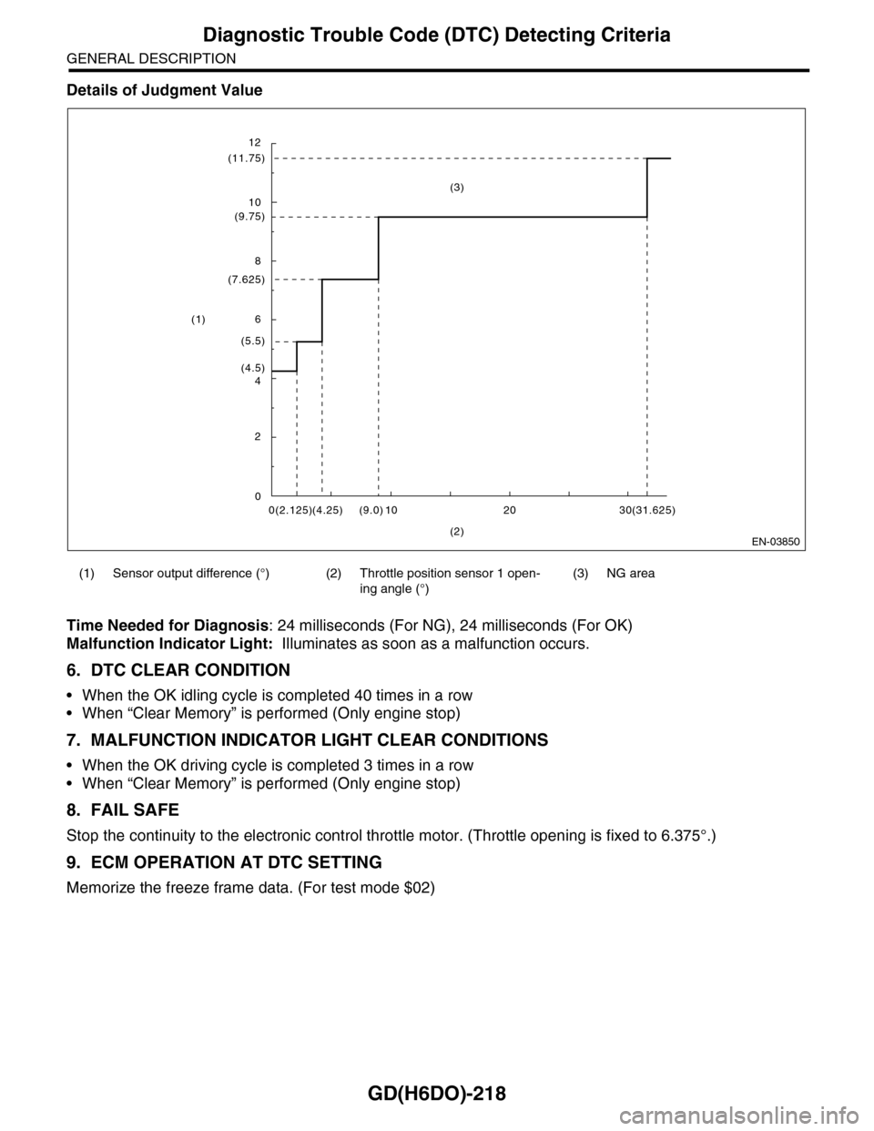
Details of Judgment Value
Time Needed for Diagnosis: 24 milliseconds (For NG), 24 milliseconds (For OK)
Malfunction Indicator Light: Illuminates as soon as a malfunction occurs.
6. DTC CLEAR CONDITION
•When the OK idling cycle is completed 40 times in a row
•When “Clear Memory” is performed (Only engine stop)
7. MALFUNCTION INDICATOR LIGHT CLEAR CONDITIONS
•When the OK driving cycle is completed 3 times in a row
•When “Clear Memory” is performed (Only engine stop)
8. FAIL SAFE
Stop the continuity to the electronic control throttle motor. (Throttle opening is fixed to 6.375°.)
9. ECM OPERATION AT DTC SETTING
Memorize the freeze frame data. (For test mode $02)
(1) Sensor output difference (°) (2) Throttle position sensor 1 open-
ing angle (°)
(3) NG area
EN-03850
12
(11.75)
10
(9.75)
8
(7.625)
6
(5.5)
(4.5)4
2
00(2.125)(4.25) 10(9.0) 20 30(31.625)
(2)
(1)
(3)
Page 1831 of 2453
GD(H6DO)-219
Diagnostic Trouble Code (DTC) Detecting Criteria
GENERAL DESCRIPTION
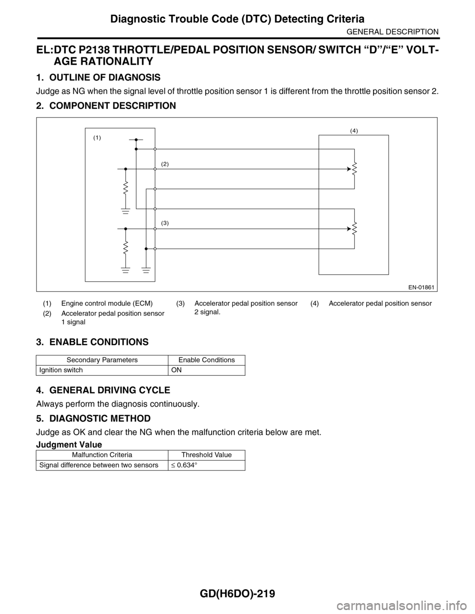
EL:DTC P2138 THROTTLE/PEDAL POSITION SENSOR/ SWITCH “D”/“E” VOLT-
AGE RATIONALITY
1. OUTLINE OF DIAGNOSIS
Judge as NG when the signal level of throttle position sensor 1 is different from the throttle position sensor 2.
2. COMPONENT DESCRIPTION
3. ENABLE CONDITIONS
4. GENERAL DRIVING CYCLE
Always perform the diagnosis continuously.
5. DIAGNOSTIC METHOD
Judge as OK and clear the NG when the malfunction criteria below are met.
(1) Engine control module (ECM) (3)
Accelerator pedal position sensor
2 signal.
(4) Accelerator pedal position sensor
(2) Accelerator pedal position sensor
1 signal
Secondary Parameters Enable Conditions
Ignition switch ON
Judgment Value
Malfunction Criteria Threshold Value
Signal difference between two sensors≤ 0.634°
EN-01861
(2)
(3)
(4)(1)
Page 1832 of 2453

GD(H6DO)-220
Diagnostic Trouble Code (DTC) Detecting Criteria
GENERAL DESCRIPTION
Details of Judgment Value
Time Needed for Diagnosis:
•116 milliseconds (For NG)
•1000 milliseconds (For OK)
Malfunction Indicator Light: Illuminates as soon as a malfunction occurs.
6. DTC CLEAR CONDITION
•When the OK idling cycle is completed 40 times in a row
•When “Clear Memory” is performed
7. MALFUNCTION INDICATOR LIGHT CLEAR CONDITIONS
•When the OK driving cycle is completed 3 times in a row
•When “Clear Memory” is performed
8. FAIL SAFE
Throttle opening is fixed to 6.375°.
9. ECM OPERATION AT DTC SETTING
Memorize the freeze frame data. (For test mode $02)
(1) Sensor output difference (°) (2) Throttle position sensor 2 open-
ing angle (°)
(3) NG area
EN-03851
0
(0.916)
(0.634)
(1.297)
(1)
(3)
0(0.6)
(2)
(1.2)(4.0)(2.0)
(2.492)
(1.947)
Page 1833 of 2453
GD(H6DO)-221
Diagnostic Trouble Code (DTC) Detecting Criteria
GENERAL DESCRIPTION
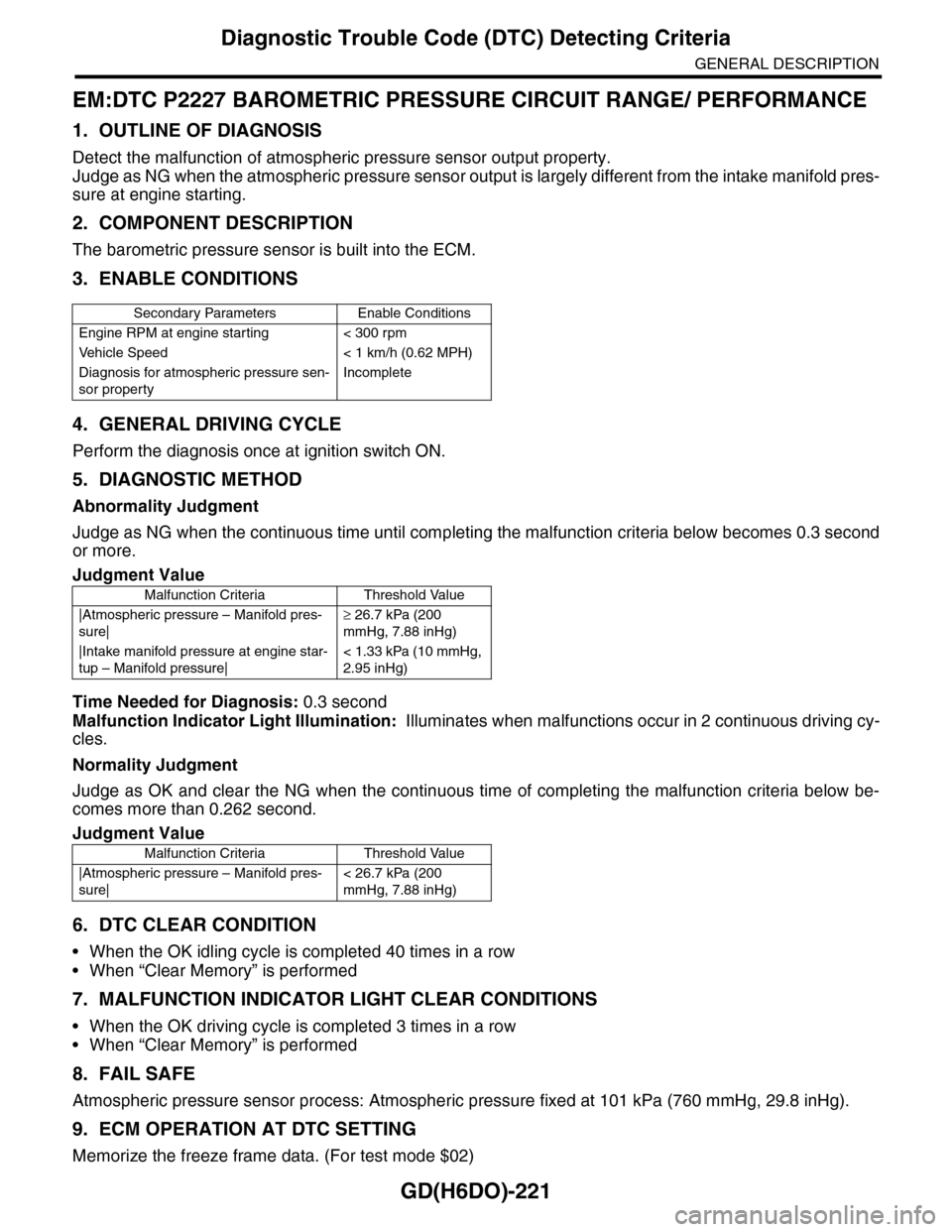
EM:DTC P2227 BAROMETRIC PRESSURE CIRCUIT RANGE/ PERFORMANCE
1. OUTLINE OF DIAGNOSIS
Detect the malfunction of atmospheric pressure sensor output property.
Judge as NG when the atmospheric pressure sensor output is largely different from the intake manifold pres-
sure at engine starting.
2. COMPONENT DESCRIPTION
The barometric pressure sensor is built into the ECM.
3. ENABLE CONDITIONS
4. GENERAL DRIVING CYCLE
Perform the diagnosis once at ignition switch ON.
5. DIAGNOSTIC METHOD
Abnormality Judgment
Judge as NG when the continuous time until completing the malfunction criteria below becomes 0.3 second
or more.
Time Needed for Diagnosis: 0.3 second
Malfunction Indicator Light Illumination: Illuminates when malfunctions occur in 2 continuous driving cy-
cles.
Normality Judgment
Judge as OK and clear the NG when the continuous time of completing the malfunction criteria below be-
comes more than 0.262 second.
6. DTC CLEAR CONDITION
•When the OK idling cycle is completed 40 times in a row
•When “Clear Memory” is performed
7. MALFUNCTION INDICATOR LIGHT CLEAR CONDITIONS
•When the OK driving cycle is completed 3 times in a row
•When “Clear Memory” is performed
8. FAIL SAFE
Atmospheric pressure sensor process: Atmospheric pressure fixed at 101 kPa (760 mmHg, 29.8 inHg).
9. ECM OPERATION AT DTC SETTING
Memorize the freeze frame data. (For test mode $02)
Secondary Parameters Enable Conditions
Engine RPM at engine starting < 300 rpm
Ve h i c l e S p e e d < 1 k m / h ( 0 . 6 2 M P H )
Diagnosis for atmospheric pressure sen-
sor property
Incomplete
Judgment Value
Malfunction Criteria Threshold Value
|Atmospheric pressure – Manifold pres-
sure|
≥ 26.7 kPa (200
mmHg, 7.88 inHg)
|Intake manifold pressure at engine star-
tup – Manifold pressure|
< 1.33 kPa (10 mmHg,
2.95 inHg)
Judgment Value
Malfunction Criteria Threshold Value
|Atmospheric pressure – Manifold pres-
sure|
< 26.7 kPa (200
mmHg, 7.88 inHg)