steering SUBARU TRIBECA 2009 1.G Service Workshop Manual
[x] Cancel search | Manufacturer: SUBARU, Model Year: 2009, Model line: TRIBECA, Model: SUBARU TRIBECA 2009 1.GPages: 2453, PDF Size: 46.32 MB
Page 1898 of 2453

ME(H6DO)-32
Engine Assembly
MECHANICAL
10.Engine Assembly
A: REMOVAL
1) Set the vehicle on a lift.
2) Change the bolt mounting position from (A) to
(B), then completely open the front hood.
3) Remove the collector cover.
4) Collect the refrigerant from A/C system.
cedure.>
5) Release the fuel pressure.
6) Remove the battery from vehicle.
7) Remove the air intake duct, air cleaner case and
air intake chamber.
8) Remove the engine front cover.
9) Remove the radiator from the vehicle.
NOTE:
Protect the condenser so that it will not be dam-
aged.
10) Remove the fuel hose bracket.
11) Remove the V-belts.
12) Disconnect the A/C pressure hoses from A/C
compressor.
13) Remove the engine ground terminal.
14) Disconnect the following connector.
(1) Engine harness connectors
(2) Generator connector, terminal and A/C
compressor connector
(3) Power steering switch connector
ME-02652
(A)
(B)
CO-02176
ME-02653
ME-00476
ME-02654
Page 1899 of 2453
ME(H6DO)-33
Engine Assembly
MECHANICAL
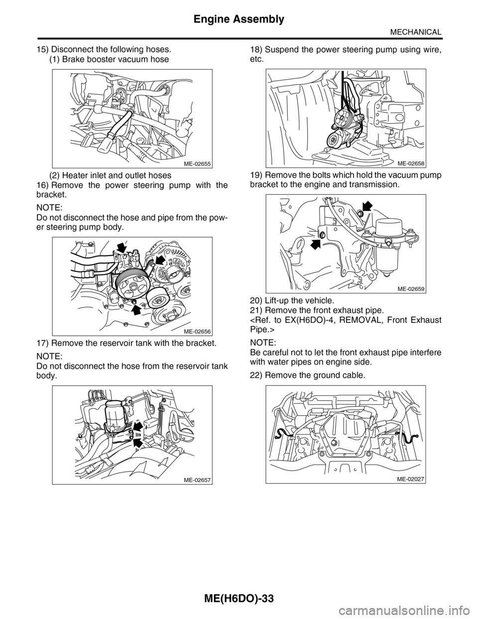
15) Disconnect the following hoses.
(1) Brake booster vacuum hose
(2) Heater inlet and outlet hoses
16) Remove the power steering pump with the
bracket.
NOTE:
Do not disconnect the hose and pipe from the pow-
er steering pump body.
17) Remove the reservoir tank with the bracket.
NOTE:
Do not disconnect the hose from the reservoir tank
body.
18) Suspend the power steering pump using wire,
etc.
19) Remove the bolts which hold the vacuum pump
bracket to the engine and transmission.
20) Lift-up the vehicle.
21) Remove the front exhaust pipe.
NOTE:
Be careful not to let the front exhaust pipe interfere
with water pipes on engine side.
22) Remove the ground cable.
ME-02655
ME-02656
ME-02657
ME-02658
ME-02659
ME-02027
Page 1903 of 2453
ME(H6DO)-37
Engine Assembly
MECHANICAL
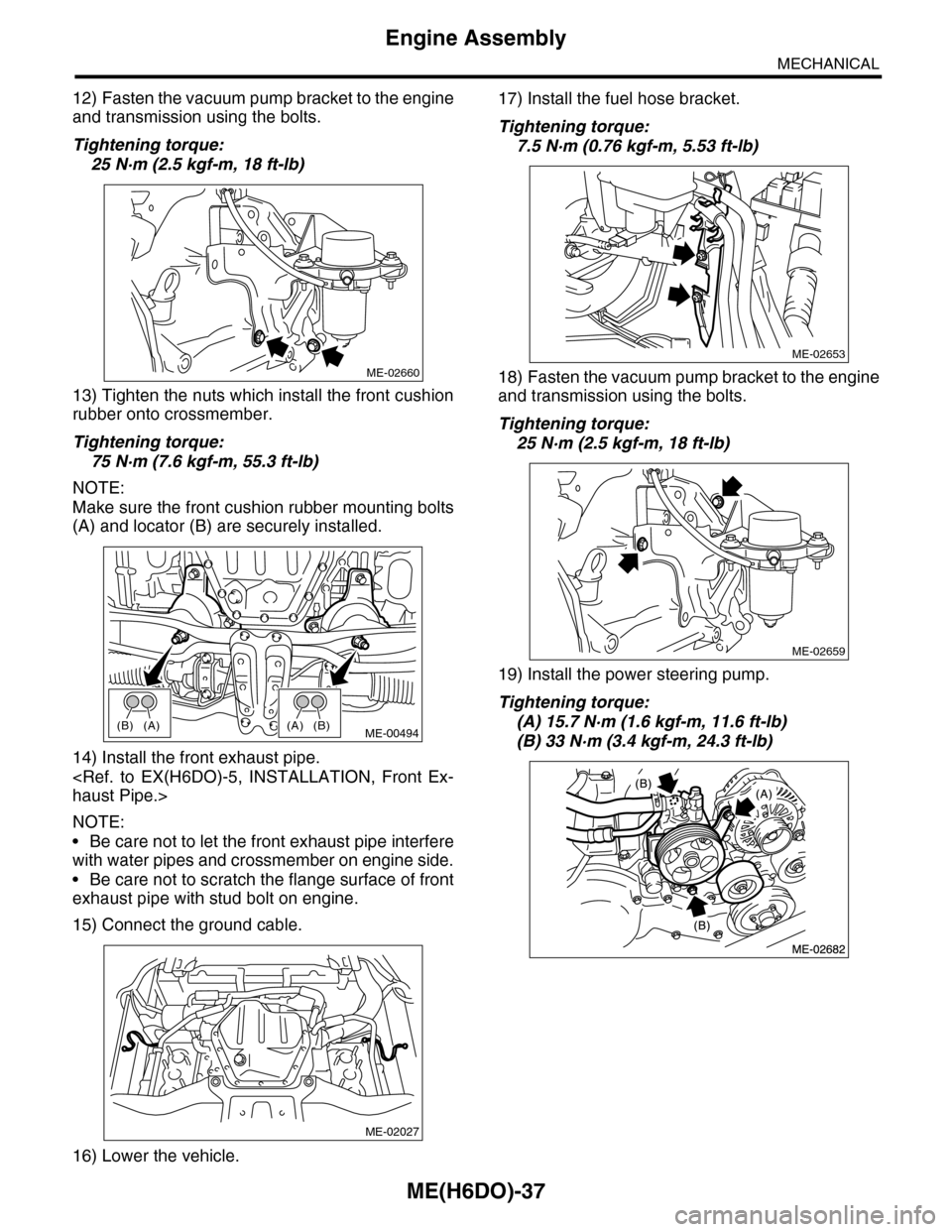
12) Fasten the vacuum pump bracket to the engine
and transmission using the bolts.
Tightening torque:
25 N·m (2.5 kgf-m, 18 ft-lb)
13) Tighten the nuts which install the front cushion
rubber onto crossmember.
Tightening torque:
75 N·m (7.6 kgf-m, 55.3 ft-lb)
NOTE:
Make sure the front cushion rubber mounting bolts
(A) and locator (B) are securely installed.
14) Install the front exhaust pipe.
NOTE:
•Be care not to let the front exhaust pipe interfere
with water pipes and crossmember on engine side.
•Be care not to scratch the flange surface of front
exhaust pipe with stud bolt on engine.
15) Connect the ground cable.
16) Lower the vehicle.
17) Install the fuel hose bracket.
Tightening torque:
7.5 N·m (0.76 kgf-m, 5.53 ft-lb)
18) Fasten the vacuum pump bracket to the engine
and transmission using the bolts.
Tightening torque:
25 N·m (2.5 kgf-m, 18 ft-lb)
19) Install the power steering pump.
Tightening torque:
(A) 15.7 N·m (1.6 kgf-m, 11.6 ft-lb)
(B) 33 N·m (3.4 kgf-m, 24.3 ft-lb)
ME-02660
(A)(B)(B)(A)ME-00494
ME-02027
ME-02653
ME-02659
Page 1904 of 2453
ME(H6DO)-38
Engine Assembly
MECHANICAL
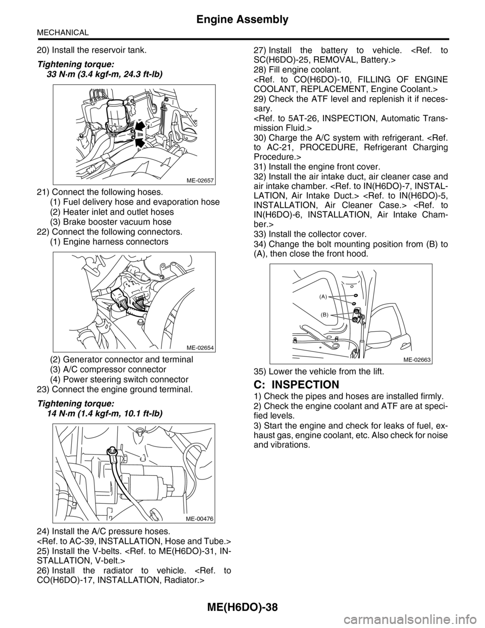
20) Install the reservoir tank.
Tightening torque:
33 N·m (3.4 kgf-m, 24.3 ft-lb)
21) Connect the following hoses.
(1) Fuel delivery hose and evaporation hose
(2) Heater inlet and outlet hoses
(3) Brake booster vacuum hose
22) Connect the following connectors.
(1) Engine harness connectors
(2) Generator connector and terminal
(3) A/C compressor connector
(4) Power steering switch connector
23) Connect the engine ground terminal.
Tightening torque:
14 N·m (1.4 kgf-m, 10.1 ft-lb)
24) Install the A/C pressure hoses.
25) Install the V-belts.
26) Install the radiator to vehicle.
27) Install the battery to vehicle.
28) Fill engine coolant.
29) Check the ATF level and replenish it if neces-
sary.
30) Charge the A/C system with refrigerant.
Procedure.>
31) Install the engine front cover.
32) Install the air intake duct, air cleaner case and
air intake chamber.
ber.>
33) Install the collector cover.
34) Change the bolt mounting position from (B) to
(A), then close the front hood.
35) Lower the vehicle from the lift.
C: INSPECTION
1) Check the pipes and hoses are installed firmly.
2) Check the engine coolant and ATF are at speci-
fied levels.
3) Start the engine and check for leaks of fuel, ex-
haust gas, engine coolant, etc. Also check for noise
and vibrations.
ME-02657
ME-02654
ME-00476
ME-02663
(A)
(B)
Page 1986 of 2453
PM-3
Schedule
PERIODIC MAINTENANCE SERVICES
2. Schedule
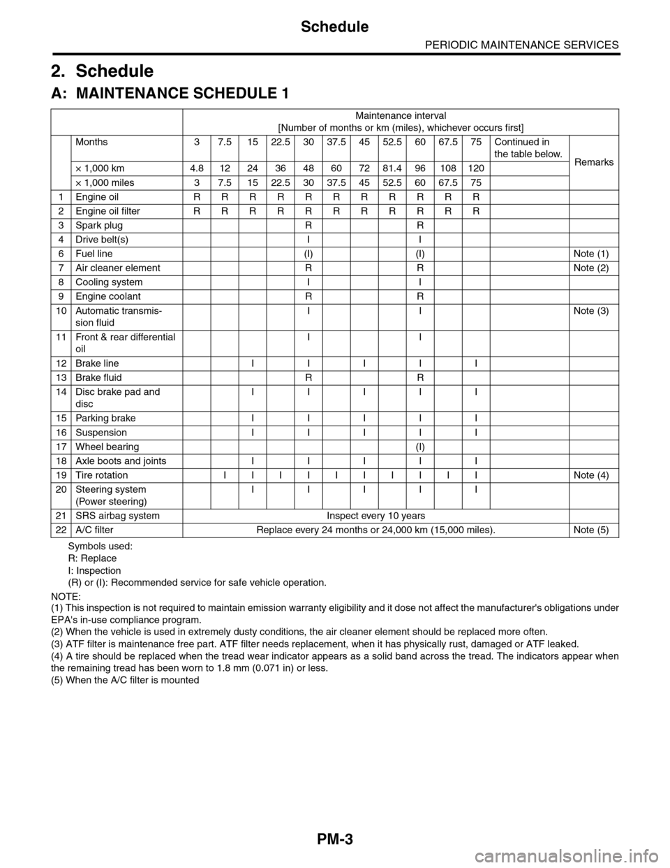
A: MAINTENANCE SCHEDULE 1
Symbols used:
R: Replace
I: Inspection
(R) or (I): Recommended service for safe vehicle operation.
NOTE:(1) This inspection is not required to maintain emission warranty eligibility and it dose not affect the manufacturer's obligations under
EPA's in-use compliance program.
(2) When the vehicle is used in extremely dusty conditions, the air cleaner element should be replaced more often.
(3) ATF filter is maintenance free part. ATF filter needs replacement, when it has physically rust, damaged or ATF leaked.
(4) A tire should be replaced when the tread wear indicator appears as a solid band across the tread. The indicators appear when
the remaining tread has been worn to 1.8 mm (0.071 in) or less.
(5) When the A/C filter is mounted
Maintenance interval
[Number of months or km (miles), whichever occurs first]
Months 3 7.51522.53037.54552.56067.575Continued in
the table below.Remarks× 1,000 km 4.8 12 24 36 48 60 72 81.4 96 108 120
× 1,000 miles 3 7.5 15 22.5 30 37.5 45 52.5 60 67.5 75
1Engine oil R R R R R R R R R R R
2Engine oil filter R R R R R R R R R R R
3Spark plug R R
4Drive belt(s) I I
6Fuel line (I) (I) Note (1)
7Air cleaner element R R Note (2)
8Cooling system I I
9Engine coolant R R
10 Automatic transmis-
sion fluid
I I Note (3)
11 Front & rear differential
oil
I I
12 Brake line I I I I I
13 Brake fluid R R
14 Disc brake pad and
disc
I I I I I
15 Parking brake I I I I I
16 Suspension I I I I I
17 Wheel bearing (I)
18 Axle boots and joints I I I I I
19 Tire rotation I I I I I I I I I I Note (4)
20 Steering system
(Power steering)
I I I I I
21 SRS airbag system Inspect every 10 years
22 A/C filter Replace every 24 months or 24,000 km (15,000 miles). Note (5)
Page 1987 of 2453
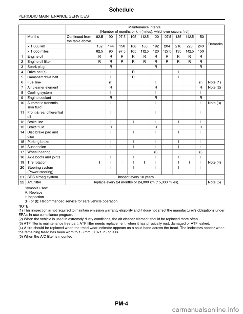
PM-4
Schedule
PERIODIC MAINTENANCE SERVICES
Symbols used:
R: Replace
I: Inspection
(R) or (I): Recommended service for safe vehicle operation.
NOTE:(1) This inspection is not required to maintain emission warranty eligibility and it dose not affect the manufacturer's obligations under
EPA's in-use compliance program.
(2) When the vehicle is used in extremely dusty conditions, the air cleaner element should be replaced more often.
(3) ATF filter is maintenance free part. ATF filter needs replacement, when it has physically rust, damaged or ATF leaked.
(4) A tire should be replaced when the tread wear indicator appears as a solid band across the tread. The indicators appear when
the remaining tread has been worn to 1.8 mm (0.071 in) or less.
(5) When the A/C filter is mounted
Maintenance interval
[Number of months or km (miles), whichever occurs first]
Months Continued from
the table above.
82.5 90 97.5 105112.5120127.5135142.5150
Remarks× 1,000 km 132 144 156 168 180 192 204 216 228 240
× 1,000 miles 82.5 90 97.5 105112.5120127.5135142.5150
1Engine oil R R R R R R R R R R
2Engine oil filter R R R R R R R R R R
3Spark plug R R R
4Drive belt(s) I R I
5Camshaft drive belt I R I
6Fuel line (I) I (I) Note (1)
7Air cleaner element R R R Note (2)
8Cooling system I I I
9Engine coolant R R R
10 Automatic transmis-
sion fluid
I I INote (3)
11 Front & rear differential
oil
I I I
12 Brake line I I I I I
13 Brake fluid R R R
14 Disc brake pad and
disc
I I I I I
15 Parking brake I I I I I
16 Suspension I I I I I
17 Wheel bearing (I) (I)
18 Axle boots and joints I I I I I
19 Tire rotation I I I I I I I I I I Note (4)
20 Steering system
(Power steering)
I I I I I
21 SRS airbag system Inspect every 10 years
22 A/C filter Replace every 24 months or 24,000 km (15,000 miles). Note (5)
Page 1988 of 2453
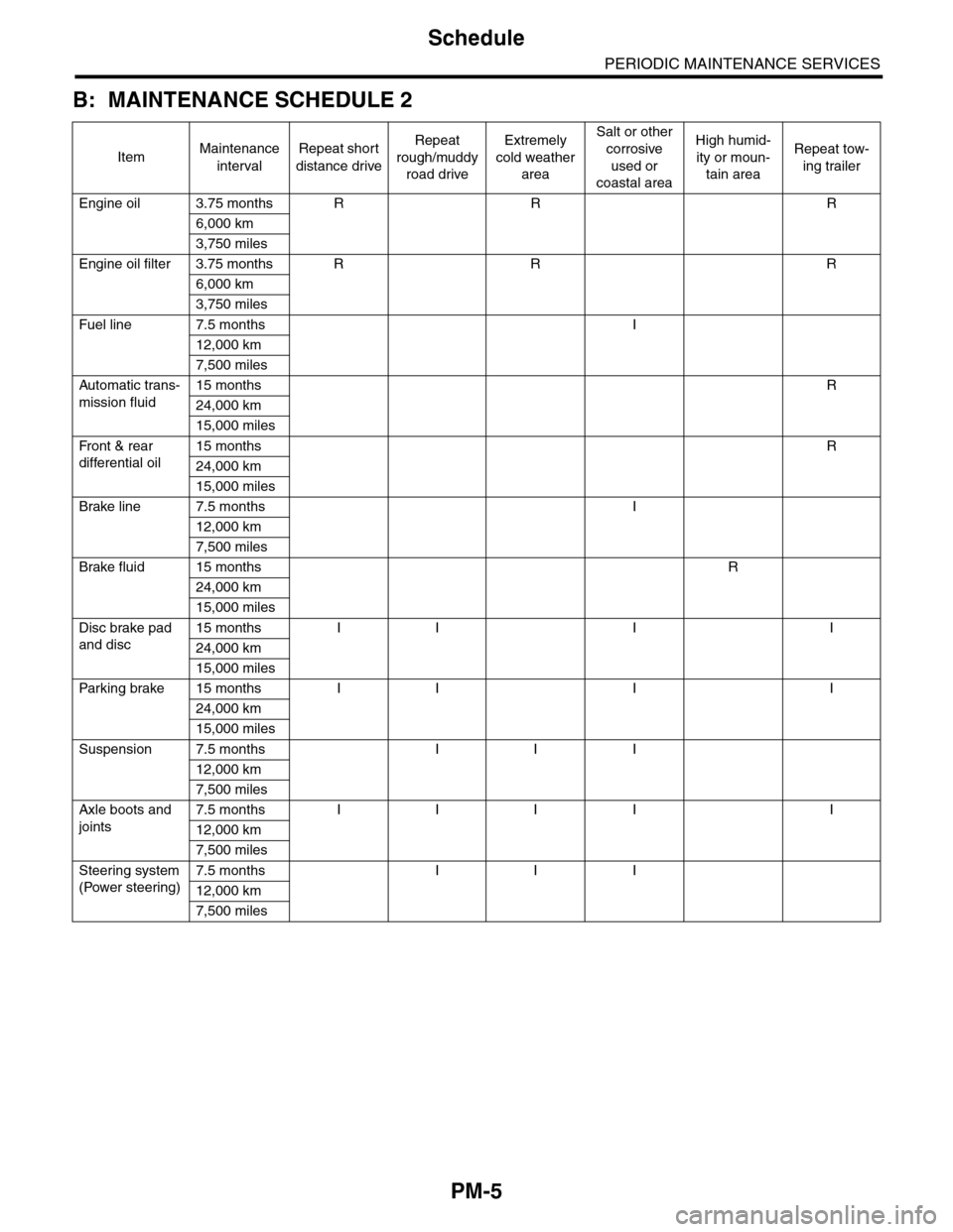
PM-5
Schedule
PERIODIC MAINTENANCE SERVICES
B: MAINTENANCE SCHEDULE 2
ItemMaintenance
interval
Repeat short
distance drive
Repeat
rough/muddy
road drive
Extremely
cold weather
area
Salt or other
corrosive
used or
coastal area
High humid-
ity or moun-
tain area
Repeat tow-
ing trailer
Engine oil 3.75 months R R R
6,000 km
3,750 miles
Engine oil filter 3.75 months R R R
6,000 km
3,750 miles
Fuel line 7.5 months I
12,000 km
7,500 miles
Automatic trans-
mission fluid
15 months R
24,000 km
15,000 miles
Fr o nt & r ea r
differential oil
15 months R
24,000 km
15,000 miles
Brake line 7.5 months I
12,000 km
7,500 miles
Brake fluid 15 months R
24,000 km
15,000 miles
Disc brake pad
and disc
15 months I I I I
24,000 km
15,000 miles
Par king brake 15 months I I I I
24,000 km
15,000 miles
Suspension 7.5 months I I I
12,000 km
7,500 miles
Axle boots and
joints
7.5 months I I I I I
12,000 km
7,500 miles
Steering system
(Power steering)
7.5 months I I I
12,000 km
7,500 miles
Page 1993 of 2453
PM-10
V-belt
PERIODIC MAINTENANCE SERVICES
6. V-belt
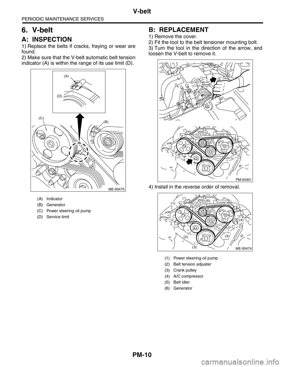
A: INSPECTION
1) Replace the belts if cracks, fraying or wear are
found.
2) Make sure that the V-belt automatic belt tension
indicator (A) is within the range of its use limit (D).
B: REPLACEMENT
1) Remove the cover.
2) Fit the tool to the belt tensioner mounting bolt.
3) Turn the tool in the direction of the arrow, and
loosen the V-belt to remove it.
4) Install in the reverse order of removal.
(A) Indicator
(B) Generator
(C) Power steering oil pump
(D) Service limit
(B)
(A)
(D)
(C)
ME-00475
(1) Power steering oil pump
(2) Belt tension adjuster
(3) Crank pulley
(4) A/C compressor
(5) Belt idler
(6) Generator
PM-00301
(1)(6)
(4)
(5)(2)
(3)ME-00474
Page 2003 of 2453
PM-20
Brake Line
PERIODIC MAINTENANCE SERVICES
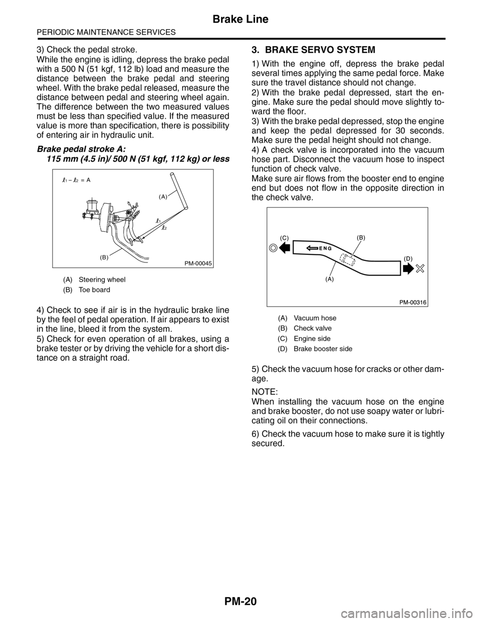
3) Check the pedal stroke.
While the engine is idling, depress the brake pedal
with a 500 N (51 kgf, 112 lb) load and measure the
distance between the brake pedal and steering
wheel. With the brake pedal released, measure the
distance between pedal and steering wheel again.
The difference between the two measured values
must be less than specified value. If the measured
value is more than specification, there is possibility
of entering air in hydraulic unit.
Brake pedal stroke A:
115 mm (4.5 in)/ 500 N (51 kgf, 112 kg) or less
4) Check to see if air is in the hydraulic brake line
by the feel of pedal operation. If air appears to exist
in the line, bleed it from the system.
5) Check for even operation of all brakes, using a
brake tester or by driving the vehicle for a short dis-
tance on a straight road.
3. BRAKE SERVO SYSTEM
1) With the engine off, depress the brake pedal
several times applying the same pedal force. Make
sure the travel distance should not change.
2) With the brake pedal depressed, start the en-
gine. Make sure the pedal should move slightly to-
ward the floor.
3) With the brake pedal depressed, stop the engine
and keep the pedal depressed for 30 seconds.
Make sure the pedal height should not change.
4) A check valve is incorporated into the vacuum
hose part. Disconnect the vacuum hose to inspect
function of check valve.
Make sure air flows from the booster end to engine
end but does not flow in the opposite direction in
the check valve.
5) Check the vacuum hose for cracks or other dam-
age.
NOTE:
When installing the vacuum hose on the engine
and brake booster, do not use soapy water or lubri-
cating oil on their connections.
6) Check the vacuum hose to make sure it is tightly
secured.
(A) Steering wheel
(B) Toe board
PM-00045(B)
(A)
= A
1
12
2
(A) Vacuum hose
(B) Check valve
(C) Engine side
(D) Brake booster side
Page 2008 of 2453
PM-25
Suspension
PERIODIC MAINTENANCE SERVICES
4. WHEEL ALIGNMENT OF FRONT SUS-
PENSION
1) Check the alignment of front suspension to en-
sure that following items conform to standard val-
ues.
•Toe-in
•Camber
•Caster
•Steering angle
2) When the caster angle does not conform to ref-
erence obviously, visually inspect the following
components and replace deformed parts.
•Suspension components [Strut assembly, cross-
member, front arm, etc.]
•Parts connecting suspension and body
3) When the toe-in and camber are out of standard
value, adjust them so that they conform to standard
value.
4) When the right-and-left turning angles of tire are
out of standard, adjust to standard value.
5. WHEEL ALIGNMENT OF REAR SUS-
PENSION
1) Check the alignment of rear suspension to en-
sure that following items are within standard val-
ues.
•Toe-in
•Camber
•Thrust angle
2) When the camber angle does not conform to
standard value, visually inspect the following com-
ponents. If the deformation is observed, replace the
damaged parts.
•Suspension components [Shock absorber, rear
upper arm, front lateral link, rear lateral link, rear
trailing link, sub frame]
•Parts connecting suspension and body
3) When the toe-in and thrust angle are out of stan-
dard value, adjust them so that they conform to
standard value.
6. OIL LEAKAGE OF STRUT AND SHOCK
ABSORBER
Visually inspect the front strut and rear shock ab-
sorber for oil leakage. Replace the front strut and
rear shock absorber if oil leaks excessively.
7. TIGHTNESS OF BOLTS AND NUTS
Check the bolts and nuts for looseness. Retighten
the bolts and nuts to specified torque. If the self-
locking nuts and bolts are removed, replace them
with new ones.
•Front suspension
•Rear suspension
8. DAMAGE TO SUSPENSION PARTS
Check the following parts and the fastening portion
of the vehicle body for deformation or excessive
rusting which impairs the suspension. If necessary,
replace the damaged parts with new ones. If minor
rust formation, pitting, etc. are noted, remove the
rust and take rust prevention measure.
•Front suspension
•Front arm
•Crossmember
•Strut
•Rear suspension
•Upper arm
•Front lateral link
•Rear lateral link
•Rear trailing link
•Rear sub frame
•Shock absorber
•In the area where salt is sprayed to melt snow on
a road in winter, check suspension parts for dam-
age caused by rust every 12 months after lapse of
60 months. Take rust prevention measures as re-
quired.