engine oil SUBARU TRIBECA 2009 1.G Service Workshop Manual
[x] Cancel search | Manufacturer: SUBARU, Model Year: 2009, Model line: TRIBECA, Model: SUBARU TRIBECA 2009 1.GPages: 2453, PDF Size: 46.32 MB
Page 189 of 2453
ET-3
Audio System
ENTERTAINMENT
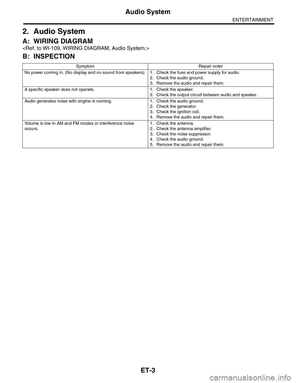
2. Audio System
A: WIRING DIAGRAM
B: INSPECTION
Symptom Repair order
No power coming in. (No display and no sound from speakers) 1. Check the fuse and power supply for audio.
2. Check the audio ground.
3. Remove the audio and repair them.
A specific speaker does not operate. 1. Check the speaker.
2. Check the output circuit between audio and speaker.
Audio generates noise with engine is r unning. 1. C heck the audio ground.
2. Check the generator.
3. Check the ignition coil.
4. Remove the audio and repair them.
Vo l u m e i s l o w i n A M a n d F M m o d e s o r i n t e r f e r e n c e n o i s e
occurs.
1. Check the antenna.
2. Check the antenna amplifier.
3. Check the noise suppressor.
4. Check the audio ground.
5. Remove the audio and repair them.
Page 340 of 2453
AC-14
General Description
HVAC SYSTEM (HEATER, VENTILATOR AND A/C)
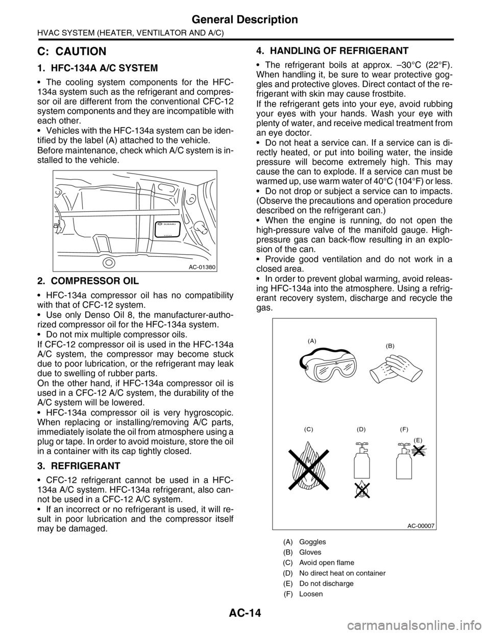
C: CAUTION
1. HFC-134A A/C SYSTEM
•The cooling system components for the HFC-
134a system such as the refrigerant and compres-
sor oil are different from the conventional CFC-12
system components and they are incompatible with
each other.
•Vehicles with the HFC-134a system can be iden-
tified by the label (A) attached to the vehicle.
Before maintenance, check which A/C system is in-
stalled to the vehicle.
2. COMPRESSOR OIL
•HFC-134a compressor oil has no compatibility
with that of CFC-12 system.
•Use only Denso Oil 8, the manufacturer-autho-
rized compressor oil for the HFC-134a system.
•Do not mix multiple compressor oils.
If CFC-12 compressor oil is used in the HFC-134a
A/C system, the compressor may become stuck
due to poor lubrication, or the refrigerant may leak
due to swelling of rubber parts.
On the other hand, if HFC-134a compressor oil is
used in a CFC-12 A/C system, the durability of the
A/C system will be lowered.
•HFC-134a compressor oil is very hygroscopic.
When replacing or installing/removing A/C parts,
immediately isolate the oil from atmosphere using a
plug or tape. In order to avoid moisture, store the oil
in a container with its cap tightly closed.
3. REFRIGERANT
•CFC-12 refrigerant cannot be used in a HFC-
134a A/C system. HFC-134a refrigerant, also can-
not be used in a CFC-12 A/C system.
•If an incorrect or no refrigerant is used, it will re-
sult in poor lubrication and the compressor itself
may be damaged.
4. HANDLING OF REFRIGERANT
•The refrigerant boils at approx. –30°C (22°F).
When handling it, be sure to wear protective gog-
gles and protective gloves. Direct contact of the re-
frigerant with skin may cause frostbite.
If the refrigerant gets into your eye, avoid rubbing
your eyes with your hands. Wash your eye with
plenty of water, and receive medical treatment from
an eye doctor.
•Do not heat a service can. If a service can is di-
rectly heated, or put into boiling water, the inside
pressure will become extremely high. This may
cause the can to explode. If a service can must be
warmed up, use warm water of 40°C (104°F) or less.
•Do not drop or subject a service can to impacts.
(Observe the precautions and operation procedure
described on the refrigerant can.)
•When the engine is running, do not open the
high-pressure valve of the manifold gauge. High-
pressure gas can back-flow resulting in an explo-
sion of the can.
•Provide good ventilation and do not work in a
closed area.
•In order to prevent global warming, avoid releas-
ing HFC-134a into the atmosphere. Using a refrig-
erant recovery system, discharge and recycle the
gas.
AC-01380
(A) Goggles
(B) Gloves
(C) Avoid open flame
(D) No direct heat on container
(E) Do not discharge
(F) Loosen
(A)(B)
(C) (D)
(E)
(F)
AC-00007
Page 346 of 2453
AC-20
Refrigerant Recovery Procedure
HVAC SYSTEM (HEATER, VENTILATOR AND A/C)
3. Refrigerant Recovery Proce-
dure
A: PROCEDURE
CAUTION:
•During operation, be sure to wear protective
goggles and protective gloves.
•Connect the refrigerant recovery system with
the manifold gauge set to discharge the refrig-
erant from the A/C system and recycle the gas.
•When recycling the discharged refrigerant,
keep service cans on hand. Because the recov-
ery rate with the recovery system is approx.
90%, service cans are necessary to charge the
refrigerant.
•Follow the detailed operation procedure de-
scribed in the operation manual attached to the
refrigerant recovery system.
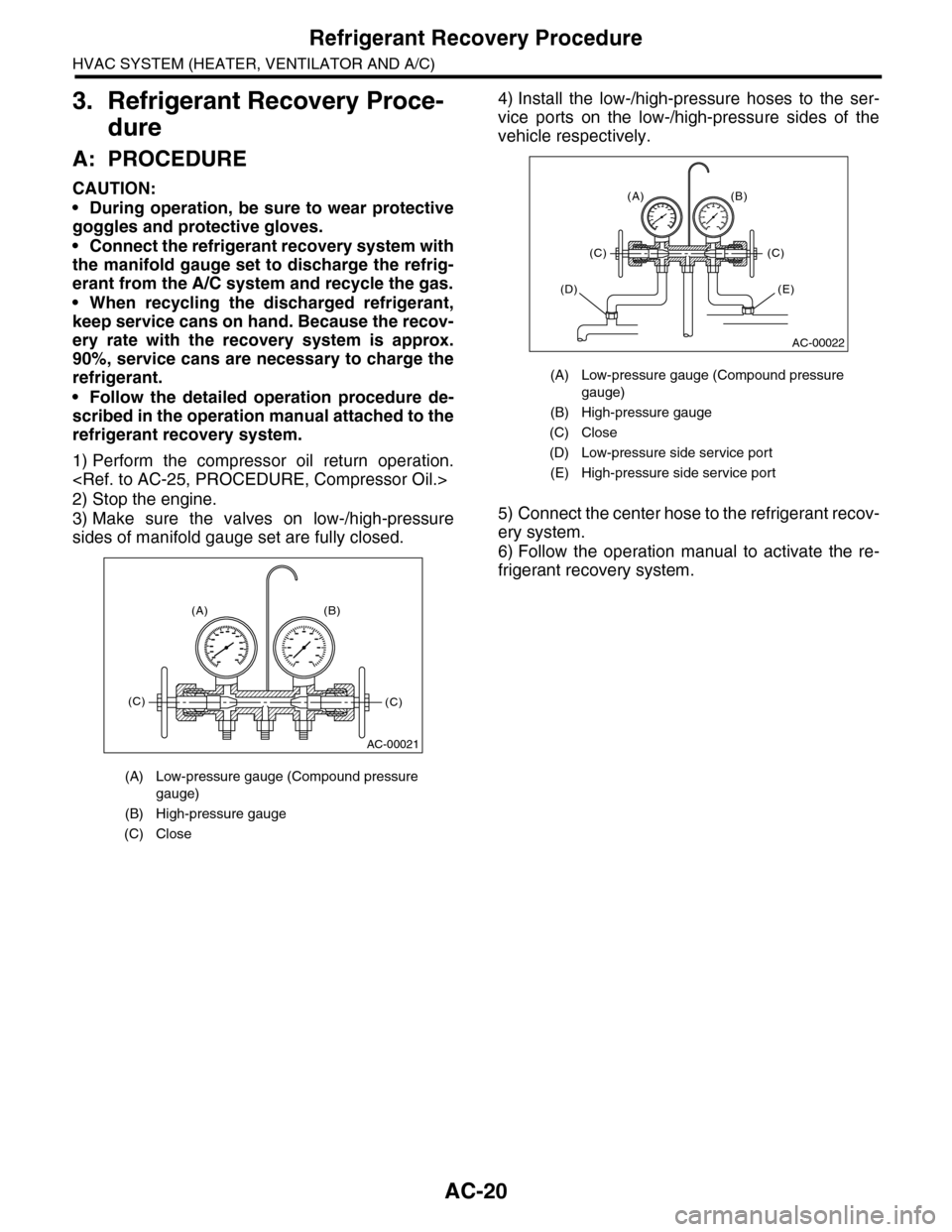
1) Perform the compressor oil return operation.
2) Stop the engine.
3) Make sure the valves on low-/high-pressure
sides of manifold gauge set are fully closed.
4) Install the low-/high-pressure hoses to the ser-
vice ports on the low-/high-pressure sides of the
vehicle respectively.
5) Connect the center hose to the refrigerant recov-
ery system.
6) Follow the operation manual to activate the re-
frigerant recovery system.
(A) Low-pressure gauge (Compound pressure
gauge)
(B) High-pressure gauge
(C) Close
AC-00021
(A) (B)
(C)(C)
(A) Low-pressure gauge (Compound pressure
gauge)
(B) High-pressure gauge
(C) Close
(D) Low-pressure side service port
(E) High-pressure side service port
AC-00022
(A) (B)
(C)(C)
(E)(D)
Page 350 of 2453
AC-24
Refrigerant Leak Check
HVAC SYSTEM (HEATER, VENTILATOR AND A/C)
5. Refrigerant Leak Check
A: INSPECTION
1) At engine speed below 1500rpm, operate the A/
C system for approx. 10 minutes, and confirm that
the high-side pressure shows at least 690 kPa
(7.03 kg/cm2, 100 psi). Then stop the engine to
start the leak test.
2) Starting from the connection between high-pres-
sure pipe and evaporator, check the system for
leaks along the high-pressure side through the
compressor. The following items must be checked
thoroughly.
3) Check the joint and seam between pressure
switch (dual switch) and high-pressure pipe.
4) Check the connections between condenser and
pipes, and welded joints on the condenser.
The leak tester may detect the oil on the condenser
fins as a leak.
5) Check the joint between compressor and hoses.
6) Check the machined area of the compressor and
other joints on the compressor.
7) Check the compressor shaft seal at the area
near the center of compressor clutch pulley.
Some shaft seals show a slight amount of leakage,
about 3 g (0.1 oz) per year. This is not a problem.
8) Starting from the connection between low-pres-
sure pipe and evaporator, check the system for
leakage along the low-pressure side through the
compressor. The following items must be checked
thoroughly.
•Connection between 2 parts
•Connection between pipe and plate
•Connection between pipes
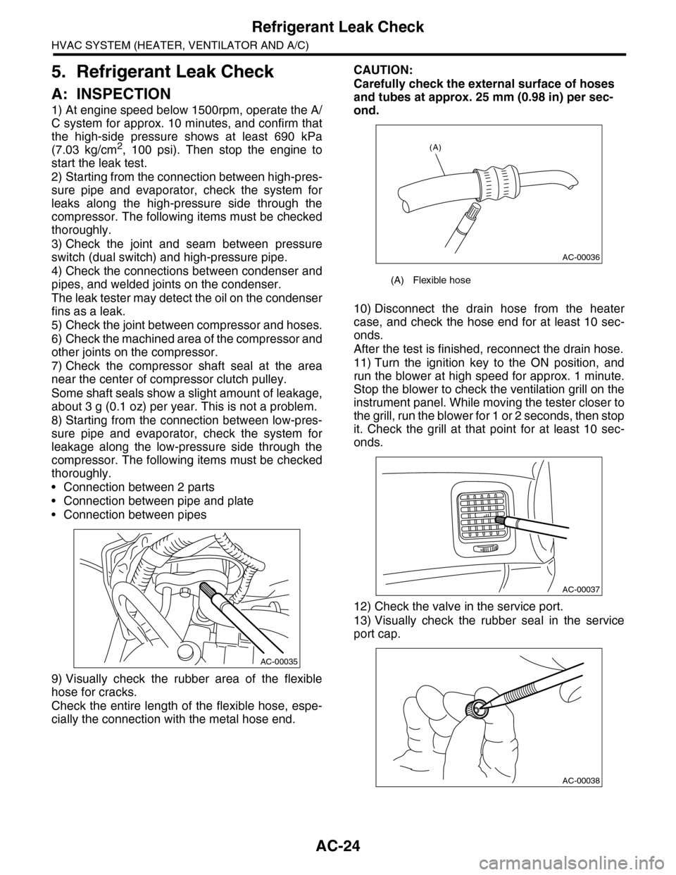
9) Visually check the rubber area of the flexible
hose for cracks.
Check the entire length of the flexible hose, espe-
cially the connection with the metal hose end.
CAUTION:
Carefully check the external surface of hoses
and tubes at approx. 25 mm (0.98 in) per sec-
ond.
10) Disconnect the drain hose from the heater
case, and check the hose end for at least 10 sec-
onds.
After the test is finished, reconnect the drain hose.
11) Turn the ignition key to the ON position, and
run the blower at high speed for approx. 1 minute.
Stop the blower to check the ventilation grill on the
instrument panel. While moving the tester closer to
the grill, run the blower for 1 or 2 seconds, then stop
it. Check the grill at that point for at least 10 sec-
onds.
12) Check the valve in the service port.
13) Visually check the rubber seal in the service
port cap.
AC-00035
(A) Flexible hose
AC-00036
(A)
AC-00037
AC-00038
Page 351 of 2453
AC-25
Compressor Oil
HVAC SYSTEM (HEATER, VENTILATOR AND A/C)
6. Compressor Oil
A: PROCEDURE
NOTE:
Before making repairs, perform the oil return oper-
ation to return the compressor oil in circulation with
the refrigerant to the compressor.
1) Increase the engine to 1,500 rpm.
2) Turn on the A/C switch.
3) Turn the temperature control switch to MAX
COOL.
4) Put in RECIRC position.
5) Turn the blower control switch to HI. (For models
with rear coolers, also turn the rear cooler fan
switch to HI)
6) Leave in this condition for 10 minutes.
B: REPLACEMENT
NOTE:
•If a component has been replaced, add an ap-
propriate amount of compressor oil (same as the
amount of remaining oil in removed component).
•When replacing the compressor, the new com-
pressor will already have the specified amount of
oil in it. Install the new compressor after removing
the same amount of oil that is remaining in the com-
pressor removed.
Page 359 of 2453
AC-33
Compressor
HVAC SYSTEM (HEATER, VENTILATOR AND A/C)
14.Compressor
A: INSPECTION
1. MAGNETIC CLUTCH CLEARANCE
Check the clearance of the entire circumference
around the drive plate and pulley.
Standard:
0.45±0.15 mm (0.0177±0.0059 in)
2. MAGNETIC CLUTCH OPERATION
1) Disconnect the compressor connector.
2) Connect the positive (+) lead from the battery to
the compressor connector terminal, and the nega-
tive (–) lead to the compressor body.
3) Check the magnet clutch engagement.
If there is a problem, replace the compressor.
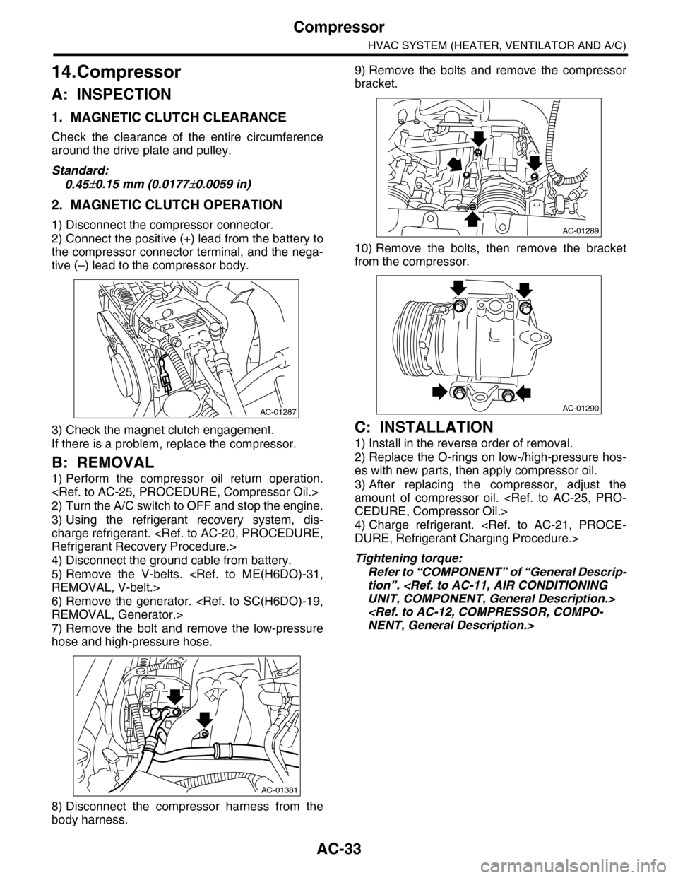
B: REMOVAL
1) Perform the compressor oil return operation.
2) Turn the A/C switch to OFF and stop the engine.
3) Using the refrigerant recovery system, dis-
charge refrigerant.
4) Disconnect the ground cable from battery.
5) Remove the V-belts.
6) Remove the generator.
7) Remove the bolt and remove the low-pressure
hose and high-pressure hose.
8) Disconnect the compressor harness from the
body harness.
9) Remove the bolts and remove the compressor
bracket.
10) Remove the bolts, then remove the bracket
from the compressor.
C: INSTALLATION
1) Install in the reverse order of removal.
2) Replace the O-rings on low-/high-pressure hos-
es with new parts, then apply compressor oil.
3) After replacing the compressor, adjust the
amount of compressor oil.
4) Charge refrigerant.
Tightening torque:
Refer to “COMPONENT” of “General Descrip-
tion”.
AC-01287
AC-01381
AC-01289
AC-01290
Page 441 of 2453
IDI-2
General Description
INSTRUMENTATION/DRIVER INFO
1. General Description
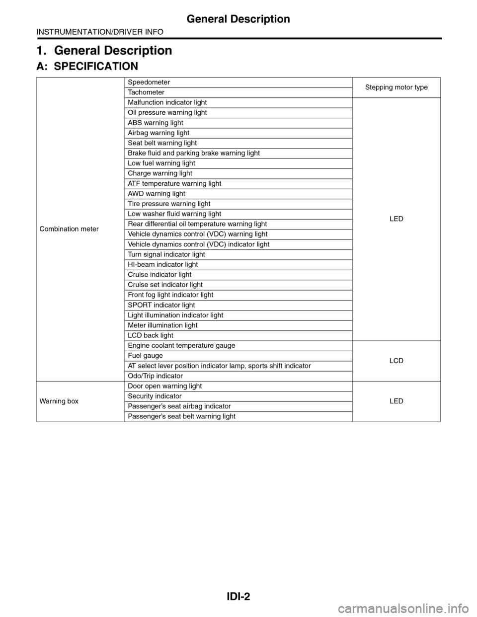
A: SPECIFICATION
Combination meter
SpeedometerStepping motor typeTa c h o m e t e r
Malfunction indicator light
LED
Oil pressure warning light
ABS warning light
Airbag warning light
Seat belt warning light
Brake fluid and parking brake warning light
Low fuel warning light
Charge warning light
AT F t e m p e r a t u r e w a r n i n g l i g h t
AW D war n in g l i gh t
Tire pressure warning light
Low washer fluid warning light
Rear differential oil temperature warning light
Ve h i c l e d y n a m i c s c o n t r o l ( V D C ) w a r n i n g l i g h t
Ve h i c l e d y n a m i c s c o n t r o l ( V D C ) i n d i c a t o r l i g h t
Tu r n s i g n a l i n d i c a t o r l i g h t
HI-beam indicator light
Cruise indicator light
Cruise set indicator light
Fr o nt fog li g ht i nd i ca to r li g ht
SPORT indicator light
Light illumination indicator light
Meter illumination light
LCD back light
Engine coolant temperature gauge
LCDFuel gauge
AT s e l e c t l e v e r p o s i t i o n i n d i c a t o r l a m p , s p o r t s s h i f t i n d i c a t o r
Odo/Trip indicator
Wa r ni n g b ox
Door open warning light
LEDSecurity indicator
Passenger’s seat airbag indicator
Passenger’s seat belt war ning light
Page 757 of 2453
BVC(diag)-2
Basic Diagnostic Procedure
BRAKE VACUUM CONTROL (BVC) (DIAGNOSTICS)
1. Basic Diagnostic Procedure
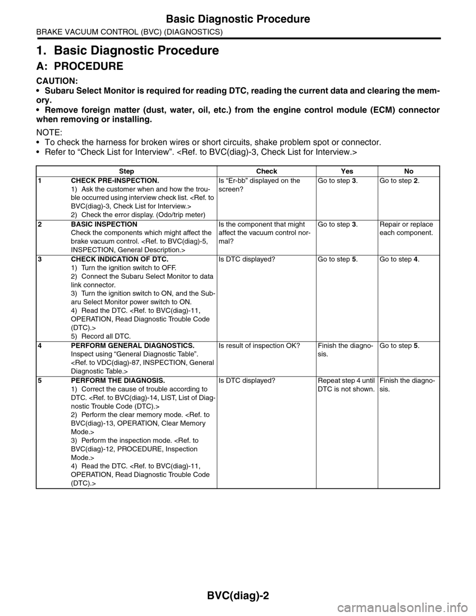
A: PROCEDURE
CAUTION:
•Subaru Select Monitor is required for reading DTC, reading the current data and clearing the mem-
ory.
•Remove foreign matter (dust, water, oil, etc.) from the engine control module (ECM) connector
when removing or installing.
NOTE:
•To check the harness for broken wires or short circuits, shake problem spot or connector.
•Refer to “Check List for Interview”.
Step Check Yes No
1CHECK PRE-INSPECTION.
1) Ask the customer when and how the trou-
ble occurred using interview check list.
2) Check the error display. (Odo/trip meter)
Is “Er-bb” displayed on the
screen?
Go to step 3.Go to step 2.
2BASIC INSPECTION
Check the components which might affect the
brake vacuum control.
Is the component that might
affect the vacuum control nor-
mal?
Go to step 3.Repair or replace
each component.
3CHECK INDICATION OF DTC.
1) Turn the ignition switch to OFF.
2) Connect the Subaru Select Monitor to data
link connector.
3) Turn the ignition switch to ON, and the Sub-
aru Select Monitor power switch to ON.
4) Read the DTC.
(DTC).>
5) Record all DTC.
Is DTC displayed? Go to step 5.Go to step 4.
4PERFORM GENERAL DIAGNOSTICS.
Inspect using “General Diagnostic Table”.
Is result of inspection OK? Finish the diagno-
sis.
Go to step 5.
5PERFORM THE DIAGNOSIS.
1) Correct the cause of trouble according to
DTC.
2) Perform the clear memory mode.
Mode.>
3) Perform the inspection mode.
Mode.>
4) Read the DTC.
(DTC).>
Is DTC displayed? Repeat step 4 until
DTC is not shown.
Finish the diagno-
sis.
Page 818 of 2453
DI-34
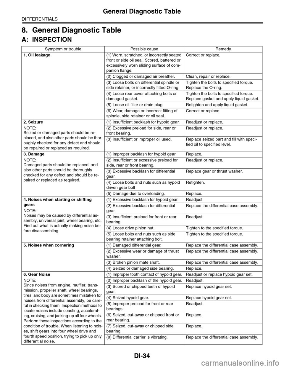
General Diagnostic Table
DIFFERENTIALS
8. General Diagnostic Table
A: INSPECTION
Symptom or trouble Possible cause Remedy
1. Oil leakage(1) Worn, scratched, or incorrectly seated
front or side oil seal. Scored, battered or
excessively wor n sliding surface of com-
panion flange.
Correct or replace.
(2) Clogged or damaged air breather. Clean, repair or replace.
(3) Loose bolts on differential spindle or
side retainer, or incorrectly fitted O-ring.
Tighten the bolts to specified torque.
Replace the O-ring.
(4) Loose rear cover attaching bolts or
damaged gasket.
Tighten the bolts to specified torque.
Replace gasket and apply liquid gasket.
(5) Loose oil filler or drain plug. Retighten and apply liquid gasket.
(6) Wear, damage or incorrect fitting of
spindle, side retainer or oil seal.
Correct or replace.
2. Seizure
NOTE:Seized or damaged parts should be re-
placed, and also other parts should be thor-
oughly checked for any defect and should
be repaired or replaced as required.
(1) Insufficient backlash for hypoid gear. Readjust or replace.
(2) Excessive preload for side, rear or
front bearing.
Readjust or replace.
(3) Insufficient or improper oil used. Replace seized part and fill with speci-
fied oil to specified level.
3. Damage
NOTE:Damaged parts should be replaced, and
also other parts should be thoroughly
checked for any defect and should be re-
paired or replaced as required.
(1) Improper backlash for hypoid gear. Replace.
(2) Insufficient or excessive preload for
side, rear or front bearing.
Readjust or replace.
(3) Excessive backlash for differential
gear.
Replace gear or thrust washer.
(4) Loose bolts and nuts such as hypoid
driven gear bolt
Retighten.
(5) Damage due to overloading. Replace.
4. Noises when starting or shifting
gears
NOTE:
Noises may be caused by differential as-
sembly, universal joint, wheel bearing, etc.
Find out what is actually making noise be-
fore disassembling.
(1) Excessive backlash for hypoid gear. Readjust.
(2) Excessive backlash for differential
gear.
Replace the differential case assembly.
(3) Insufficient preload for front or rear
bearing.
Readjust.
(4) Loose drive pinion nut. Tighten to the specified torque.
(5) Loose bolts and nuts such as side
bearing retainer attaching bolt.
Tighten to the specified torque.
5. Noises when cornering(1) Damaged differential gear. Replace the differential case assembly.
(2) Excessive wear or damage of thrust
washer.
Replace the differential case assembly.
(3) Broken pinion mate shaft. Replace the differential case assembly.
(4) Seized or damaged side bearing. Replace.
6. Gear Noise
NOTE:
Since noises from engine, muffler, trans-
mission, propeller shaft, wheel bearings,
tires, and body are sometimes mistaken for
noises from differential assembly, be care-
ful in checking them. Inspection methods to
locate noises include coasting, accelerat-
ing, cruising, and jacking-up all four wheels.
Perform these inspections according to the
condition of trouble. When listening to nois-
es, shift gears into four wheel drive and
fourth speed position, trying to pick up only
differential noise.
(1) Improper tooth contact of hypoid gear. Readjust or replace hypoid gear set.
(2) Improper backlash of the hypoid gear. Readjust.
(3) Scored or chipped teeth of hypoid
gear.
Replace hypoid gear set.
(4) Seized hypoid gear. Replace hypoid gear set.
(5) Improper preload for front or rear
bearings.
Readjust.
(6) Seized, cut-away or chipped front or
rear bearing.
Replace.
(7) Seized, cut-away or chipped side
bearing.
Replace.
(8) Differential carrier is vibrating. Replace the differential case assembly.
Page 882 of 2453
PS-2
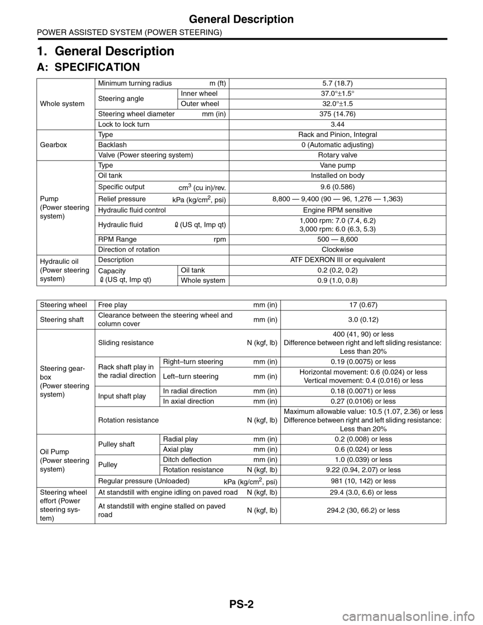
General Description
POWER ASSISTED SYSTEM (POWER STEERING)
1. General Description
A: SPECIFICATION
Whole system
Minimum turning radius m (ft) 5.7 (18.7)
Steering angleInner wheel 37.0°±1.5°
Outer wheel 32.0°±1.5
Steering wheel diameter mm (in) 375 (14.76)
Lock to lock turn 3.44
Gearbox
Ty p e R a c k a n d P i n i o n , I n t e g r a l
Backlash 0 (Automatic adjusting)
Va l ve ( Po w e r s t e e r i n g s y s t e m ) R o t a r y va l ve
Pump
(Power steering
system)
Ty p e Va n e p u m p
Oil tank Installed on body
Specific outputcm3 (cu in)/rev.9.6 (0.586)
Relief pressurekPa (kg/cm2, psi)8,800 — 9,400 (90 — 96, 1,276 — 1,363)
Hydraulic fluid control Engine RPM sensitive
Hydraulic fluid2(US qt, Imp qt)1,000 rpm: 7.0 (7.4, 6.2)
3,000 rpm: 6.0 (6.3, 5.3)
RPM Range rpm 500 — 8,600
Direction of rotation Clockwise
Hydraulic oil
(Power steering
system)
Description ATF DEXRON III or equivalent
Capacity
2(US qt, Imp qt)
Oil tank 0.2 (0.2, 0.2)
Whole system 0.9 (1.0, 0.8)
Steering wheel Free play mm (in) 17 (0.67)
Steering shaftClearance between the steering wheel and
column covermm (in) 3.0 (0.12)
Steering gear-
box
(Power steering
system)
Sliding resistance N (kgf, lb)
400 (41, 90) or less
Difference between right and left sliding resistance:
Less than 20%
Rack shaft play in
the radial direction
Right–turn steering mm (in) 0.19 (0.0075) or less
Left–turn steering mm (in)Horizontal movement: 0.6 (0.024) or less
Ve r t i c a l m o v e m e n t : 0 . 4 ( 0 . 0 1 6 ) o r l e s s
Input shaft playIn radial direction mm (in) 0.18 (0.0071) or less
In axial direction mm (in) 0.27 (0.0106) or less
Rotation resistance N (kgf, lb)
Maximum allowable value: 10.5 (1.07, 2.36) or less
Difference between right and left sliding resistance:
Less than 20%
Oil Pump
(Power steering
system)
Pulley shaftRadial play mm (in) 0.2 (0.008) or less
Axial play mm (in) 0.6 (0.024) or less
PulleyDitch deflection mm (in) 1.0 (0.039) or less
Rotation resistance N (kgf, lb) 9.22 (0.94, 2.07) or less
Regular pressure (Unloaded)kPa (kg/cm2, psi)981 (10, 142) or less
Steering wheel
effort (Power
steering sys-
tem)
At standstill with engine idling on paved road N (kgf, lb) 29.4 (3.0, 6.6) or less
At standstill with engine stalled on paved
roadN (kgf, lb) 294.2 (30, 66.2) or less