brake SUBARU TRIBECA 2009 1.G Service Workshop Manual
[x] Cancel search | Manufacturer: SUBARU, Model Year: 2009, Model line: TRIBECA, Model: SUBARU TRIBECA 2009 1.GPages: 2453, PDF Size: 46.32 MB
Page 2045 of 2453
5AT-29
Road Test
AUTOMATIC TRANSMISSION
4. Road Test
A: INSPECTION
1. GENERAL PRECAUTION
Road tests should be conducted to properly diag-
nose the condition of automatic transmission.
NOTE:
When performing the test, do not exceed posted
speed limit.
2. D RANGE SHIFT FUNCTION
Check shifting between 1st ←→ 2nd ←→ 3rd ←→
4th ←→ 5th while driving on normal city streets.
3. D RANGE SHIFT SHOCK
Check the shock level when shifting up during nor-
mal driving.
4. KICK–DOWN FUNCTION
Check kick–down for each gear. Check the shock
level during kick–down at the same time.
5. ENGINE BRAKE OPERATION
•Check the 4th gear engine brake when shifting
down from 5th to 4th range while driving in 5th gear
of manual mode [50 to 60 km/h (31 to 37 MPH)].
•Check the 3rd gear engine brake when shifting
down from 4th to 3rd range while driving in 4th gear
of manual mode [50 — 60 km/h (31 — 37 MPH)].
•Check the 2nd gear engine brake when shifting
down from 3rd to 2nd range while driving in 3rd
gear of manual mode [40 — 50 km/h (25 — 31
MPH)].
•Check the 1st gear engine brake when shifting
down from 2nd to 1st range while driving in 2nd
gear of manual mode [20 — 30 km/h (12 — 19
MPH)].
6. P RANGE OPERATION
Stop the vehicle on an uphill grade of 5% or more
and shift to the “P” range. Check that the vehicle
does not move when the parking brake is released.
7. NOISE AND VIBRATION
Check for noise and vibration while driving and dur-
ing shifting.
8. OIL LEAKAGE
After the driving test, inspect for oil leaks from the
transmission body.
Page 2046 of 2453
5AT-30
Stall Test
AUTOMATIC TRANSMISSION
5. Stall Test
A: INSPECTION
NOTE:
The stall test is extremely important in diagnosing
the condition of an automatic transmission and en-
gine. It should be conducted to measure the engine
stall speeds in “R” and “2nd of manual mode”.
Purposes of the stall test:
•Operational check of the automatic transmission
clutch
•Operational check of the torque converter clutch
•Engine performance check
1) Check that the throttle valve fully opens.
2) Check that the engine oil level is correct.
3) Check that the coolant level is correct.
4) Check that the ATF level is correct.
5) Check that the differential gear oil level is cor-
rect.
6) Raise the ATF temperature to 70 to 80°C (158 to
176°F) by driving a distance of 5 to 10 km (3 to 6
miles). Confirm the ATF temperature on Subaru
Select Monitor.
tor.>
7) Place the wheel chocks at the front and rear of
all wheels and apply the parking brake.
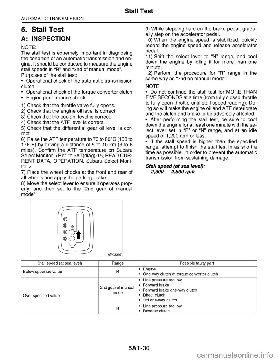
8) Move the select lever to ensure it operates prop-
erly, and then set to the “2nd gear of manual
mode”.
9) While stepping hard on the brake pedal, gradu-
ally step on the accelerator pedal.
10) When the engine speed is stabilized, quickly
record the engine speed and release accelerator
pedal.
11) Shift the select lever to “N” range, and cool
down the engine by idling it for more than one
minute.
12) Perform the procedure for “R” range in the
same way as “2nd on manual mode”.
NOTE:
•Do not continue the stall test for MORE THAN
FIVE SECONDS at a time (from fully closed throttle
to fully open throttle until stall speed reading). Do-
ing so will make the engine oil and ATF deteriorate
and the clutch and brake to be adversely affected.
•After performing the stall test, be sure to cool
down the engine for at least one minute with the se-
lect lever set in “P” or “N” range, and at an idle
speed of 1,200 rpm or less.
•If the stall speed is higher than the specified
range, attempt to finish the stall test in as short a
time as possible, in order to prevent the automatic
transmission from sustaining damage.
Stall speed (at sea level):
2,300 — 2,800 rpm
AT-03297
Stall speed (at sea level) Range Possible faulty part
Below specified value R•Engine
•One-way clutch of torque converter clutch
Over specified value
2nd gear of manual
mode
•Line pressure too low
•Forward brake
•Forward brake one-way clutch
•Direct clutch
•3rd one-way clutch
R•Line pressure too low
•Reverse clutch
Page 2047 of 2453
5AT-31
Time Lag Test
AUTOMATIC TRANSMISSION
6. Time Lag Test
A: INSPECTION
NOTE:
When the select lever is shifted while the engine is
idling, there will be a certain time elapse or lag be-
fore shock is felt. Using this, check the condition of
forward brake, reverse brake, 1st one-way clutch,
forward one-way clutch and 3rd one-way clutch.
•Perform the test at normal operation fluid tem-
perature of 70 — 80°C (158 — 176°F).
•Be sure to allow a one minute interval between
tests.
•Make three measurements and take the average
value.
1) Fully apply the parking brake.
2) Start the engine.
Check the idle speed (A/C OFF).
3) Shift the select lever from “N” to “D” range. Using
a stop watch, measure the time-lag from shifting
the lever until the shock is felt.
Time-lag
Specification: 1.2 sec. or less
If “N” → “D” time-lag is longer than specification:
•Line pressure too low
•Forward brake worn
•One–way clutch not operating properly
4) In the same manner, measure the time lag of “N”
→ “R”.
Time-lag
Specification: 1.5 sec. or less
If “N” → “R” time lag is longer than specification:
•Line pressure too low
•Reverse brake worn
Page 2048 of 2453

5AT-32
Line Pressure Test
AUTOMATIC TRANSMISSION
7. Line Pressure Test
A: MEASUREMENT
NOTE:
If the clutch or brake shows a sign of slippage, or
shifting interval is not correct, check the line pres-
sure.
•Excessive shock during up-shift may be due to
the line pressure being too high.
•Slippage or inability to operate the vehicle may,
in most cases, be due to loss of oil pressure for the
operation of clutch, brake or control valve.
1) Set the vehicle on a lift.
2) Remove the under cover.
3) Remove the test plug and install the ST.
ST 498897200 OIL PRESSURE ADAPTER
4) Set the ST1 and ST2.
ST1 498897200 OIL PRESSURE ADAPTER
ST2 498575400 OIL PRESSURE GAUGE
5) Lower the vehicle, and pull ST1 and ST2 into the
vehicle.
ST1 498897200 OIL PRESSURE ADAPTER
ST2 498575400 OIL PRESSURE GAUGE
6) Connect the Subaru Select Monitor to the data
link connector and read the current data.
TION, Subaru Select Monitor.>
7) Perform the line pressure test.
NOTE:
•Do not perform the line pressure test for more
than 5 seconds at a time. Doing so will make the
engine oil and ATF deteriorate and the clutch and
brake to be adversely affected.
•After performing the line pressure test, be sure to
cool down the engine for at least one minute with
the select lever set in “P” or “N” range and with the
idle speed at 1,200 rpm or less.
•Adjust the throttle valve angle in order to match
the “P/L Solenoid Pressure” displayed on the Sub-
aru Select Monitor.
AT-01752
Range of the
selector lever
Throttle opening
angle
AT F t e m p e r a t u r e
condition
“P/L Solenoid Pressure” dis-
played on the Subaru Select
Monitor
kPa
Standard line pressure
kPa (kg/cm2, psi)
D
Full closed
45 — 55°C
(104 — 131°F)
490385 — 555
(3.93 — 5.66, 55.8 — 80.5)
Full open 1,3701,235 — 1,475
(12.59 — 15.04, 179.1 — 213.9)
RFull closed 1,3701,530 — 1,925
(15.60 — 19.6, 221.9 — 279.2)
Page 2049 of 2453
5AT-33
Transfer Clutch Pressure Test
AUTOMATIC TRANSMISSION
8. Transfer Clutch Pressure
Test
A: INSPECTION
1) Lift-up the vehicle.
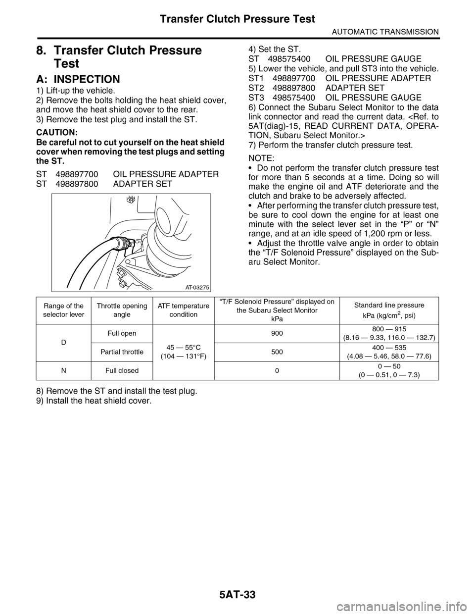
2) Remove the bolts holding the heat shield cover,
and move the heat shield cover to the rear.
3) Remove the test plug and install the ST.
CAUTION:
Be careful not to cut yourself on the heat shield
cover when removing the test plugs and setting
the ST.
ST 498897700 OIL PRESSURE ADAPTER
ST 498897800 ADAPTER SET
4) Set the ST.
ST 498575400 OIL PRESSURE GAUGE
5) Lower the vehicle, and pull ST3 into the vehicle.
ST1 498897700 OIL PRESSURE ADAPTER
ST2 498897800 ADAPTER SET
ST3 498575400 OIL PRESSURE GAUGE
6) Connect the Subaru Select Monitor to the data
link connector and read the current data.
TION, Subaru Select Monitor.>
7) Perform the transfer clutch pressure test.
NOTE:
•Do not perform the transfer clutch pressure test
for more than 5 seconds at a time. Doing so will
make the engine oil and ATF deteriorate and the
clutch and brake to be adversely affected.
•After performing the transfer clutch pressure test,
be sure to cool down the engine for at least one
minute with the select lever set in the “P” or “N”
range, and at an idle speed of 1,200 rpm or less.
•Adjust the throttle valve angle in order to obtain
the “T/F Solenoid Pressure” displayed on the Sub-
aru Select Monitor.
8) Remove the ST and install the test plug.
9) Install the heat shield cover.
AT-03275
Range of the
selector lever
Throttle opening
angle
AT F t e m p e r a t u r e
condition
“T/F Solenoid Pressure” displayed on
the Subaru Select Monitor
kPa
Standard line pressure
kPa (kg/cm2, psi)
D
Full open
45 — 55°C
(104 — 131°F)
900800 — 915
(8.16 — 9.33, 116.0 — 132.7)
Par tial throttle 500400 — 535
(4.08 — 5.46, 58.0 — 77.6)
NFull closed 00 — 50
(0 — 0.51, 0 — 7.3)
Page 2050 of 2453
5AT-34
Automatic Transmission Assembly
AUTOMATIC TRANSMISSION
9. Automatic Transmission As-
sembly
A: REMOVAL
1) Set the vehicle on a lift.
2) Open the front hood and support with the hood
stay.
3) Disconnect the ground cable from battery.
4) Remove the collector cover.
5) Remove the air intake chamber.
6) Remove the air breather hose.
7) Remove the starter.
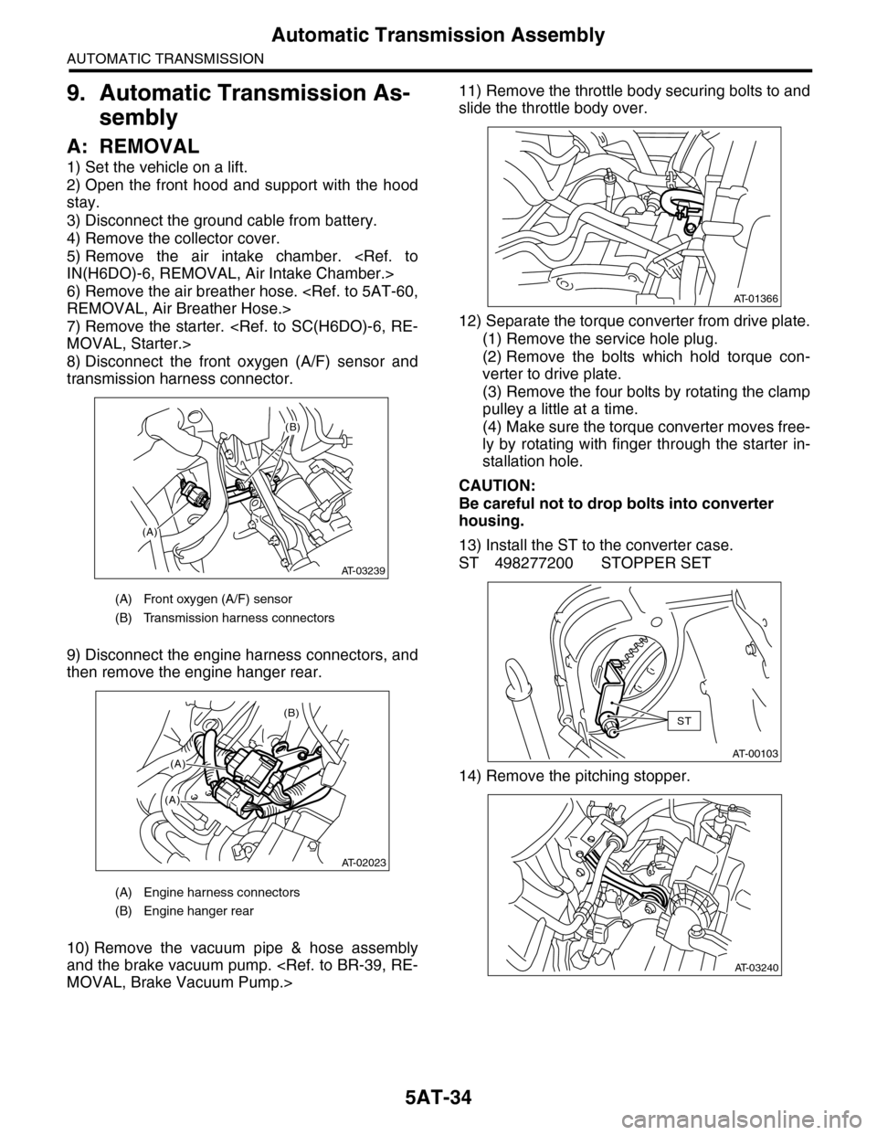
8) Disconnect the front oxygen (A/F) sensor and
transmission harness connector.
9) Disconnect the engine harness connectors, and
then remove the engine hanger rear.
10) Remove the vacuum pipe & hose assembly
and the brake vacuum pump.
11) Remove the throttle body securing bolts to and
slide the throttle body over.
12) Separate the torque converter from drive plate.
(1) Remove the service hole plug.
(2) Remove the bolts which hold torque con-
verter to drive plate.
(3) Remove the four bolts by rotating the clamp
pulley a little at a time.
(4) Make sure the torque converter moves free-
ly by rotating with finger through the starter in-
stallation hole.
CAUTION:
Be careful not to drop bolts into converter
housing.
13) Install the ST to the converter case.
ST 498277200 STOPPER SET
14) Remove the pitching stopper.
(A) Front oxygen (A/F) sensor
(B) Transmission harness connectors
(A) Engine harness connectors
(B) Engine hanger rear
(A)
(B)
AT-03239
(B)
(A)
(A)
AT-02023
AT-01366
AT-00103
ST
AT-03240
Page 2055 of 2453
5AT-39
Automatic Transmission Assembly
AUTOMATIC TRANSMISSION
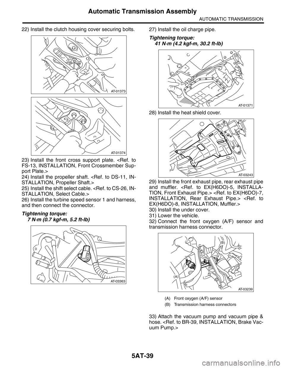
22) Install the clutch housing cover securing bolts.
23) Install the front cross support plate.
port Plate.>
24) Install the propeller shaft.
25) Install the shift select cable.
26) Install the turbine speed sensor 1 and harness,
and then connect the connector.
Tightening torque:
7 N·m (0.7 kgf-m, 5.2 ft-lb)
27) Install the oil charge pipe.
Tightening torque:
41 N·m (4.2 kgf-m, 30.2 ft-lb)
28) Install the heat shield cover.
29) Install the front exhaust pipe, rear exhaust pipe
and muffler.
30) Install the under cover.
31) Lower the vehicle.
32) Connect the front oxygen (A/F) sensor and
transmission harness connector.
33) Attach the vacuum pump and vacuum pipe &
hose.
AT-01373
AT-01374
AT-03363
(A) Front oxygen (A/F) sensor
(B) Transmission harness connectors
AT-01371
AT-03243
(A)
(B)
AT-03239
Page 2093 of 2453
5AT-77
Oil Pump Cover
AUTOMATIC TRANSMISSION
31.Oil Pump Cover
A: REMOVAL
1) Remove the transmission assembly from vehicle
body.
2) Pull out the torque converter assembly.
3) Remove the transmission harness connector
from stay.
4) Remove the oil charge pipe.
5) Remove the ATF filter inlet and outlet pipes.
6) Separate the converter case and transmission
case.
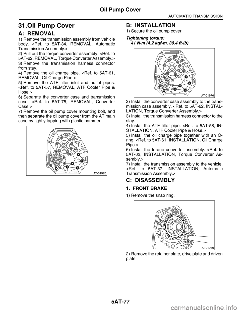
7) Remove the oil pump cover mounting bolt, and
then separate the oil pump cover from the AT main
case by lightly tapping with plastic hammer.
B: INSTALLATION
1) Secure the oil pump cover.
Tightening torque:
41 N·m (4.2 kgf-m, 30.4 ft-lb)
2) Install the converter case assembly to the trans-
mission case assembly.
3) Install the transmission harness connector to the
stay.
4) Install the ATF filter pipe.
5) Install the oil charge pipe together with an O-
ring.
6) Install the torque converter assembly.
sembly.>
7) Install the transmission assembly to the vehicle.
C: DISASSEMBLY
1. FRONT BRAKE
1) Remove the snap ring.
2) Remove the retainer plate, drive plate and driven
plate.
AT-01976
AT-01976
AT-01980
Page 2094 of 2453
5AT-78
Oil Pump Cover
AUTOMATIC TRANSMISSION
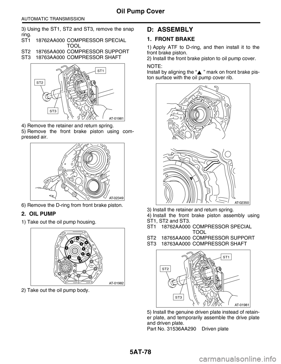
3) Using the ST1, ST2 and ST3, remove the snap
ring.
ST1 18762AA000 COMPRESSOR SPECIAL
TOOL
ST2 18765AA000 COMPRESSOR SUPPORT
ST3 18763AA000 COMPRESSOR SHAFT
4) Remove the retainer and return spring.
5) Remove the front brake piston using com-
pressed air.
6) Remove the D-ring from front brake piston.
2. OIL PUMP
1) Take out the oil pump housing.
2) Take out the oil pump body.
D: ASSEMBLY
1. FRONT BRAKE
1) Apply ATF to D-ring, and then install it to the
front brake piston.
2) Install the front brake piston to oil pump cover.
NOTE:
Install by aligning the “ ” mark on front brake pis-
ton surface with the oil pump cover rib.
3) Install the retainer and return spring.
4) Install the front brake piston assembly using
ST1, ST2 and ST3.
ST1 18762AA000 COMPRESSOR SPECIAL
TOOL
ST2 18765AA000 COMPRESSOR SUPPORT
ST3 18763AA000 COMPRESSOR SHAFT
5) Install the genuine driven plate instead of retain-
er plate, and temporarily assemble the drive plate
and driven plate.
Part No. 31536AA290 Driven plate
AT-01981
ST1
ST2
ST3
AT-02349
AT-01982
AT-02350
AT-01981
ST1
ST2
ST3
Page 2095 of 2453
5AT-79
Oil Pump Cover
AUTOMATIC TRANSMISSION
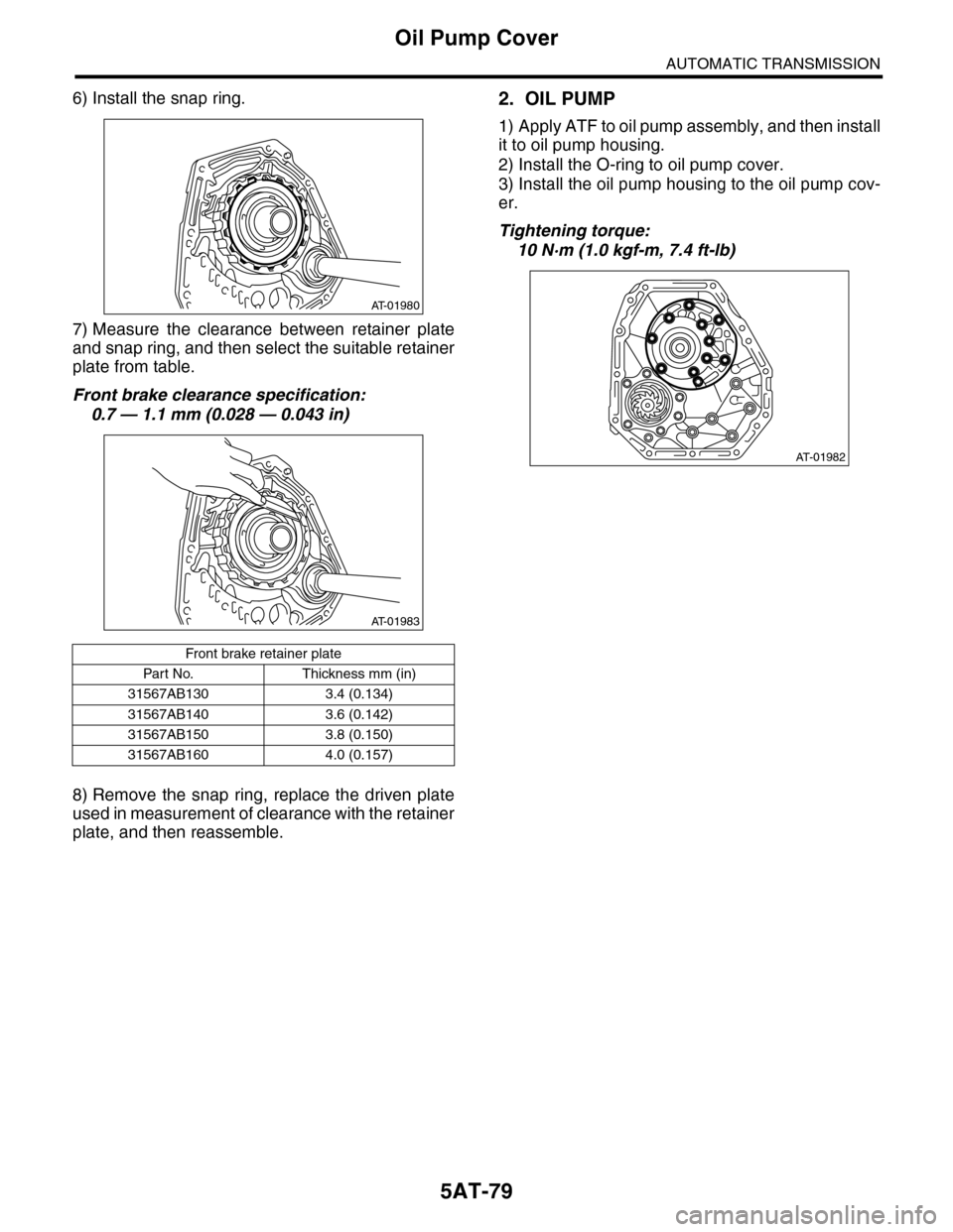
6) Install the snap ring.
7) Measure the clearance between retainer plate
and snap ring, and then select the suitable retainer
plate from table.
Front brake clearance specification:
0.7 — 1.1 mm (0.028 — 0.043 in)
8) Remove the snap ring, replace the driven plate
used in measurement of clearance with the retainer
plate, and then reassemble.
2. OIL PUMP
1) Apply ATF to oil pump assembly, and then install
it to oil pump housing.
2) Install the O-ring to oil pump cover.
3) Install the oil pump housing to the oil pump cov-
er.
Tightening torque:
10 N·m (1.0 kgf-m, 7.4 ft-lb)
Front brake retainer plate
Par t No. Thickness mm (in)
31567AB130 3.4 (0.134)
31567AB140 3.6 (0.142)
31567AB150 3.8 (0.150)
31567AB160 4.0 (0.157)
AT-01980
AT-01983
AT-01982