Rear chain cover SUBARU TRIBECA 2009 1.G Service User Guide
[x] Cancel search | Manufacturer: SUBARU, Model Year: 2009, Model line: TRIBECA, Model: SUBARU TRIBECA 2009 1.GPages: 2453, PDF Size: 46.32 MB
Page 1928 of 2453
ME(H6DO)-62
Cylinder Block
MECHANICAL
21.Cylinder Block
A: REMOVAL
NOTE:
Before conducting this procedure, drain the engine
oil completely.
1) Remove the crank pulley.
2) Remove the front chain cover.
3) Remove the timing chain assembly.
4) Remove the cam sprocket.
5) Remove the crank sprocket.
6) Remove the rear chain cover.
7) Remove the camshaft.
8) Remove the cylinder head.
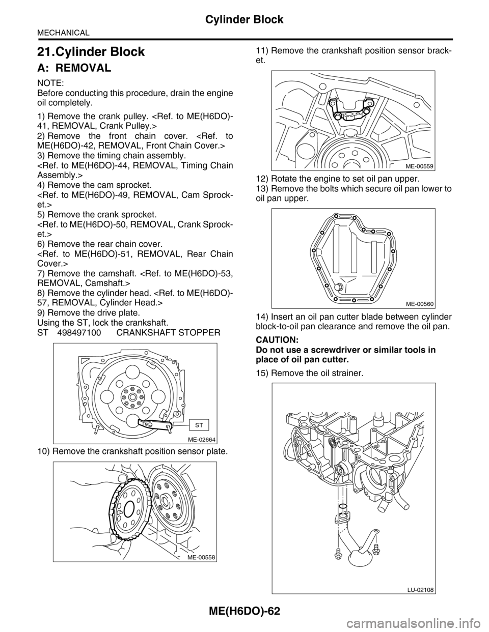
9) Remove the drive plate.
Using the ST, lock the crankshaft.
ST 498497100 CRANKSHAFT STOPPER
10) Remove the crankshaft position sensor plate.
11) Remove the crankshaft position sensor brack-
et.
12) Rotate the engine to set oil pan upper.
13) Remove the bolts which secure oil pan lower to
oil pan upper.
14) Insert an oil pan cutter blade between cylinder
block-to-oil pan clearance and remove the oil pan.
CAUTION:
Do not use a screwdriver or similar tools in
place of oil pan cutter.
15) Remove the oil strainer.
ME-02664
ST
ME-00558
ME-00559
ME-00560
LU-02108
Page 1930 of 2453

ME(H6DO)-64
Cylinder Block
MECHANICAL
B: INSTALLATION
1) After setting the cylinder block to ST, install the
crankshaft bearing.
ST 18232AA000 ENGINE STAND
NOTE:
Remove oil on the mating surface of bearing and
cylinder block before installation. Apply a coat of
engine oil to crankshaft pins.
2) Position the crankshaft and connecting rod on
#2, #4 and #6 cylinder block.
3) Apply liquid gasket to the mating surface of the
#1, #3 and #5 cylinder blocks, and position it on #2,
#4 and #6 cylinder blocks.
Liquid gasket:
THREE BOND 1215 (Part No. 004403007)
NOTE:
Do not allow liquid gasket to run over to O-ring
grooves, oil passages, bearing grooves, etc.
Applying liquid gasket diameter:
1.0±0.2 mm (0.039±0.008 in)
4) Apply a coat of engine oil to the washer and bolt
thread.
5) Tighten all bolts in the numerical order as shown
in the figure.
Tightening torque:
(1) — (11), (13): 25 N·m (2.5 kgf-m, 18 ft-lb)
(12), (14): 20 N·m (2.0 kgf-m, 14 ft-lb)
6) Retighten all bolts in the numerical order as
shown in the figure.
Tightening torque:
(1) — (11), (13): 25 N·m (2.5 kgf-m, 18 ft-lb)
(12), (14): 20 N·m (2.0 kgf-m, 14 ft-lb)
7) Tighten all bolts 90° in the numerical order as
shown in the figure.
8) Install the upper bolt to cylinder block.
Tightening torque:
25 N·m (2.5 kgf-m, 18 ft-lb)
NOTE:
Remove the liquid gasket which is running over to
sealing surface between cylinder block and rear
chain cover, cylinder block and oil pan upper, after
tightening the bolts which combine the cylinder
block.
ME-00567
(1)(6)(8)(3)(9)
(2)(4)(5)(7)(10)
(11)
(12)
(13)
(14)
ME-00568
(1)(6)(8)(3)(9)
(2)(4)(5)(7)(10)
(11)
(12)
(13)
(14)
ME-00568
(1)(6)(8)(3)(9)
(2)(4)(5)(7)(10)
(11)
(12)
(13)
(14)
ME-00568
ME-00569
Page 1934 of 2453
ME(H6DO)-68
Cylinder Block
MECHANICAL
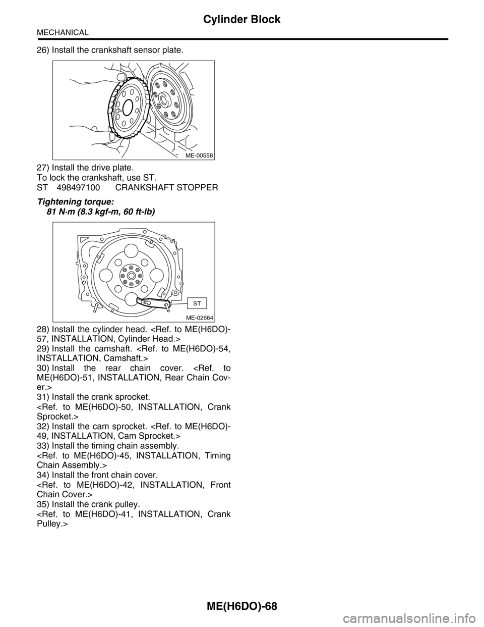
26) Install the crankshaft sensor plate.
27) Install the drive plate.
To lock the crankshaft, use ST.
ST 498497100 CRANKSHAFT STOPPER
Tightening torque:
81 N·m (8.3 kgf-m, 60 ft-lb)
28) Install the cylinder head.
29) Install the camshaft.
30) Install the rear chain cover.
er.>
31) Install the crank sprocket.
32) Install the cam sprocket.
33) Install the timing chain assembly.
34) Install the front chain cover.
35) Install the crank pulley.
ME-00558
ME-02664
ST