ac 25 procedure SUBARU TRIBECA 2009 1.G Service User Guide
[x] Cancel search | Manufacturer: SUBARU, Model Year: 2009, Model line: TRIBECA, Model: SUBARU TRIBECA 2009 1.GPages: 2453, PDF Size: 46.32 MB
Page 102 of 2453
AB(diag)-78
Diagnostic Chart with Trouble Code
AIRBAG SYSTEM (DIAGNOSTICS)
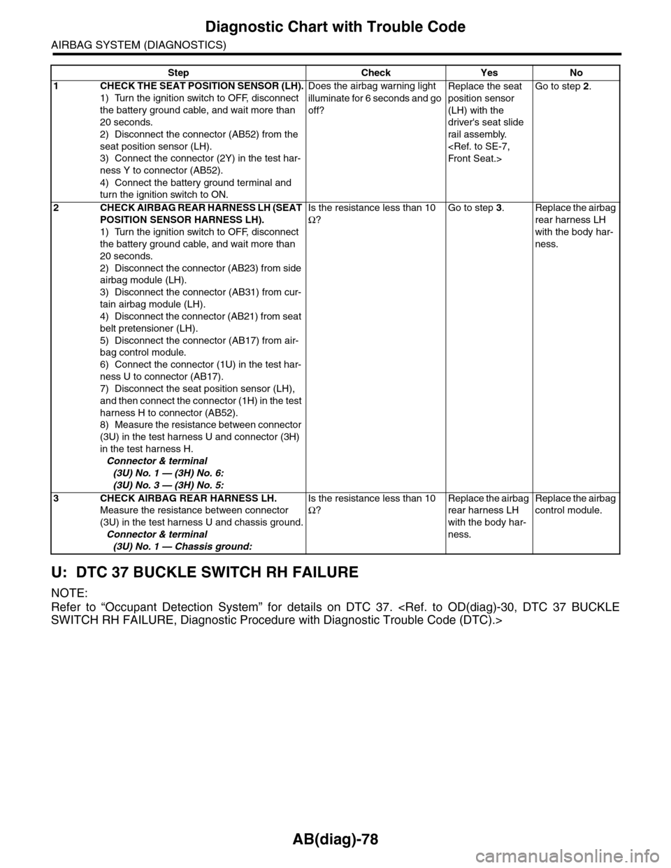
U: DTC 37 BUCKLE SWITCH RH FAILURE
NOTE:
Refer to “Occupant Detection System” for details on DTC 37.
Step Check Yes No
1CHECK THE SEAT POSITION SENSOR (LH).
1) Turn the ignition switch to OFF, disconnect
the battery ground cable, and wait more than
20 seconds.
2) Disconnect the connector (AB52) from the
seat position sensor (LH).
3) Connect the connector (2Y) in the test har-
ness Y to connector (AB52).
4) Connect the battery ground terminal and
turn the ignition switch to ON.
Does the airbag warning light
illuminate for 6 seconds and go
off?
Replace the seat
position sensor
(LH) with the
driver's seat slide
rail assembly.
Go to step 2.
2CHECK AIRBAG REAR HARNESS LH (SEAT
POSITION SENSOR HARNESS LH).
1) Turn the ignition switch to OFF, disconnect
the battery ground cable, and wait more than
20 seconds.
2) Disconnect the connector (AB23) from side
airbag module (LH).
3) Disconnect the connector (AB31) from cur-
tain airbag module (LH).
4) Disconnect the connector (AB21) from seat
belt pretensioner (LH).
5) Disconnect the connector (AB17) from air-
bag control module.
6) Connect the connector (1U) in the test har-
ness U to connector (AB17).
7) Disconnect the seat position sensor (LH),
and then connect the connector (1H) in the test
harness H to connector (AB52).
8) Measure the resistance between connector
(3U) in the test harness U and connector (3H)
in the test harness H.
Connector & terminal
(3U) No. 1 — (3H) No. 6:
(3U) No. 3 — (3H) No. 5:
Is the resistance less than 10
Ω?
Go to step 3.Replace the airbag
rear harness LH
with the body har-
ness.
3CHECK AIRBAG REAR HARNESS LH.
Measure the resistance between connector
(3U) in the test harness U and chassis ground.
Connector & terminal
(3U) No. 1 — Chassis ground:
Is the resistance less than 10
Ω?
Replace the airbag
rear harness LH
with the body har-
ness.
Replace the airbag
control module.
Page 159 of 2453
COM-2
General Description
COMMUNICATION SYSTEM
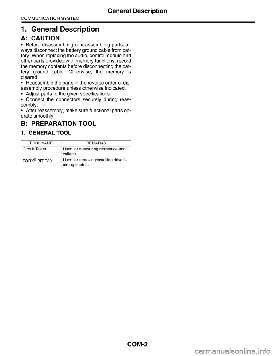
1. General Description
A: CAUTION
•Before disassembling or reassembling parts, al-
ways disconnect the battery ground cable from bat-
tery. When replacing the audio, control module and
other parts provided with memory functions, record
the memory contents before disconnecting the bat-
tery ground cable. Otherwise, the memory is
cleared.
•Reassemble the parts in the reverse order of dis-
assembly procedure unless otherwise indicated.
•Adjust parts to the given specifications.
•Connect the connectors securely during reas-
sembly.
•After reassembly, make sure functional parts op-
erate smoothly.
B: PREPARATION TOOL
1. GENERAL TOOL
TOOL NAME REMARKS
Circuit Tester Used for measuring resistance and
voltage.
TO RX® BIT T30Used for removing/installing driver’s
airbag module.
Page 169 of 2453
CC(ETC)(diag)-2
Basic Diagnostic Procedure
CRUISE CONTROL SYSTEM (DIAGNOSTICS)
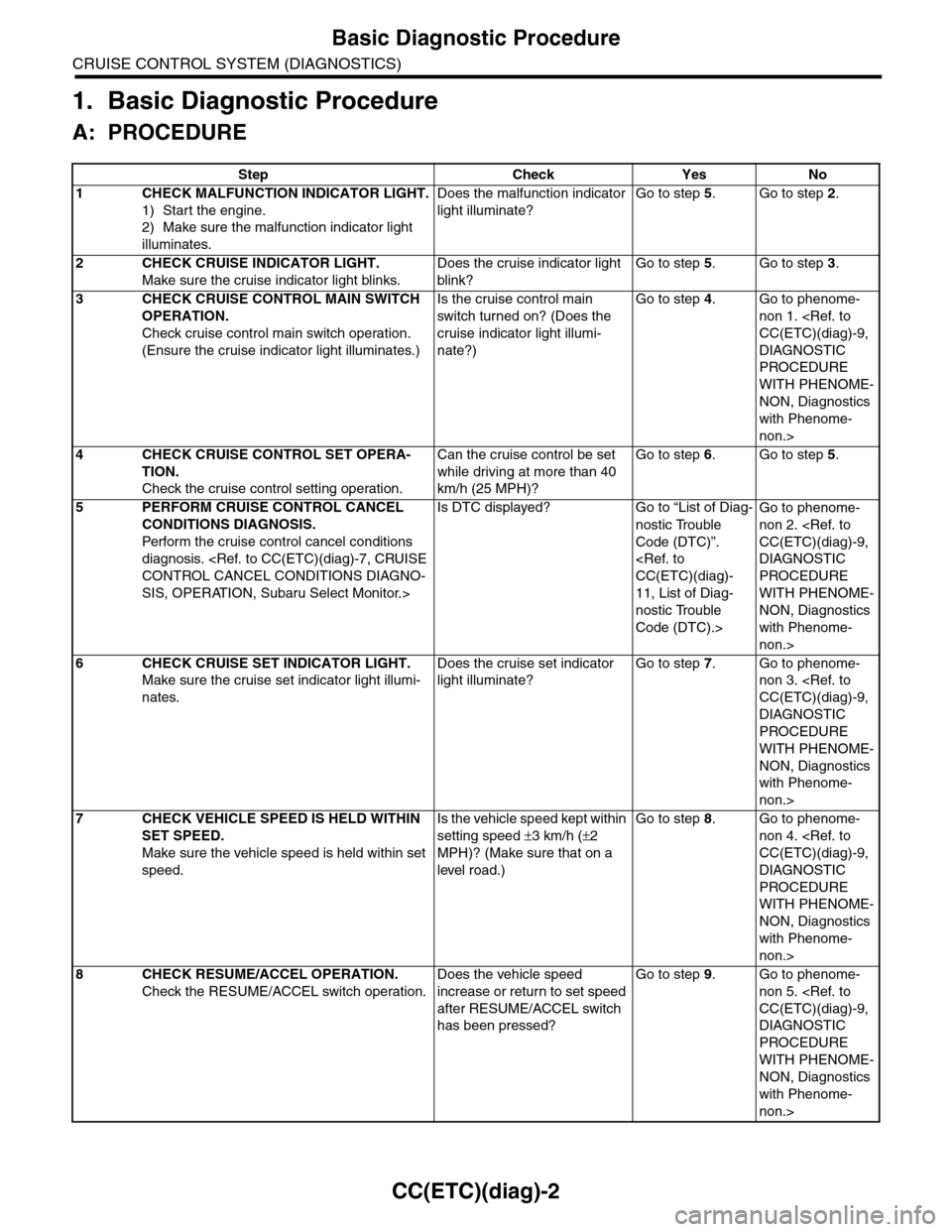
1. Basic Diagnostic Procedure
A: PROCEDURE
Step Check Yes No
1CHECK MALFUNCTION INDICATOR LIGHT.
1) Start the engine.
2) Make sure the malfunction indicator light
illuminates.
Does the malfunction indicator
light illuminate?
Go to step 5.Go to step 2.
2CHECK CRUISE INDICATOR LIGHT.
Make sure the cruise indicator light blinks.
Does the cruise indicator light
blink?
Go to step 5.Go to step 3.
3CHECK CRUISE CONTROL MAIN SWITCH
OPERATION.
Check cruise control main switch operation.
(Ensure the cruise indicator light illuminates.)
Is the cruise control main
switch tur ned on? (Does the
cruise indicator light illumi-
nate?)
Go to step 4.Go to phenome-
non 1.
DIAGNOSTIC
PROCEDURE
WITH PHENOME-
NON, Diagnostics
with Phenome-
non.>
4CHECK CRUISE CONTROL SET OPERA-
TION.
Check the cruise control setting operation.
Can the cruise control be set
while driving at more than 40
km/h (25 MPH)?
Go to step 6.Go to step 5.
5PERFORM CRUISE CONTROL CANCEL
CONDITIONS DIAGNOSIS.
Perfor m the cr uise control cancel conditions
diagnosis.
SIS, OPERATION, Subaru Select Monitor.>
Is DTC displayed? Go to “List of Diag-
nostic Trouble
Code (DTC)”.
11, List of Diag-
nostic Trouble
Code (DTC).>
Go to phenome-
non 2.
DIAGNOSTIC
PROCEDURE
WITH PHENOME-
NON, Diagnostics
with Phenome-
non.>
6CHECK CRUISE SET INDICATOR LIGHT.
Make sure the cruise set indicator light illumi-
nates.
Does the cruise set indicator
light illuminate?
Go to step 7.Go to phenome-
non 3.
DIAGNOSTIC
PROCEDURE
WITH PHENOME-
NON, Diagnostics
with Phenome-
non.>
7CHECK VEHICLE SPEED IS HELD WITHIN
SET SPEED.
Make sure the vehicle speed is held within set
speed.
Is the vehicle speed kept within
setting speed ±3 km/h (±2
MPH)? (Make sure that on a
level road.)
Go to step 8.Go to phenome-
non 4.
DIAGNOSTIC
PROCEDURE
WITH PHENOME-
NON, Diagnostics
with Phenome-
non.>
8CHECK RESUME/ACCEL OPERATION.
Check the RESUME/ACCEL switch operation.
Does the vehicle speed
increase or return to set speed
after RESUME/ACCEL switch
has been pressed?
Go to step 9.Go to phenome-
non 5.
DIAGNOSTIC
PROCEDURE
WITH PHENOME-
NON, Diagnostics
with Phenome-
non.>
Page 170 of 2453
CC(ETC)(diag)-3
Basic Diagnostic Procedure
CRUISE CONTROL SYSTEM (DIAGNOSTICS)
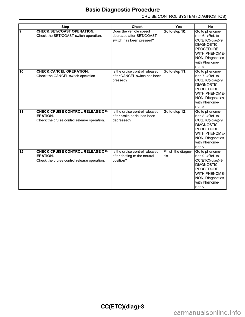
9CHECK SET/COAST OPERATION.
Check the SET/COAST switch operation.
Does the vehicle speed
decrease after SET/COAST
switch has been pressed?
Go to step 10.Go to phenome-
non 6.
DIAGNOSTIC
PROCEDURE
WITH PHENOME-
NON, Diagnostics
with Phenome-
non.>
10 CHECK CANCEL OPERATION.
Check the CANCEL switch operation.
Is the cruise control released
after CANCEL switch has been
pressed?
Go to step 11.Go to phenome-
non 7.
DIAGNOSTIC
PROCEDURE
WITH PHENOME-
NON, Diagnostics
with Phenome-
non.>
11 CHECK CRUISE CONTROL RELEASE OP-
ERATION.
Check the cruise control release operation.
Is the cruise control released
after brake pedal has been
depressed?
Go to step 12.Go to phenome-
non 8.
DIAGNOSTIC
PROCEDURE
WITH PHENOME-
NON, Diagnostics
with Phenome-
non.>
12 CHECK CRUISE CONTROL RELEASE OP-
ERATION.
Check the cruise control release operation.
Is the cruise control released
after shifting to the neutral
position?
Finish the diagno-
sis.
Go to phenome-
non 9.
DIAGNOSTIC
PROCEDURE
WITH PHENOME-
NON, Diagnostics
with Phenome-
non.>
Step Check Yes No
Page 175 of 2453
CC(ETC)(diag)-8
Subaru Select Monitor
CRUISE CONTROL SYSTEM (DIAGNOSTICS)
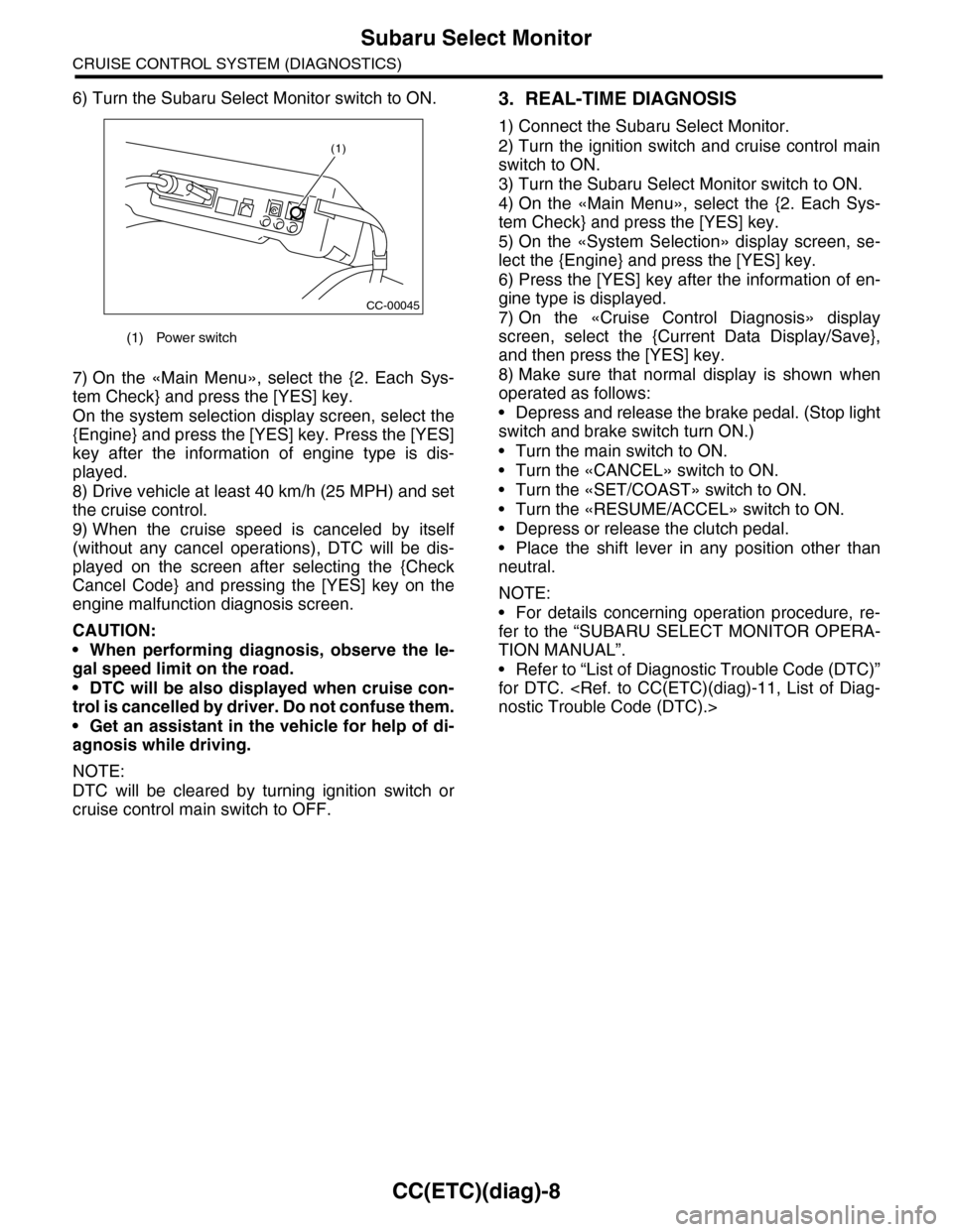
6) Turn the Subaru Select Monitor switch to ON.
7) On the «Main Menu», select the {2. Each Sys-
tem Check} and press the [YES] key.
On the system selection display screen, select the
{Engine} and press the [YES] key. Press the [YES]
key after the information of engine type is dis-
played.
8) Drive vehicle at least 40 km/h (25 MPH) and set
the cruise control.
9) When the cruise speed is canceled by itself
(without any cancel operations), DTC will be dis-
played on the screen after selecting the {Check
Cancel Code} and pressing the [YES] key on the
engine malfunction diagnosis screen.
CAUTION:
•When performing diagnosis, observe the le-
gal speed limit on the road.
•DTC will be also displayed when cruise con-
trol is cancelled by driver. Do not confuse them.
•Get an assistant in the vehicle for help of di-
agnosis while driving.
NOTE:
DTC will be cleared by turning ignition switch or
cruise control main switch to OFF.
3. REAL-TIME DIAGNOSIS
1) Connect the Subaru Select Monitor.
2) Turn the ignition switch and cruise control main
switch to ON.
3) Turn the Subaru Select Monitor switch to ON.
4) On the «Main Menu», select the {2. Each Sys-
tem Check} and press the [YES] key.
5) On the «System Selection» display screen, se-
lect the {Engine} and press the [YES] key.
6) Press the [YES] key after the information of en-
gine type is displayed.
7) On the «Cruise Control Diagnosis» display
screen, select the {Current Data Display/Save},
and then press the [YES] key.
8) Make sure that normal display is shown when
operated as follows:
•Depress and release the brake pedal. (Stop light
switch and brake switch turn ON.)
•Turn the main switch to ON.
•Turn the «CANCEL» switch to ON.
•Turn the «SET/COAST» switch to ON.
•Turn the «RESUME/ACCEL» switch to ON.
•Depress or release the clutch pedal.
•Place the shift lever in any position other than
neutral.
NOTE:
•For details concerning operation procedure, re-
fer to the “SUBARU SELECT MONITOR OPERA-
TION MANUAL”.
•Refer to “List of Diagnostic Trouble Code (DTC)”
for DTC.
(1) Power switch
CC-00045
(1)
Page 176 of 2453
CC(ETC)(diag)-9
Diagnostics with Phenomenon
CRUISE CONTROL SYSTEM (DIAGNOSTICS)
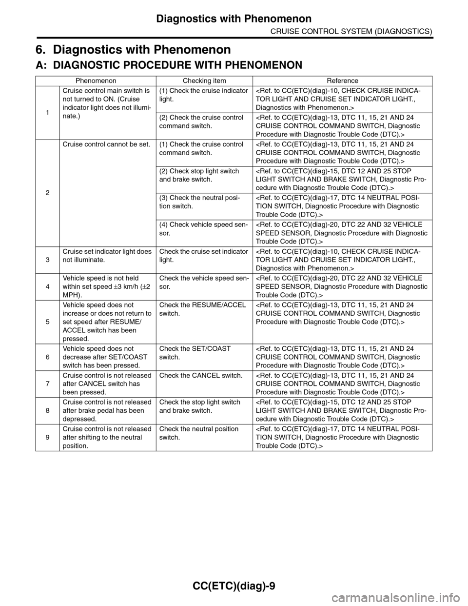
6. Diagnostics with Phenomenon
A: DIAGNOSTIC PROCEDURE WITH PHENOMENON
Phenomenon Checking item Reference
1
Cruise control main switch is
not turned to ON. (Cruise
indicator light does not illumi-
nate.)
(1) Check the cruise indicator
light.
Diagnostics with Phenomenon.>
(2) Check the cruise control
command switch.
Procedure with Diagnostic Trouble Code (DTC).>
2
Cruise control cannot be set. (1) Check the cruise control
command switch.
Procedure with Diagnostic Trouble Code (DTC).>
(2) Check stop light switch
and brake switch.
cedure with Diagnostic Trouble Code (DTC).>
(3) Check the neutral posi-
tion switch.
Tr o u b l e C o d e ( D T C ) . >
(4) Check vehicle speed sen-
sor.
Tr o u b l e C o d e ( D T C ) . >
3
Cruise set indicator light does
not illuminate.
Check the cruise set indicator
light.
Diagnostics with Phenomenon.>
4
Ve h i c l e s p e e d i s n o t h e l d
within set speed ±3 km/h (±2
MPH).
Check the vehicle speed sen-
sor.
Tr o u b l e C o d e ( D T C ) . >
5
Ve h i c l e s p e e d d o e s n o t
increase or does not return to
set speed after RESUME/
ACCEL switch has been
pressed.
Check the RESUME/ACCEL
switch.
Procedure with Diagnostic Trouble Code (DTC).>
6
Ve h i c l e s p e e d d o e s n o t
decrease after SET/COAST
switch has been pressed.
Check the SET/COAST
switch.
Procedure with Diagnostic Trouble Code (DTC).>
7
Cruise control is not released
after CANCEL switch has
been pressed.
Check the CANCEL switch.
Procedure with Diagnostic Trouble Code (DTC).>
8
Cruise control is not released
after brake pedal has been
depressed.
Check the stop light switch
and brake switch.
cedure with Diagnostic Trouble Code (DTC).>
9
Cruise control is not released
after shifting to the neutral
position.
Check the neutral position
switch.
Tr o u b l e C o d e ( D T C ) . >
Page 178 of 2453
CC(ETC)(diag)-11
List of Diagnostic Trouble Code (DTC)
CRUISE CONTROL SYSTEM (DIAGNOSTICS)
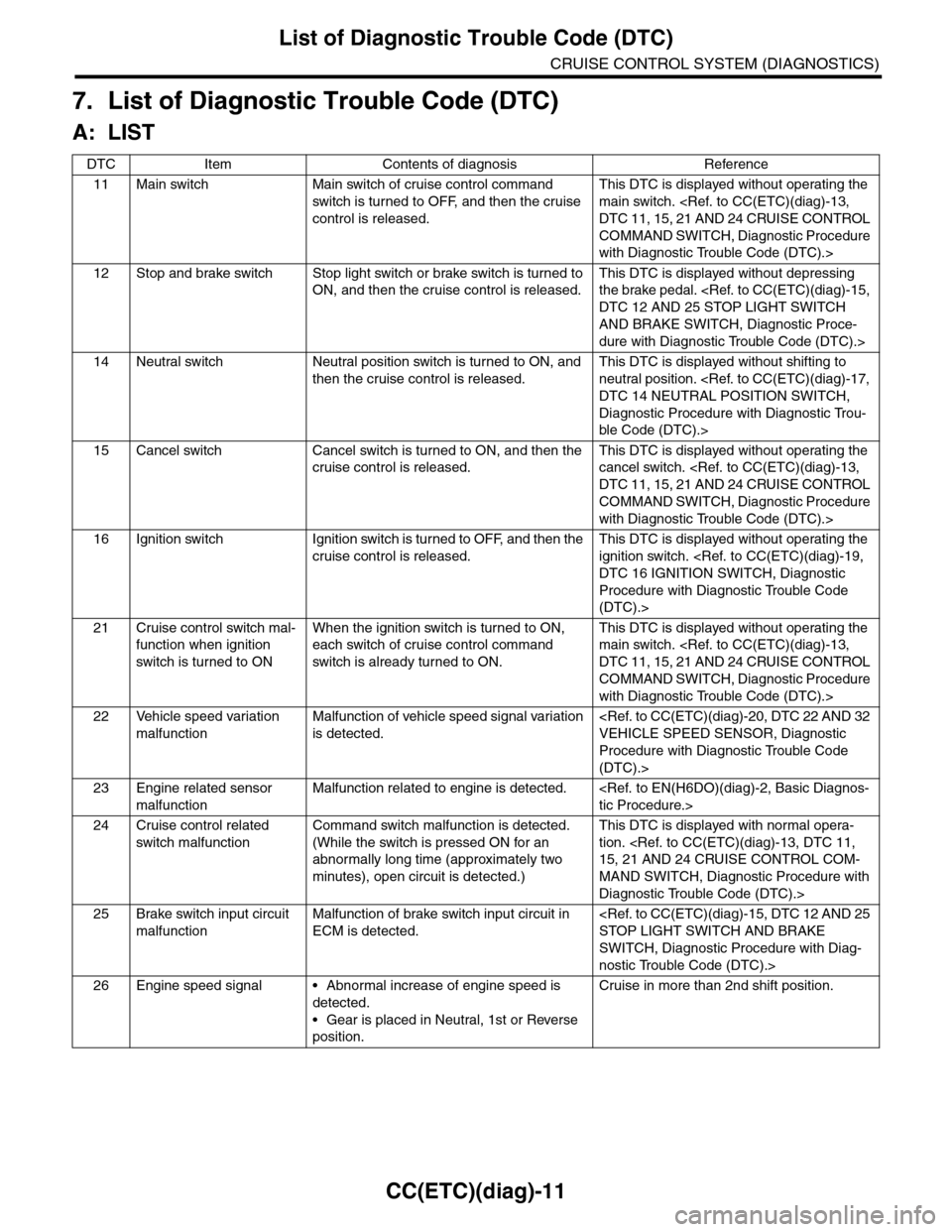
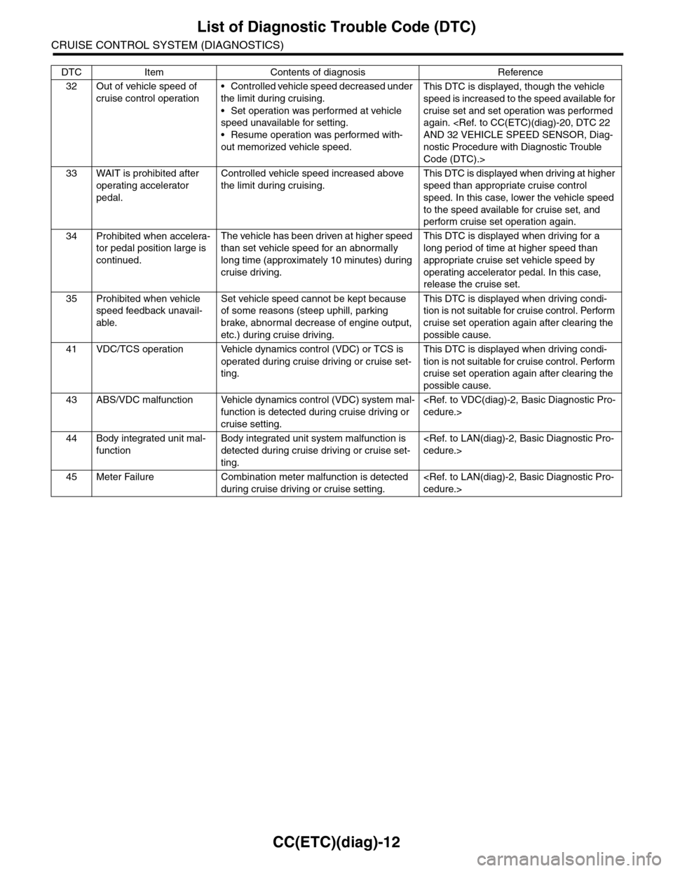
7. List of Diagnostic Trouble Code (DTC)
A: LIST
DTC Item Contents of diagnosis Reference
11 Main switch Main switch of cruise control command
switch is tur ned to OFF, and then the cr uise
control is released.
This DTC is displayed without operating the
main switch.
COMMAND SWITCH, Diagnostic Procedure
with Diagnostic Trouble Code (DTC).>
12 Stop and brake switch Stop light switch or brake switch is turned to
ON, and then the cruise control is released.
This DTC is displayed without depressing
the brake pedal.
AND BRAKE SWITCH, Diagnostic Proce-
dure with Diagnostic Trouble Code (DTC).>
14 Neutral switch Neutral position switch is turned to ON, and
then the cruise control is released.
This DTC is displayed without shifting to
neutral position.
Diagnostic Procedure with Diagnostic Trou-
ble Code (DTC).>
15 Cancel switch Cancel switch is turned to ON, and then the
cruise control is released.
This DTC is displayed without operating the
cancel switch.
COMMAND SWITCH, Diagnostic Procedure
with Diagnostic Trouble Code (DTC).>
16 Ignition switch Ignition switch is turned to OFF, and then the
cruise control is released.
This DTC is displayed without operating the
ignition switch.
Procedure with Diagnostic Trouble Code
(DTC).>
21 Cruise control switch mal-
function when ignition
switch is tur ned to ON
When the ignition switch is turned to ON,
each switch of cruise control command
switch is already tur ned to ON.
This DTC is displayed without operating the
main switch.
COMMAND SWITCH, Diagnostic Procedure
with Diagnostic Trouble Code (DTC).>
22 Vehicle speed variation
malfunction
Malfunction of vehicle speed signal variation
is detected.
Procedure with Diagnostic Trouble Code
(DTC).>
23 Engine related sensor
malfunction
Malfunction related to engine is detected.
24 Cruise control related
switch malfunction
Command switch malfunction is detected.
(While the switch is pressed ON for an
abnormally long time (approximately two
minutes), open circuit is detected.)
This DTC is displayed with normal opera-
tion.
MAND SWITCH, Diagnostic Procedure with
Diagnostic Trouble Code (DTC).>
25 Brake switch input circuit
malfunction
Malfunction of brake switch input circuit in
ECM is detected.
SWITCH, Diagnostic Procedure with Diag-
nostic Trouble Code (DTC).>
26 Engine speed signal • Abnormal increase of engine speed is
detected.
•Gear is placed in Neutral, 1st or Reverse
position.
Cruise in more than 2nd shift position.
Page 179 of 2453
CC(ETC)(diag)-12
List of Diagnostic Trouble Code (DTC)
CRUISE CONTROL SYSTEM (DIAGNOSTICS)
32 Out of vehicle speed of
cruise control operation
•Controlled vehicle speed decreased under
the limit during cruising.
•Set operation was performed at vehicle
speed unavailable for setting.
•Resume operation was performed with-
out memorized vehicle speed.
This DTC is displayed, though the vehicle
speed is increased to the speed available for
cruise set and set operation was performed
again.
nostic Procedure with Diagnostic Trouble
Code (DTC).>
33 WAIT is prohibited after
operating accelerator
pedal.
Controlled vehicle speed increased above
the limit during cruising.
This DTC is displayed when driving at higher
speed than appropriate cruise control
speed. In this case, lower the vehicle speed
to the speed available for cruise set, and
perform cruise set operation again.
34 Prohibited when accelera-
tor pedal position large is
continued.
The vehicle has been driven at higher speed
than set vehicle speed for an abnormally
long time (approximately 10 minutes) during
cruise driving.
This DTC is displayed when driving for a
long period of time at higher speed than
appropriate cruise set vehicle speed by
operating accelerator pedal. In this case,
release the cruise set.
35 Prohibited when vehicle
speed feedback unavail-
able.
Set vehicle speed cannot be kept because
of some reasons (steep uphill, parking
brake, abnormal decrease of engine output,
etc.) during cruise driving.
This DTC is displayed when driving condi-
tion is not suitable for cruise control. Perform
cruise set operation again after clearing the
possible cause.
41 VDC/TCS operation Vehicle dynamics control (VDC) or TCS is
operated during cruise driving or cruise set-
ting.
This DTC is displayed when driving condi-
tion is not suitable for cruise control. Perform
cruise set operation again after clearing the
possible cause.
43 ABS/VDC malfunction Vehicle dynamics control (VDC) system mal-
function is detected during cruise driving or
cruise setting.
44 Body integrated unit mal-
function
Body integrated unit system malfunction is
detected during cruise driving or cruise set-
ting.
45 Meter Failure Combination meter malfunction is detected
during cruise driving or cruise setting.
DTC Item Contents of diagnosis Reference
Page 180 of 2453
CC(ETC)(diag)-13
Diagnostic Procedure with Diagnostic Trouble Code (DTC)
CRUISE CONTROL SYSTEM (DIAGNOSTICS)
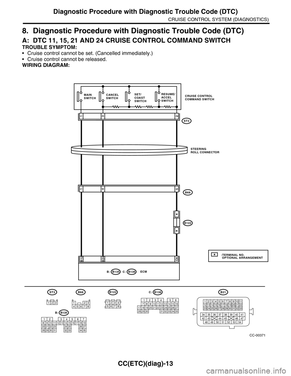
8. Diagnostic Procedure with Diagnostic Trouble Code (DTC)
A: DTC 11, 15, 21 AND 24 CRUISE CONTROL COMMAND SWITCH
TROUBLE SYMPTOM:
•Cruise control cannot be set. (Cancelled immediately.)
•Cruise control cannot be released.
WIRING DIAGRAM:
CC-00371
ST3
SET/COASTSWITCH
RESUME/ACCELSWITCH
CANCELSWITCH
B136C:ECM
B24
2
B68
STEERINGROLL CONNECTOR
31
MAINSWITCH
541
B12C6
*
*
B21
123412131415567816171819910 1120212223 24 25 2627 28 29 3031 32 33
3534 37363938 41404342 4445 47464948 51505352 54
12345678
B68
123
ST3B136
9
302928 3231201918 22211012111424343327261612345613231525871735
C:
* :TERMINAL NO. OPTIONAL ARRANGEMENT
B122
CRUISE CONTROLCOMMAND SWITCH
B135B:
B122
12345678
B135
5672134
29
101112131415252416
30
98171819202821222332312627333435
B:
Page 181 of 2453
CC(ETC)(diag)-14
Diagnostic Procedure with Diagnostic Trouble Code (DTC)
CRUISE CONTROL SYSTEM (DIAGNOSTICS)
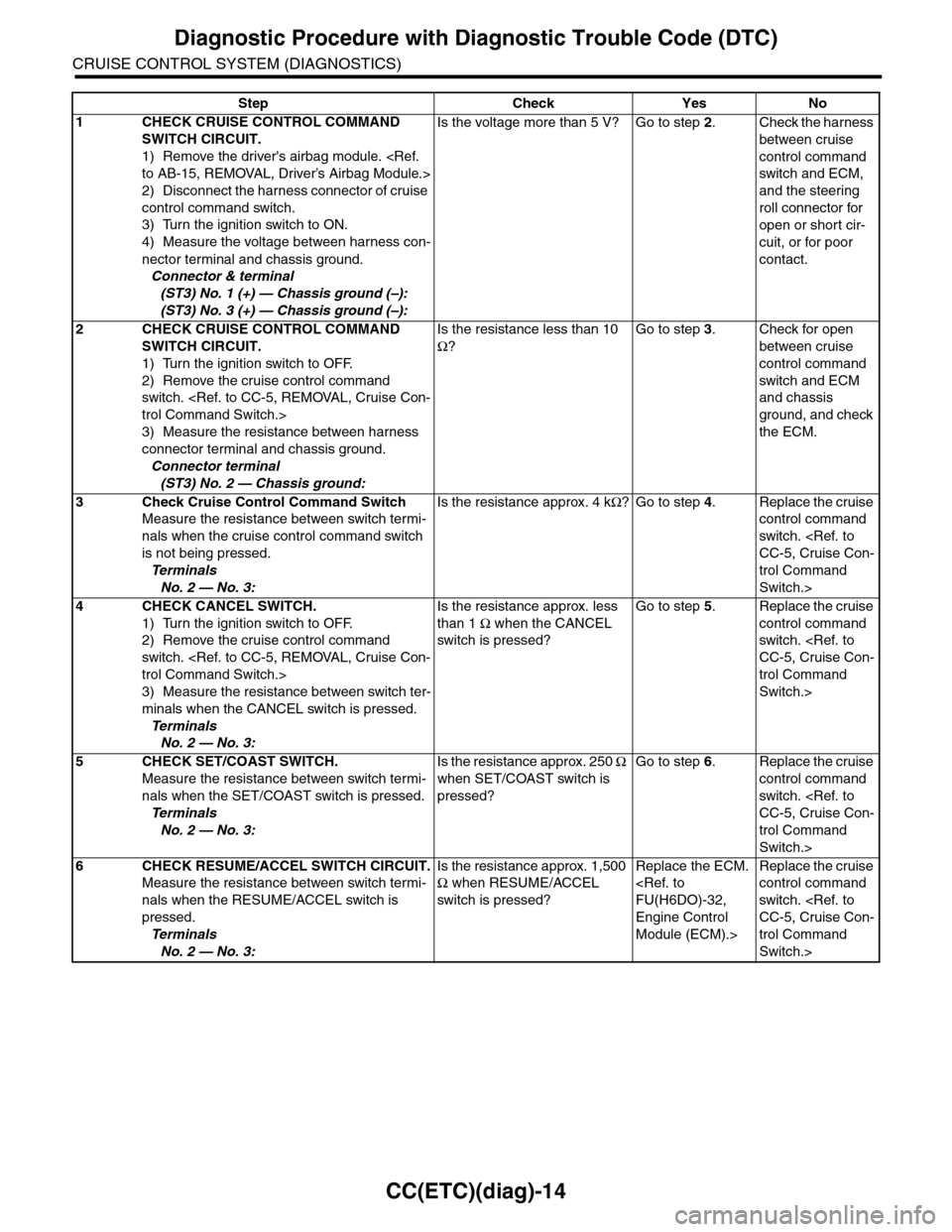
Step Check Yes No
1CHECK CRUISE CONTROL COMMAND
SWITCH CIRCUIT.
1) Remove the driver's airbag module.
2) Disconnect the harness connector of cruise
control command switch.
3) Turn the ignition switch to ON.
4) Measure the voltage between harness con-
nector terminal and chassis ground.
Connector & terminal
(ST3) No. 1 (+) — Chassis ground (–):
(ST3) No. 3 (+) — Chassis ground (–):
Is the voltage more than 5 V? Go to step 2.Check the harness
between cruise
control command
switch and ECM,
and the steering
roll connector for
open or short cir-
cuit, or for poor
contact.
2CHECK CRUISE CONTROL COMMAND
SWITCH CIRCUIT.
1) Turn the ignition switch to OFF.
2) Remove the cruise control command
switch.
3) Measure the resistance between harness
connector terminal and chassis ground.
Connector terminal
(ST3) No. 2 — Chassis ground:
Is the resistance less than 10
Ω?
Go to step 3.Check for open
between cruise
control command
switch and ECM
and chassis
ground, and check
the ECM.
3Check Cruise Control Command Switch
Measure the resistance between switch termi-
nals when the cruise control command switch
is not being pressed.
Te r m i n a l s
No. 2 — No. 3:
Is the resistance approx. 4 kΩ?Go to step 4.Replace the cruise
control command
switch.
trol Command
Switch.>
4CHECK CANCEL SWITCH.
1) Turn the ignition switch to OFF.
2) Remove the cruise control command
switch.
3) Measure the resistance between switch ter-
minals when the CANCEL switch is pressed.
Te r m i n a l s
No. 2 — No. 3:
Is the resistance approx. less
than 1 Ω when the CANCEL
switch is pressed?
Go to step 5.Replace the cruise
control command
switch.
trol Command
Switch.>
5CHECK SET/COAST SWITCH.
Measure the resistance between switch termi-
nals when the SET/COAST switch is pressed.
Te r m i n a l s
No. 2 — No. 3:
Is the resistance approx. 250 Ω
when SET/COAST switch is
pressed?
Go to step 6.Replace the cruise
control command
switch.
trol Command
Switch.>
6CHECK RESUME/ACCEL SWITCH CIRCUIT.
Measure the resistance between switch termi-
nals when the RESUME/ACCEL switch is
pressed.
Te r m i n a l s
No. 2 — No. 3:
Is the resistance approx. 1,500
Ω when RESUME/ACCEL
switch is pressed?
Replace the ECM.
Engine Control
Module (ECM).>
Replace the cruise
control command
switch.
trol Command
Switch.>