ac 25 procedure SUBARU TRIBECA 2009 1.G Service Repair Manual
[x] Cancel search | Manufacturer: SUBARU, Model Year: 2009, Model line: TRIBECA, Model: SUBARU TRIBECA 2009 1.GPages: 2453, PDF Size: 46.32 MB
Page 369 of 2453
AC-43
Ambient Sensor (Auto A/C Model)
HVAC SYSTEM (HEATER, VENTILATOR AND A/C)
22.Ambient Sensor (Auto A/C
Model)
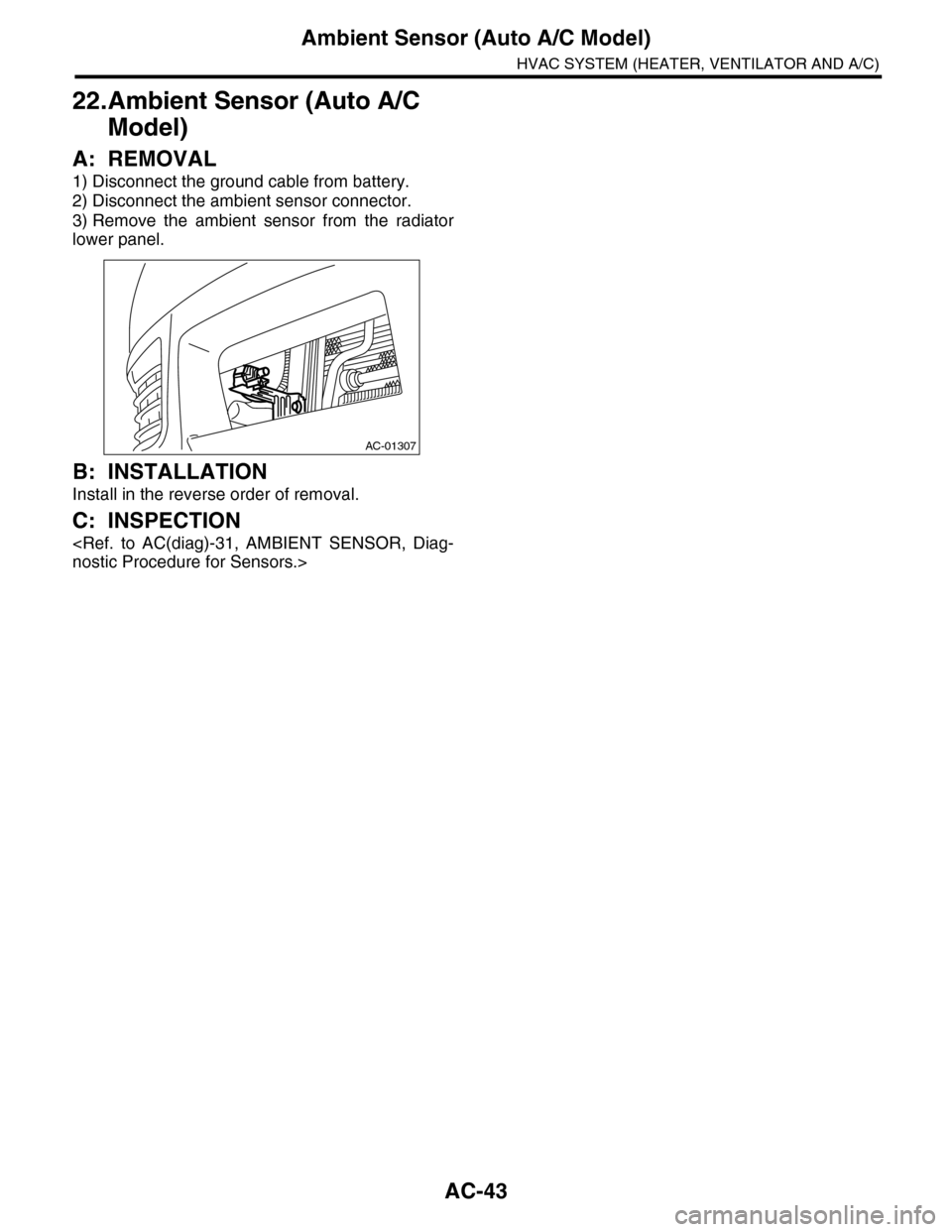
A: REMOVAL
1) Disconnect the ground cable from battery.
2) Disconnect the ambient sensor connector.
3) Remove the ambient sensor from the radiator
lower panel.
B: INSTALLATION
Install in the reverse order of removal.
C: INSPECTION
AC-01307
Page 370 of 2453
AC-44
Sunload Sensor (Auto A/C Model)
HVAC SYSTEM (HEATER, VENTILATOR AND A/C)
23.Sunload Sensor (Auto A/C
Model)
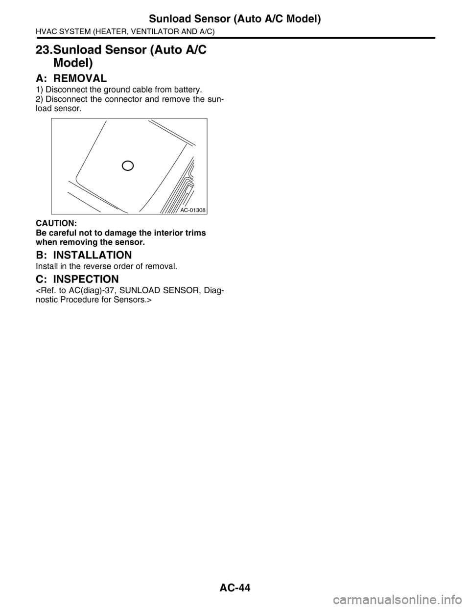
A: REMOVAL
1) Disconnect the ground cable from battery.
2) Disconnect the connector and remove the sun-
load sensor.
CAUTION:
Be careful not to damage the interior trims
when removing the sensor.
B: INSTALLATION
Install in the reverse order of removal.
C: INSPECTION
AC-01308
Page 371 of 2453
AC-45
In-vehicle Sensor (Auto A/C Model)
HVAC SYSTEM (HEATER, VENTILATOR AND A/C)
24.In-vehicle Sensor (Auto A/C
Model)
A: REMOVAL
1) Disconnect the ground cable from battery.
2) Remove the instrument panel lower panel on
driver’s side.
3) Disconnect the connector and aspirator hose,
remove the catch hook and remove the interior
temperature sensor from the knee guard plate.
CAUTION:
Be careful not to damage the sensors and inte-
rior trim when removing.
B: INSTALLATION
Install in the reverse order of removal.
C: INSPECTION
Page 379 of 2453
AC(diag)-2
Basic Diagnostic Procedure
HVAC SYSTEM (AUTO A/C) (DIAGNOSTICS)
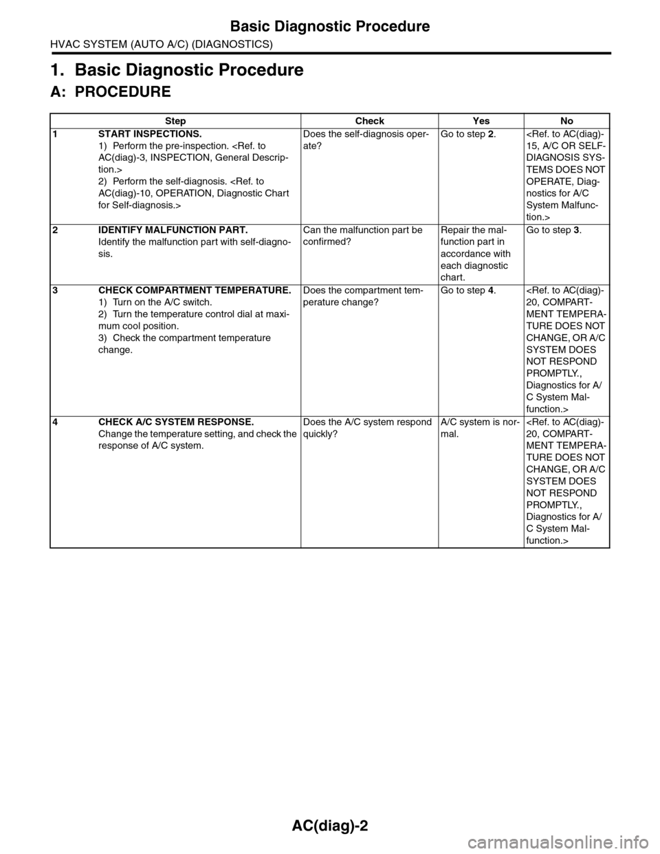
1. Basic Diagnostic Procedure
A: PROCEDURE
Step Check Yes No
1START INSPECTIONS.
1) Perform the pre-inspection.
tion.>
2) Perform the self-diagnosis.
for Self-diagnosis.>
Does the self-diagnosis oper-
ate?
Go to step 2.
DIAGNOSIS SYS-
TEMS DOES NOT
OPERATE, Diag-
nostics for A/C
System Malfunc-
tion.>
2IDENTIFY MALFUNCTION PART.
Identify the malfunction part with self-diagno-
sis.
Can the malfunction part be
confirmed?
Repair the mal-
function part in
accordance with
each diagnostic
chart.
Go to step 3.
3CHECK COMPARTMENT TEMPERATURE.
1) Turn on the A/C switch.
2) Turn the temperature control dial at maxi-
mum cool position.
3) Check the compartment temperature
change.
Does the compartment tem-
perature change?
Go to step 4.
MENT TEMPERA-
TURE DOES NOT
CHANGE, OR A/C
SYSTEM DOES
NOT RESPOND
PROMPTLY.,
Diagnostics for A/
C System Mal-
function.>
4CHECK A/C SYSTEM RESPONSE.
Change the temperature setting, and check the
response of A/C system.
Does the A/C system respond
quickly?
A/C system is nor-
mal.
MENT TEMPERA-
TURE DOES NOT
CHANGE, OR A/C
SYSTEM DOES
NOT RESPOND
PROMPTLY.,
Diagnostics for A/
C System Mal-
function.>
Page 401 of 2453
AC(diag)-24
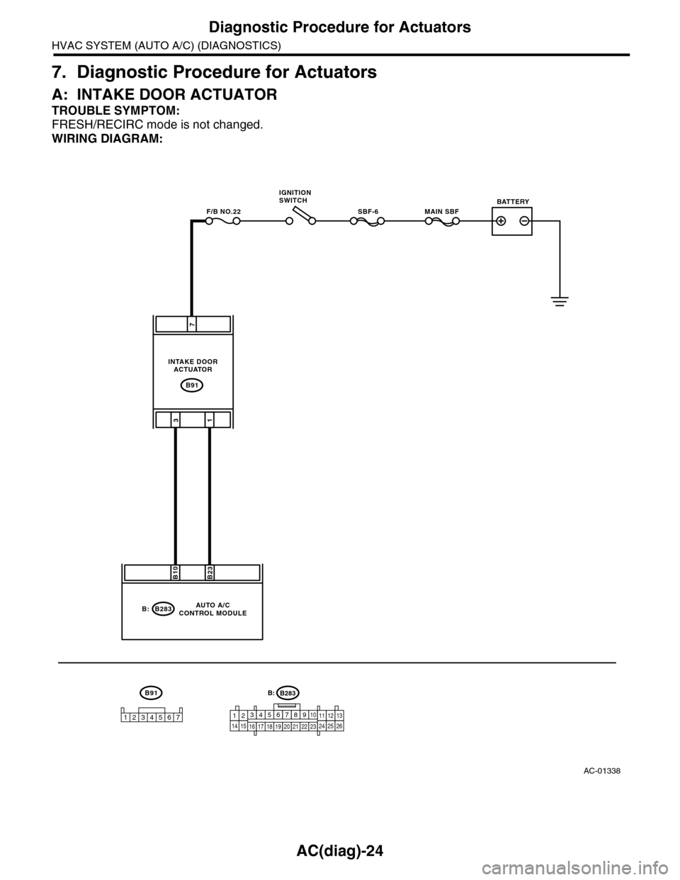
Diagnostic Procedure for Actuators
HVAC SYSTEM (AUTO A/C) (DIAGNOSTICS)
7. Diagnostic Procedure for Actuators
A: INTAKE DOOR ACTUATOR
TROUBLE SYMPTOM:
FRESH/RECIRC mode is not changed.
WIRING DIAGRAM:
AC-01338
B91
MAIN SBFSBF-6F/B NO.22
7
31
B283
B23B10
B:
B91
1234567
AUTO A/CCONTROL MODULE
INTAKE DOORACTUATOR
IGNITIONSWITCHBATTERY
B283B:
1234567891014151617181920212223111213242526
Page 402 of 2453
AC(diag)-25
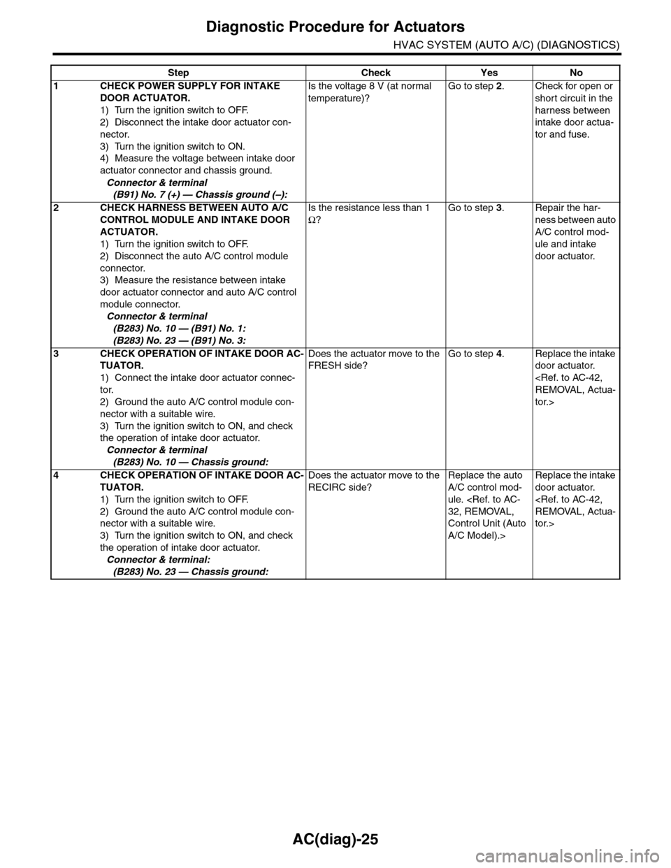
Diagnostic Procedure for Actuators
HVAC SYSTEM (AUTO A/C) (DIAGNOSTICS)
Step Check Yes No
1CHECK POWER SUPPLY FOR INTAKE
DOOR ACTUATOR.
1) Turn the ignition switch to OFF.
2) Disconnect the intake door actuator con-
nector.
3) Turn the ignition switch to ON.
4) Measure the voltage between intake door
actuator connector and chassis ground.
Connector & terminal
(B91) No. 7 (+) — Chassis ground (–):
Is the voltage 8 V (at normal
temperature)?
Go to step 2.Check for open or
short circuit in the
harness between
intake door actua-
tor and fuse.
2CHECK HARNESS BETWEEN AUTO A/C
CONTROL MODULE AND INTAKE DOOR
ACTUATOR.
1) Turn the ignition switch to OFF.
2) Disconnect the auto A/C control module
connector.
3) Measure the resistance between intake
door actuator connector and auto A/C control
module connector.
Connector & terminal
(B283) No. 10 — (B91) No. 1:
(B283) No. 23 — (B91) No. 3:
Is the resistance less than 1
Ω?
Go to step 3.Repair the har-
ness between auto
A/C control mod-
ule and intake
door actuator.
3CHECK OPERATION OF INTAKE DOOR AC-
TUATOR.
1) Connect the intake door actuator connec-
tor.
2) Ground the auto A/C control module con-
nector with a suitable wire.
3) Turn the ignition switch to ON, and check
the operation of intake door actuator.
Connector & terminal
(B283) No. 10 — Chassis ground:
Does the actuator move to the
FRESH side?
Go to step 4.Replace the intake
door actuator.
tor.>
4CHECK OPERATION OF INTAKE DOOR AC-
TUATOR.
1) Turn the ignition switch to OFF.
2) Ground the auto A/C control module con-
nector with a suitable wire.
3) Turn the ignition switch to ON, and check
the operation of intake door actuator.
Connector & terminal:
(B283) No. 23 — Chassis ground:
Does the actuator move to the
RECIRC side?
Replace the auto
A/C control mod-
ule.
Control Unit (Auto
A/C Model).>
Replace the intake
door actuator.
tor.>
Page 403 of 2453
AC(diag)-26
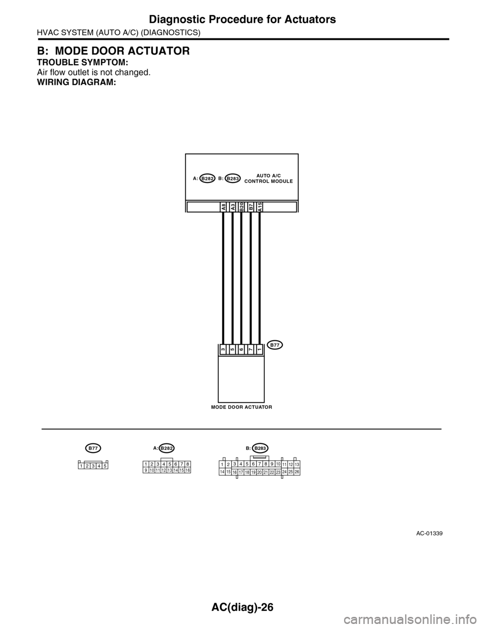
Diagnostic Procedure for Actuators
HVAC SYSTEM (AUTO A/C) (DIAGNOSTICS)
B: MODE DOOR ACTUATOR
TROUBLE SYMPTOM:
Air flow outlet is not changed.
WIRING DIAGRAM:
AC-01339
B77
3412 891011 12 13 14 15 16567
B282A:
B283B282
B77
B20
176
A15B7
B:A:
53
A8A3
12345
MODE DOOR ACTUATOR
AUTO A/CCONTROL MODULE
B283B:
1234567891014151617181920212223111213242526
Page 404 of 2453
AC(diag)-27
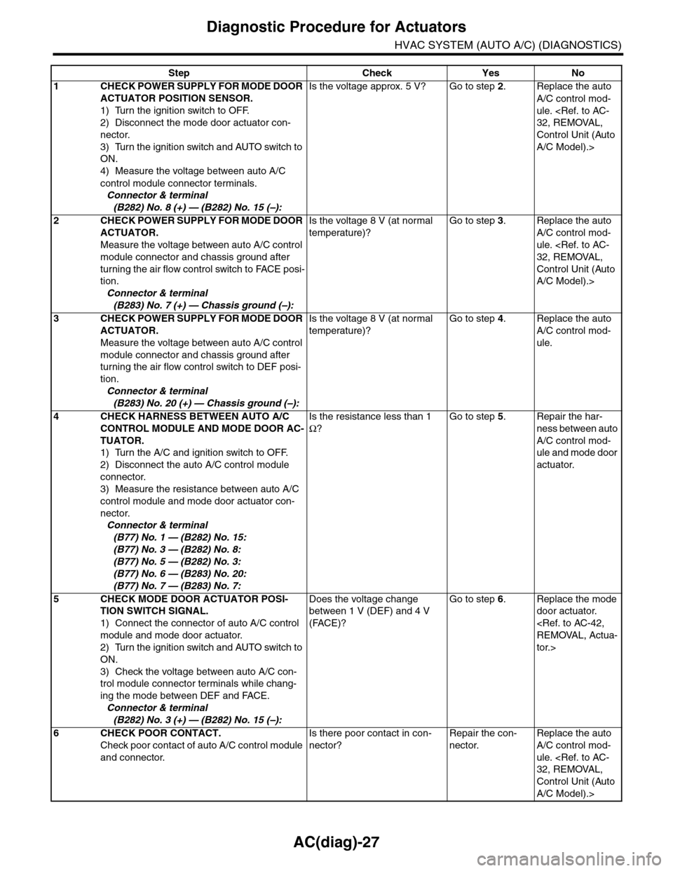
Diagnostic Procedure for Actuators
HVAC SYSTEM (AUTO A/C) (DIAGNOSTICS)
Step Check Yes No
1CHECK POWER SUPPLY FOR MODE DOOR
ACTUATOR POSITION SENSOR.
1) Turn the ignition switch to OFF.
2) Disconnect the mode door actuator con-
nector.
3) Turn the ignition switch and AUTO switch to
ON.
4) Measure the voltage between auto A/C
control module connector terminals.
Connector & terminal
(B282) No. 8 (+) — (B282) No. 15 (–):
Is the voltage approx. 5 V? Go to step 2.Replace the auto
A/C control mod-
ule.
Control Unit (Auto
A/C Model).>
2CHECK POWER SUPPLY FOR MODE DOOR
ACTUATOR.
Measure the voltage between auto A/C control
module connector and chassis ground after
turning the air flow control switch to FACE posi-
tion.
Connector & terminal
(B283) No. 7 (+) — Chassis ground (–):
Is the voltage 8 V (at normal
temperature)?
Go to step 3.Replace the auto
A/C control mod-
ule.
Control Unit (Auto
A/C Model).>
3CHECK POWER SUPPLY FOR MODE DOOR
ACTUATOR.
Measure the voltage between auto A/C control
module connector and chassis ground after
turning the air flow control switch to DEF posi-
tion.
Connector & terminal
(B283) No. 20 (+) — Chassis ground (–):
Is the voltage 8 V (at normal
temperature)?
Go to step 4.Replace the auto
A/C control mod-
ule.
4CHECK HARNESS BETWEEN AUTO A/C
CONTROL MODULE AND MODE DOOR AC-
TUATOR.
1) Turn the A/C and ignition switch to OFF.
2) Disconnect the auto A/C control module
connector.
3) Measure the resistance between auto A/C
control module and mode door actuator con-
nector.
Connector & terminal
(B77) No. 1 — (B282) No. 15:
(B77) No. 3 — (B282) No. 8:
(B77) No. 5 — (B282) No. 3:
(B77) No. 6 — (B283) No. 20:
(B77) No. 7 — (B283) No. 7:
Is the resistance less than 1
Ω?
Go to step 5.Repair the har-
ness between auto
A/C control mod-
ule and mode door
actuator.
5CHECK MODE DOOR ACTUATOR POSI-
TION SWITCH SIGNAL.
1) Connect the connector of auto A/C control
module and mode door actuator.
2) Turn the ignition switch and AUTO switch to
ON.
3) Check the voltage between auto A/C con-
trol module connector terminals while chang-
ing the mode between DEF and FACE.
Connector & terminal
(B282) No. 3 (+) — (B282) No. 15 (–):
Does the voltage change
between 1 V (DEF) and 4 V
(FACE)?
Go to step 6.Replace the mode
door actuator.
tor.>
6CHECK POOR CONTACT.
Check poor contact of auto A/C control module
and connector.
Is there poor contact in con-
nector?
Repair the con-
nector.
Replace the auto
A/C control mod-
ule.
Control Unit (Auto
A/C Model).>
Page 405 of 2453
AC(diag)-28
Diagnostic Procedure for Actuators
HVAC SYSTEM (AUTO A/C) (DIAGNOSTICS)
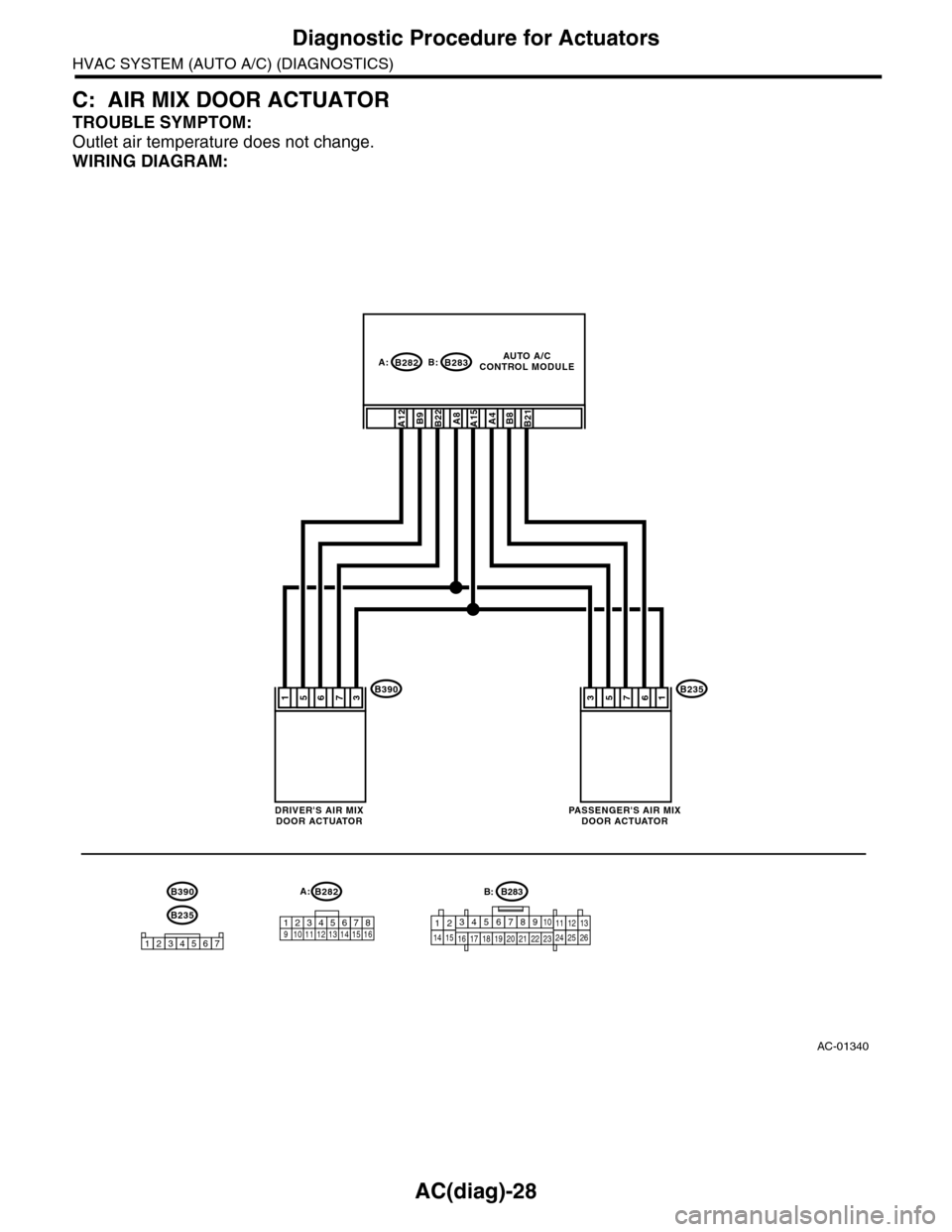
C: AIR MIX DOOR ACTUATOR
TROUBLE SYMPTOM:
Outlet air temperature does not change.
WIRING DIAGRAM:
AC-01340
B2353412 891011 12 13 14 15 16567
B282A:
B283B282
B23567
B:A:
51
1345726
AUTO A/CCONTROL MODULE
PA S S E N G E R ' S A I R M I XDOOR ACTUATOR
B3907653
DRIVER'S AIR MIXDOOR ACTUATOR
B390
A15B8A4B22A8B9A12B21
B283B:
1234567891014151617181920212223111213242526
13
Page 406 of 2453
AC(diag)-29
Diagnostic Procedure for Actuators
HVAC SYSTEM (AUTO A/C) (DIAGNOSTICS)
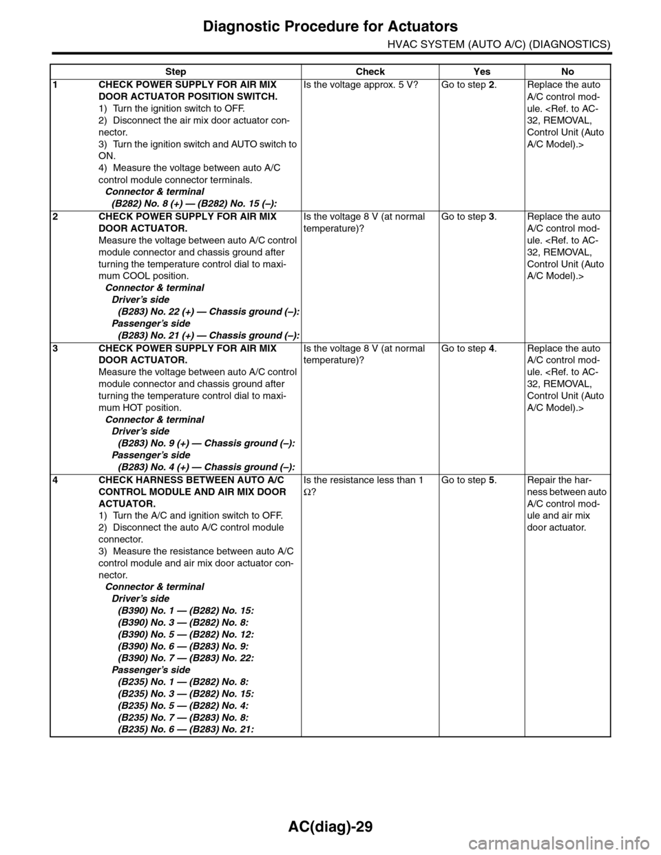
Step Check Yes No
1CHECK POWER SUPPLY FOR AIR MIX
DOOR ACTUATOR POSITION SWITCH.
1) Turn the ignition switch to OFF.
2) Disconnect the air mix door actuator con-
nector.
3) Turn the ignition switch and AUTO switch to
ON.
4) Measure the voltage between auto A/C
control module connector terminals.
Connector & terminal
(B282) No. 8 (+) — (B282) No. 15 (–):
Is the voltage approx. 5 V? Go to step 2.Replace the auto
A/C control mod-
ule.
Control Unit (Auto
A/C Model).>
2CHECK POWER SUPPLY FOR AIR MIX
DOOR ACTUATOR.
Measure the voltage between auto A/C control
module connector and chassis ground after
turning the temperature control dial to maxi-
mum COOL position.
Connector & terminal
Driver’s side
(B283) No. 22 (+) — Chassis ground (–):
Passenger’s side
(B283) No. 21 (+) — Chassis ground (–):
Is the voltage 8 V (at normal
temperature)?
Go to step 3.Replace the auto
A/C control mod-
ule.
Control Unit (Auto
A/C Model).>
3CHECK POWER SUPPLY FOR AIR MIX
DOOR ACTUATOR.
Measure the voltage between auto A/C control
module connector and chassis ground after
turning the temperature control dial to maxi-
mum HOT position.
Connector & terminal
Driver’s side
(B283) No. 9 (+) — Chassis ground (–):
Passenger’s side
(B283) No. 4 (+) — Chassis ground (–):
Is the voltage 8 V (at normal
temperature)?
Go to step 4.Replace the auto
A/C control mod-
ule.
Control Unit (Auto
A/C Model).>
4CHECK HARNESS BETWEEN AUTO A/C
CONTROL MODULE AND AIR MIX DOOR
ACTUATOR.
1) Turn the A/C and ignition switch to OFF.
2) Disconnect the auto A/C control module
connector.
3) Measure the resistance between auto A/C
control module and air mix door actuator con-
nector.
Connector & terminal
Driver’s side
(B390) No. 1 — (B282) No. 15:
(B390) No. 3 — (B282) No. 8:
(B390) No. 5 — (B282) No. 12:
(B390) No. 6 — (B283) No. 9:
(B390) No. 7 — (B283) No. 22:
Passenger’s side
(B235) No. 1 — (B282) No. 8:
(B235) No. 3 — (B282) No. 15:
(B235) No. 5 — (B282) No. 4:
(B235) No. 7 — (B283) No. 8:
(B235) No. 6 — (B283) No. 21:
Is the resistance less than 1
Ω?
Go to step 5.Repair the har-
ness between auto
A/C control mod-
ule and air mix
door actuator.