ac 25 procedure SUBARU TRIBECA 2009 1.G Service Owner's Manual
[x] Cancel search | Manufacturer: SUBARU, Model Year: 2009, Model line: TRIBECA, Model: SUBARU TRIBECA 2009 1.GPages: 2453, PDF Size: 46.32 MB
Page 182 of 2453
CC(ETC)(diag)-15
Diagnostic Procedure with Diagnostic Trouble Code (DTC)
CRUISE CONTROL SYSTEM (DIAGNOSTICS)
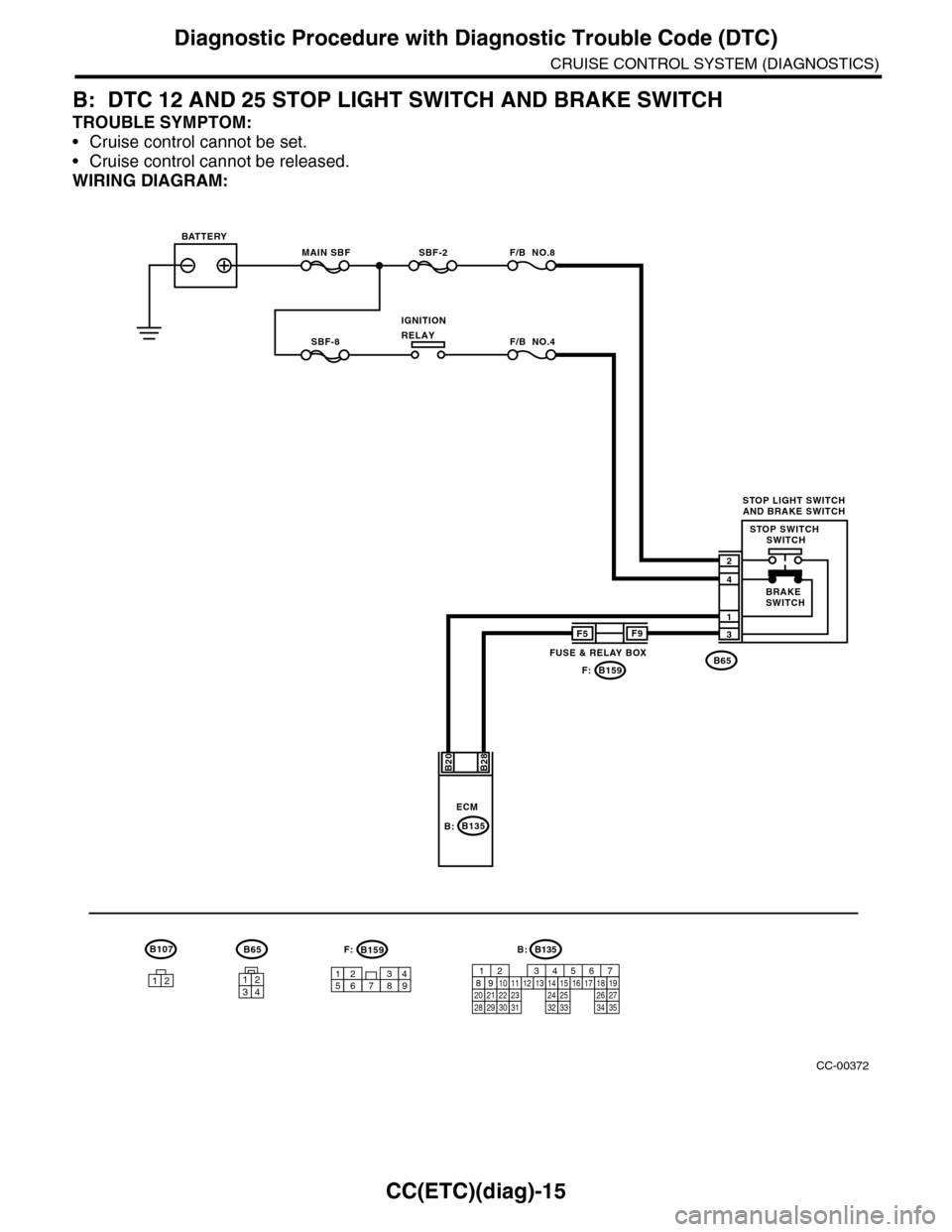
B: DTC 12 AND 25 STOP LIGHT SWITCH AND BRAKE SWITCH
TROUBLE SYMPTOM:
•Cruise control cannot be set.
•Cruise control cannot be released.
WIRING DIAGRAM:
CC-00372
B65
MAIN SBFSBF-2 F/B NO.8
B65
4
3
1
2
B28B20
1234
SBF-8 F/B NO.4
F5
B159
F9
F:
947621538
B159F:
ECM
BATTERY
STOP LIGHT SWITCHAND BRAKE SWITCH
BRAKESWITCH
STOP SWITCH SWITCH
IGNITIONRELAY
FUSE & RELAY BOX
12
B107
B135B:
B135
5672134
29
101112131415252416
30
98171819202821222332312627333435
B:
Page 183 of 2453
CC(ETC)(diag)-16
Diagnostic Procedure with Diagnostic Trouble Code (DTC)
CRUISE CONTROL SYSTEM (DIAGNOSTICS)
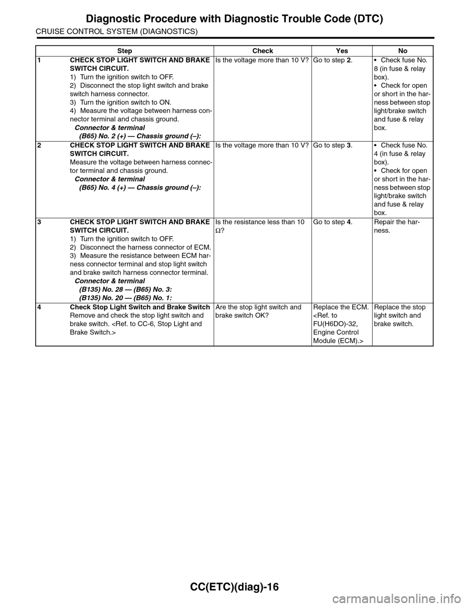
Step Check Yes No
1CHECK STOP LIGHT SWITCH AND BRAKE
SWITCH CIRCUIT.
1) Turn the ignition switch to OFF.
2) Disconnect the stop light switch and brake
switch harness connector.
3) Turn the ignition switch to ON.
4) Measure the voltage between harness con-
nector terminal and chassis ground.
Connector & terminal
(B65) No. 2 (+) — Chassis ground (–):
Is the voltage more than 10 V? Go to step 2.•Check fuse No.
8 (in fuse & relay
box).
•Check for open
or short in the har-
ness between stop
light/brake switch
and fuse & relay
box.
2CHECK STOP LIGHT SWITCH AND BRAKE
SWITCH CIRCUIT.
Measure the voltage between harness connec-
tor terminal and chassis ground.
Connector & terminal
(B65) No. 4 (+) — Chassis ground (–):
Is the voltage more than 10 V? Go to step 3.•Check fuse No.
4 (in fuse & relay
box).
•Check for open
or short in the har-
ness between stop
light/brake switch
and fuse & relay
box.
3CHECK STOP LIGHT SWITCH AND BRAKE
SWITCH CIRCUIT.
1) Turn the ignition switch to OFF.
2) Disconnect the harness connector of ECM.
3) Measure the resistance between ECM har-
ness connector terminal and stop light switch
and brake switch harness connector terminal.
Connector & terminal
(B135) No. 28 — (B65) No. 3:
(B135) No. 20 — (B65) No. 1:
Is the resistance less than 10
Ω?
Go to step 4.Repair the har-
ness.
4Check Stop Light Switch and Brake Switch
Remove and check the stop light switch and
brake switch.
Are the stop light switch and
brake switch OK?
Replace the ECM.
Engine Control
Module (ECM).>
Replace the stop
light switch and
brake switch.
Page 184 of 2453
CC(ETC)(diag)-17
Diagnostic Procedure with Diagnostic Trouble Code (DTC)
CRUISE CONTROL SYSTEM (DIAGNOSTICS)
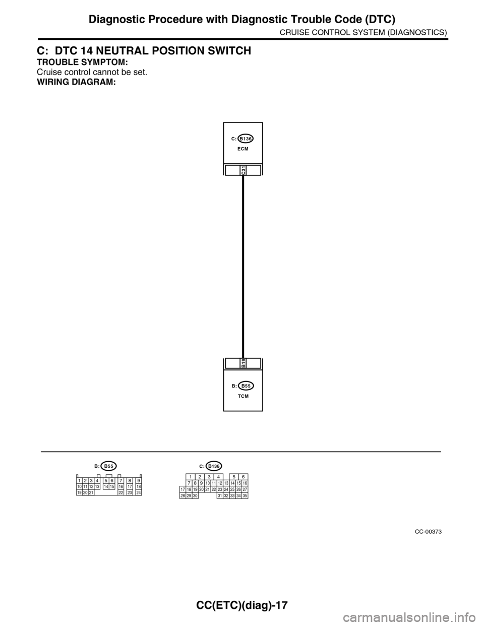
C: DTC 14 NEUTRAL POSITION SWITCH
TROUBLE SYMPTOM:
Cruise control cannot be set.
WIRING DIAGRAM:
CC-00373
B136
ECM
C31
C:
B19
B55
TCM
B:
12341011 1219 20 21135614 1578916 17 1822 23 24
B55B:C:B136
16101112131415252430
9871718192028212223293231
123456
2726333435
Page 185 of 2453
CC(ETC)(diag)-18
Diagnostic Procedure with Diagnostic Trouble Code (DTC)
CRUISE CONTROL SYSTEM (DIAGNOSTICS)
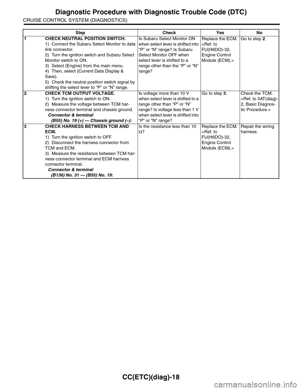
Step Check Yes No
1CHECK NEUTRAL POSITION SWITCH.
1) Connect the Subaru Select Monitor to data
link connector.
2) Turn the ignition switch and Subaru Select
Monitor switch to ON.
3) Select {Engine} from the main menu.
4) Then, select {Current Data Display &
Save}.
5) Check the neutral position switch signal by
shifting the select lever to “P” or “N” range.
Is Subaru Select Monitor ON
when select lever is shifted into
“P” or “N” range? Is Subaru
Select Monitor OFF when
select lever is shifted to a
range other than the “P” or “N”
range?
Replace the ECM.
Engine Control
Module (ECM).>
Go to step 2.
2CHECK TCM OUTPUT VOLTAGE.
1) Turn the ignition switch to ON.
2) Measure the voltage between TCM har-
ness connector terminal and chassis ground.
Connector & terminal
(B55) No. 19 (+) — Chassis ground (–):
Is voltage more than 10 V
when select lever is shifted to a
range other than “P” or “N”
range? Is voltage less than 1 V
when select lever is shifted into
“P” or “N” range?
Go to step 3.Check the TCM.
tic Procedure.>
3CHECK HARNESS BETWEEN TCM AND
ECM.
1) Turn the ignition switch to OFF.
2) Disconnect the harness connector from
TCM and ECM.
3) Measure the resistance between TCM har-
ness connector terminal and ECM harness
connector terminal.
Connector & terminal
(B136) No. 31 — (B55) No. 19:
Is the resistance less than 10
Ω?
Replace the ECM.
Engine Control
Module (ECM).>
Repair the wiring
harness.
Page 186 of 2453
CC(ETC)(diag)-19
Diagnostic Procedure with Diagnostic Trouble Code (DTC)
CRUISE CONTROL SYSTEM (DIAGNOSTICS)
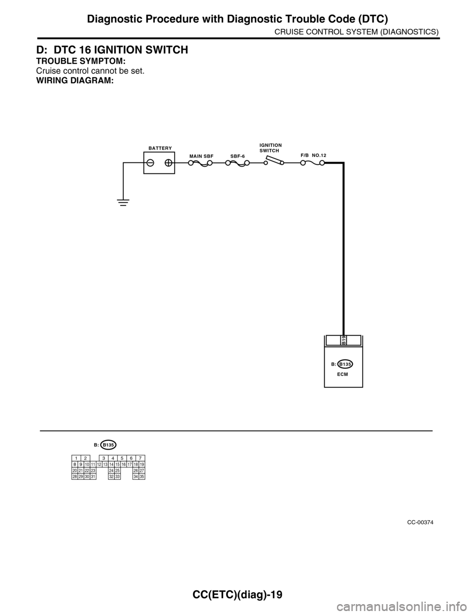
D: DTC 16 IGNITION SWITCH
TROUBLE SYMPTOM:
Cruise control cannot be set.
WIRING DIAGRAM:
CC-00374
B135
ECM
B19
B:
MAIN SBFF/B NO.12SBF-6
BATTERYIGNITIONSWITCH
B:B135
5672134
29
101112131415252416
30
98171819202821222332312627333435
Page 187 of 2453
CC(ETC)(diag)-20
Diagnostic Procedure with Diagnostic Trouble Code (DTC)
CRUISE CONTROL SYSTEM (DIAGNOSTICS)
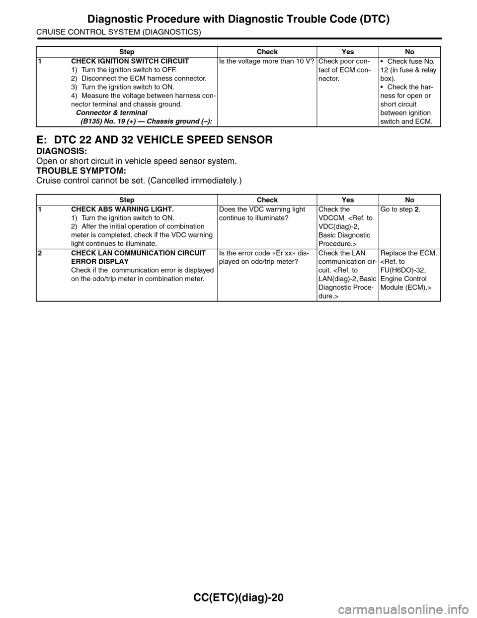
E: DTC 22 AND 32 VEHICLE SPEED SENSOR
DIAGNOSIS:
Open or short circuit in vehicle speed sensor system.
TROUBLE SYMPTOM:
Cruise control cannot be set. (Cancelled immediately.)
Step Check Yes No
1 CHECK IGNITION SWITCH CIRCUIT
1) Turn the ignition switch to OFF.
2) Disconnect the ECM harness connector.
3) Turn the ignition switch to ON.
4) Measure the voltage between harness con-
nector terminal and chassis ground.
Connector & terminal
(B135) No. 19 (+) — Chassis ground (–):
Is the voltage more than 10 V? Check poor con-
tact of ECM con-
nector.
•Check fuse No.
12 (in fuse & relay
box).
•Check the har-
ness for open or
short circuit
between ignition
switch and ECM.
Step Check Yes No
1CHECK ABS WARNING LIGHT.
1) Turn the ignition switch to ON.
2) After the initial operation of combination
meter is completed, check if the VDC warning
light continues to illuminate.
Does the VDC warning light
continue to illuminate?
Check the
VDCCM.
Basic Diagnostic
Procedure.>
Go to step 2.
2CHECK LAN COMMUNICATION CIRCUIT
ERROR DISPLAY
Check if the communication error is displayed
on the odo/trip meter in combination meter.
Is the error code «Er xx» dis-
played on odo/trip meter?
Check the LAN
communication cir-
cuit.
Diagnostic Proce-
dure.>
Replace the ECM.
Engine Control
Module (ECM).>
Page 188 of 2453
ET-2
General Description
ENTERTAINMENT
1. General Description
A: CAUTION
•Before disassembling or reassembling parts, al-
ways disconnect the battery ground cable from bat-
tery.
•When replacing the audio, control module and
other parts provided with memory functions, record
the memory contents before disconnecting the bat-
tery ground cable. Otherwise, the memory is
cleared.
•Reassemble the parts in the reverse order of dis-
assembly procedure unless otherwise indicated.
•Adjust parts to the given specifications.
•Connect the connectors securely during reas-
sembly.
•After reassembly, make sure functional parts op-
erate smoothly.
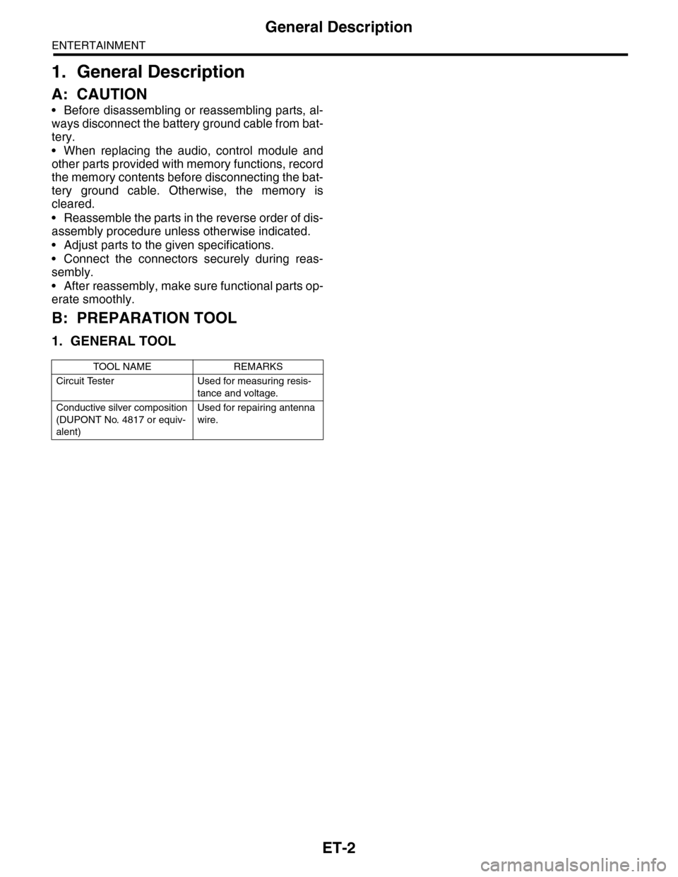
B: PREPARATION TOOL
1. GENERAL TOOL
TOOL NAME REMARKS
Circuit Tester Used for measuring resis-
tance and voltage.
Conductive silver composition
(DUPONT No. 4817 or equiv-
alent)
Used for repairing antenna
wire.
Page 233 of 2453
EB-14
Front Hood
EXTERIOR BODY PANELS
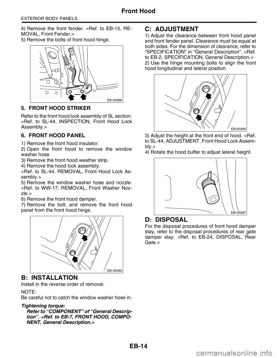
4) Remove the front fender.
5) Remove the bolts of front hood hinge.
5. FRONT HOOD STRIKER
Refer to the front hood lock assembly of SL section.
6. FRONT HOOD PANEL
1) Remove the front hood insulator.
2) Open the front hood to remove the window
washer hose.
3) Remove the front hood weather strip.
4) Remove the hood lock assembly.
5) Remove the window washer hose and nozzle.
6) Remove the front hood damper.
7) Remove the bolt, and remove the front hood
panel from the front hood hinge.
B: INSTALLATION
Install in the reverse order of removal.
NOTE:
Be careful not to catch the window washer hose in.
Tightening torque:
Refer to “COMPONENT” of “General Descrip-
tion”.
C: ADJUSTMENT
1) Adjust the clearance between front hood panel
and front fender panel. Clearance must be equal at
both sides. For the dimension of clearance, refer to
“SPECIFICATION” in “General Description”.
2) Use the hinge mounting bolts to align the front
hood longitudinal and lateral position.
3) Adjust the height at the front end of hood.
bly.>
4) Rotate the hood buffer to adjust lateral height.
D: DISPOSAL
For the disposal procedures of front hood damper
stay, refer to the disposal procedures of rear gate
damper stay.
EB-00286
EB-00285
EB-00285
EB-00287
Page 265 of 2453
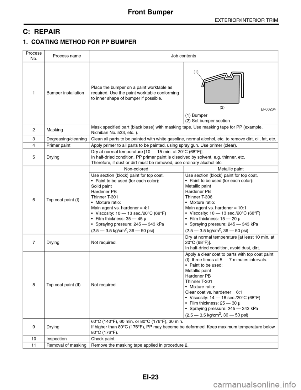
EI-23
Front Bumper
EXTERIOR/INTERIOR TRIM
C: REPAIR
1. COATING METHOD FOR PP BUMPER
Process
No.Process name Job contents
1Bumper installation
Place the bumper on a paint worktable as
required. Use the paint worktable conforming
to inner shape of bumper if possible.
(1) Bumper
(2) Set bumper section
2MaskingMask specified part (black base) with masking tape. Use masking tape for PP (example,
Nichiban No. 533, etc. ).
3Degreasing/cleaningClean all parts to be painted with white gasoline, normal alcohol, etc. to remove dirt, oil, fat, etc.
4Primer paint Apply primer to all parts to be painted, using spray gun. Use primer (clear).
5Drying
Dry at normal temperature [10 — 15 min. at 20°C (68°F)].
In half-dried condition, PP primer paint is dissolved by solvent, e.g. thinner, etc.
Therefore, if dust or dirt must be removed, use ordinary alcohol etc.
6Top coat paint (I)
Non-colored Metallic paint
Use section (block) paint for top coat.
•Paint to be used (for each color):
Solid paint
Hardener PB
Thinner T-301
•Mixture ratio:
Main agent vs. hardener = 4:1
• Viscosity: 10 — 13 sec./20°C (68°F)
•Film thickness: 35 — 45 µ
•Spraying pressure: 245 — 343 kPa
(2.5 — 3.5 kg/cm2, 36 — 50 psi)
Use section (block) paint for top coat.
•Paint to be used (for each color):
Metallic paint
Hardener PB
Thinner T-306
•Mixture ratio:
Main agent vs. hardener = 10:1
•Viscosity: 10 — 13 sec./20°C (68°F)
•Film thickness: 15 — 20 µ
•Spraying pressure: 245 — 343 kPa
(2.5 — 3.5 kg/cm2, 36 — 50 psi)
7Drying Not required.
Dry at normal temperature [at least 10 min. at
20°C (68°F)].
In half-dried condition, avoid dust, dirt.
8Top coat paint (II)Not required.
Apply a clear coat to parts with top coat paint
(I), three times at 5 — 7 minutes intervals.
•Paint to be used:
Metallic paint
Hardener PB
Thinner T-301
•Mixture ratio:
Clear coat vs. hardener = 6:1
•Viscosity: 14 — 16 sec./20°C (68°F)
•Film thickness: 25 — 30 µ
•Spraying pressure: 245 — 343 kPa
(2.5 — 3.5 kg/cm2, 36 — 50 psi)
9Drying
60°C (140°F), 60 min. or 80°C (176°F), 30 min.
If higher than 80°C (176°F), PP may become be deformed. Keep maximum temperature below
80°C (176°F).
10 Inspection Check paint.
11 Removal of masking Remove the masking tape applied in procedure 2.
EI-00234(2)
(1)
Page 267 of 2453
EI-25
Front Bumper
EXTERIOR/INTERIOR TRIM
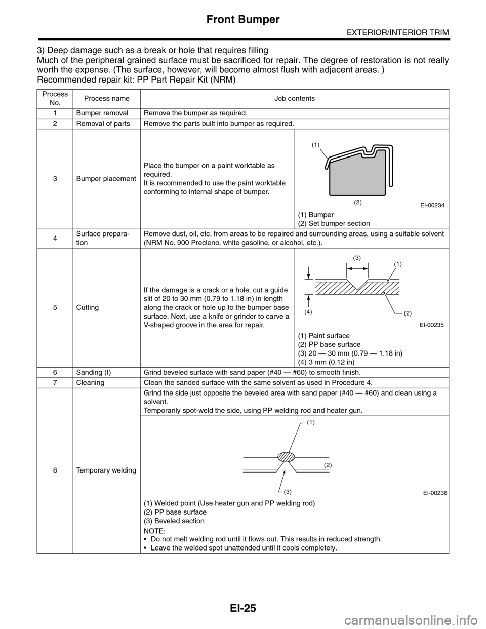
3) Deep damage such as a break or hole that requires filling
Much of the peripheral grained surface must be sacrificed for repair. The degree of restoration is not really
worth the expense. (The surface, however, will become almost flush with adjacent areas. )
Recommended repair kit: PP Part Repair Kit (NRM)
Process
No.Process name Job contents
1Bumper removalRemove the bumper as required.
2Removal of partsRemove the parts built into bumper as required.
3Bumper placement
Place the bumper on a paint worktable as
required.
It is recommended to use the paint worktable
conforming to internal shape of bumper.
(1) Bumper
(2) Set bumper section
4Surface prepara-
tion
Remove dust, oil, etc. from areas to be repaired and surrounding areas, using a suitable solvent
(NRM No. 900 Precleno, white gasoline, or alcohol, etc.).
5Cutting
If the damage is a crack or a hole, cut a guide
slit of 20 to 30 mm (0.79 to 1.18 in) in length
along the crack or hole up to the bumper base
surface. Next, use a knife or grinder to carve a
V- s h a p e d g r o o ve i n t h e a r e a f o r r e p a i r.
(1) Paint surface
(2) PP base surface
(3) 20 — 30 mm (0.79 — 1.18 in)
(4) 3 mm (0.12 in)
6Sanding (I) Grind beveled surface with sand paper (#40 — #60) to smooth finish.
7Cleaning Clean the sanded surface with the same solvent as used in Procedure 4.
8Temporary welding
Grind the side just opposite the beveled area with sand paper (#40 — #60) and clean using a
solvent.
Te m p o r a r i l y s p o t - w e l d t h e s i d e , u s i n g P P w e l d i n g r o d a n d h e a t e r g u n .
(1) Welded point (Use heater gun and PP welding rod)
(2) PP base surface
(3) Beveled section
NOTE:•Do not melt welding rod until it flows out. This results in reduced strength.
•Leave the welded spot unattended until it cools completely.
EI-00234(2)
(1)
EI-00235
(4)(2)
(1)(3)
EI-00236
(1)
(2)
(3)