coolant temperature sensor SUBARU TRIBECA 2009 1.G Service User Guide
[x] Cancel search | Manufacturer: SUBARU, Model Year: 2009, Model line: TRIBECA, Model: SUBARU TRIBECA 2009 1.GPages: 2453, PDF Size: 46.32 MB
Page 1185 of 2453
EN(H6DO)(diag)-24
General Scan Tool
ENGINE (DIAGNOSTICS)
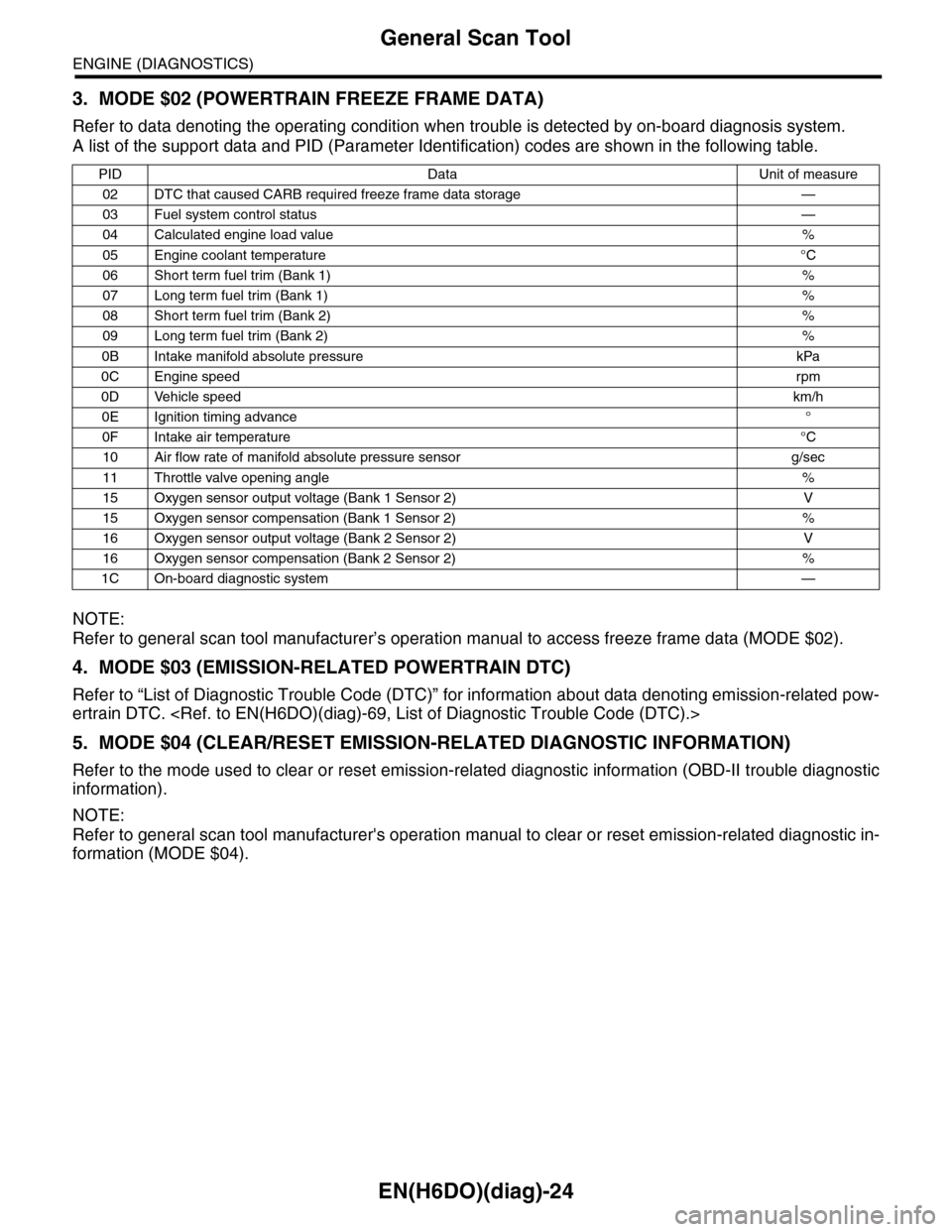
3. MODE $02 (POWERTRAIN FREEZE FRAME DATA)
Refer to data denoting the operating condition when trouble is detected by on-board diagnosis system.
A list of the support data and PID (Parameter Identification) codes are shown in the following table.
NOTE:
Refer to general scan tool manufacturer’s operation manual to access freeze frame data (MODE $02).
4. MODE $03 (EMISSION-RELATED POWERTRAIN DTC)
Refer to “List of Diagnostic Trouble Code (DTC)” for information about data denoting emission-related pow-
ertrain DTC.
5. MODE $04 (CLEAR/RESET EMISSION-RELATED DIAGNOSTIC INFORMATION)
Refer to the mode used to clear or reset emission-related diagnostic information (OBD-II trouble diagnostic
information).
NOTE:
Refer to general scan tool manufacturer's operation manual to clear or reset emission-related diagnostic in-
formation (MODE $04).
PID Data Unit of measure
02 DTC that caused CARB required freeze frame data storage —
03 Fuel system control status—
04 Calculated engine load value%
05 Engine coolant temperature°C
06 Short term fuel trim (Bank 1)%
07 Long term fuel trim (Bank 1)%
08 Short term fuel trim (Bank 2)%
09 Long term fuel trim (Bank 2)%
0B Intake manifold absolute pressure kPa
0C Engine speedrpm
0D Vehicle speedkm/h
0E Ignition timing advance°
0F Intake air temperature°C
10 Air flow rate of manifold absolute pressure sensor g/sec
11 Throttle valve opening angle%
15 Oxygen sensor output voltage (Bank 1 Sensor 2) V
15 Oxygen sensor compensation (Bank 1 Sensor 2) %
16 Oxygen sensor output voltage (Bank 2 Sensor 2) V
16 Oxygen sensor compensation (Bank 2 Sensor 2) %
1C On-board diagnostic system—
Page 1188 of 2453
![SUBARU TRIBECA 2009 1.G Service User Guide EN(H6DO)(diag)-27
Subaru Select Monitor
ENGINE (DIAGNOSTICS)
4. READ CURRENT DATA FOR ENGINE (NORMAL MODE)
1) On the «Main Menu» display screen, select the {Each System Check} and press the [YES] ke SUBARU TRIBECA 2009 1.G Service User Guide EN(H6DO)(diag)-27
Subaru Select Monitor
ENGINE (DIAGNOSTICS)
4. READ CURRENT DATA FOR ENGINE (NORMAL MODE)
1) On the «Main Menu» display screen, select the {Each System Check} and press the [YES] ke](/img/17/7322/w960_7322-1187.png)
EN(H6DO)(diag)-27
Subaru Select Monitor
ENGINE (DIAGNOSTICS)
4. READ CURRENT DATA FOR ENGINE (NORMAL MODE)
1) On the «Main Menu» display screen, select the {Each System Check} and press the [YES] key.
2) On the «System Selection Menu» display screen, select the {Engine} and press the [YES] key.
3) Press the [YES] key after the information of engine type has been displayed.
4) On the «Engine Diagnosis» display screen, select the {Current Data Display/Save}, and then press the
[YES] key.
5) On the «Data Display Menu» screen, select the {Data Display} and press the [YES] key.
6) Using the scroll key, scroll the display screen up or down until the desired data is shown.
•A list of the support data is shown in the following table.
Description Display Unit of measure Note (at idling)
Engine load Engine load % 3.5%
Engine coolant temperature signal Coolant Temp. °C or °F≥ 75°C or 167°F (After
engine is warmed-up.)
A/F compensation 1 A/F Compensation 1 % 3.1%
A/F learning 1 A/F learning 1 % 0.0%
A/F compensation 2 A/F Compensation 2 % 4.7%
A/F learning 2 A/F learning 2 % 0.0%
Intake manifold absolute pressure Mani. Absolute PressuremmHg, kPa,
inHg or psig
200 — 300 mmHg, 26.7 —
40 kPa, 7.8 — 11.8 inHg or
3.8 — 5.8 psig
Engine speed signal Engine speed rpm 600 — 800 rpm
Meter vehicle speed signal Meter vehicle speed km/h or MPH 0 km/h or 0 MPH
Ignition timing signal Ignition timing deg 13 — 15 deg
Intake air temperature signal Intake air temperature °C or °F (Ambient air temperature)
Amount of intake air Mass Air Flow g/s or lb/m 3.8 g/s or 0.5 lb/m
Throttle opening angle signal Throttle valve angle % 1.2 — 1.6%
Fr o nt ox yg e n se n so r vo lt a g e val ue 1Fr o n t oxy ge n s en s or vol t ag e
value 1V0.035 V
Fr o nt ox yg e n se n so r vo lt a g e val ue 2Fr o n t oxy ge n s en s or vol t ag e
value 2V0.020 V
Battery voltage Battery Voltage V 12 — 14 V
Mass air flow voltage Mass air flow voltage V 1.1 — 1.2 V
Injection 1 pulse width Injection 1 pulse width ms 2.82 ms
Injection 2 pulse width Injection 2 pulse width ms 2.82 ms
Knock sensor compensation Knock correction deg 0 deg
Atmospheric pressure signal Atmospheric pressuremmHg, kPa,
inHg or psig(Atmospheric pressure)
Intake manifold relative pressureIntake manifold relative pres-
sure
mmHg, kPa,
inHg or psig
(Intake manifold absolute
pressure — atmospheric
pressure)
Acceleration opening angle signal Acceleration opening angle % 0%
Radiator fan output Radiator fan output % 0%
Purge control solenoid valve duty ratio CPC Duty % 0 — 3%
Generator duty ALT duty % 0%
Fuel pump duty Fuel pump duty % 33%
Va r i a b l e va l v e t i m i n g a d v a n c e a n g l e a m o u n t R V V T a d va n c e a n g l e a m o u n t R d e g 0 d e g
Va r i a b l e va l v e t i m i n g a d v a n c e a n g l e a m o u n t L V V T a d va n c e a n g l e a m o u n t L d e g 0 d e g
Oil flow control solenoid valve duty R OCV duty R % 9.4%
Oil flow control solenoid valve duty L OCV duty L % 9.4%
Oil flow control solenoid valve current R OCV current R mA 64 mA
Oil flow control solenoid valve current L OCV current L mA 64 mA
Fr o nt ox yg e n ( A / F) s en so r cu r r en t va l ue 1 A / F s en s or cu r r e nt va l ue 1 mA 0 . 0 m A
Fr o nt ox yg e n ( A / F) s en so r cu r r en t va l ue 2 A / F s en s or cu r r e nt va l ue 2 mA 0 . 0 m A
Fr o nt ox yg e n ( A / F) s en so r r es is t an ce val ue 1 A / F s en s or r e si st a nc e val u e 1Ω31 Ω
Page 1192 of 2453
![SUBARU TRIBECA 2009 1.G Service User Guide EN(H6DO)(diag)-31
Subaru Select Monitor
ENGINE (DIAGNOSTICS)
6. READ FREEZE FRAME DATA FOR ENGINE (OBD MODE)
1) On the «Main Menu» display screen, select the {Each System Check} and press the [YES] SUBARU TRIBECA 2009 1.G Service User Guide EN(H6DO)(diag)-31
Subaru Select Monitor
ENGINE (DIAGNOSTICS)
6. READ FREEZE FRAME DATA FOR ENGINE (OBD MODE)
1) On the «Main Menu» display screen, select the {Each System Check} and press the [YES]](/img/17/7322/w960_7322-1191.png)
EN(H6DO)(diag)-31
Subaru Select Monitor
ENGINE (DIAGNOSTICS)
6. READ FREEZE FRAME DATA FOR ENGINE (OBD MODE)
1) On the «Main Menu» display screen, select the {Each System Check} and press the [YES] key.
2) On the «System Selection Menu» display screen, select the {Engine} and press the [YES] key.
3) Press the [YES] key after the information of engine type has been displayed.
4) On the «Engine Diagnosis» display screen, select the {OBD System} and press the [YES] key.
5) On the «OBD Menu» display screen, select the {Freeze Frame Data} and press the [YES] key.
•A list of the support data is shown in the following table.
NOTE:
For detailed operation procedure, refer to the “SUBARU SELECT MONITOR OPERATION MANUAL”.
Description Display Unit of measure
DTC of freeze frame data Freeze frame data DTC
Air fuel ratio control system for bank 1 Fuel system for Bank1 —
Air fuel ratio control system for bank 2 Fuel system for Bank2 —
Engine load data Engine Load %
Engine coolant temperature signal Coolant Temp. °C or °F
Short term fuel trim by front oxygen (A/F) sensor (Bank 1) Short term fuel trim B1 %
Long term fuel trim by front oxygen (A/F) sensor (Bank 1) Long term fuel trim B1 %
Short term fuel trim by front oxygen (A/F) sensor (Bank 2) Short term fuel trim B2 %
Long term fuel trim by front oxygen (A/F) sensor (Bank 2) Long term fuel trim B2 %
Intake manifold absolute pressure signal Mani. Absolute Pressure mmHg, kPa, inHg or psig
Engine speed signal Engine Speed rpm
Ve h i c l e s p e e d s i g n a l Ve h i c l e S p e e d k m / h o r M P H
Ignition timing #1 Ignition timing adv. #1 °
Intake air temperature Intake Air Temp. °C
Amount of intake air Mass Air Flow g/s
Throttle valve angle Throttle Opening Angle %
Oxygen sensor #12 Oxygen sensor #12 V
A/F compensation #12 Short term fuel trim #12 %
Oxygen sensor #22 Oxygen sensor #22 V
A/F compensation #12 Short term fuel trim #22 %
Oxygen sensor #11 Oxygen sensor #11 support
Oxygen sensor #12 Oxygen sensor #12 support
Oxygen sensor #21 Oxygen sensor #21 support
Oxygen sensor #22 Oxygen sensor #22 support
Page 1196 of 2453
EN(H6DO)(diag)-35
Inspection Mode
ENGINE (DIAGNOSTICS)
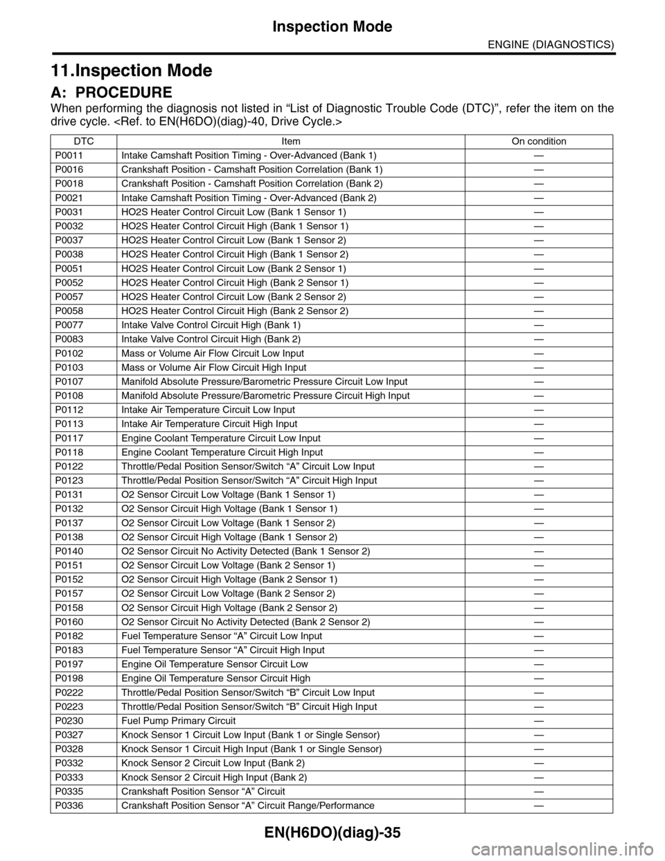
11.Inspection Mode
A: PROCEDURE
When performing the diagnosis not listed in “List of Diagnostic Trouble Code (DTC)”, refer the item on the
drive cycle.
DTC Item On condition
P0011 Intake Camshaft Position Timing - Over-Advanced (Bank 1) —
P0016 Crankshaft Position - Camshaft Position Correlation (Bank 1) —
P0018 Crankshaft Position - Camshaft Position Correlation (Bank 2) —
P0021 Intake Camshaft Position Timing - Over-Advanced (Bank 2) —
P0031 HO2S Heater Control Circuit Low (Bank 1 Sensor 1) —
P0032 HO2S Heater Control Circuit High (Bank 1 Sensor 1) —
P0037 HO2S Heater Control Circuit Low (Bank 1 Sensor 2) —
P0038 HO2S Heater Control Circuit High (Bank 1 Sensor 2) —
P0051 HO2S Heater Control Circuit Low (Bank 2 Sensor 1) —
P0052 HO2S Heater Control Circuit High (Bank 2 Sensor 1) —
P0057 HO2S Heater Control Circuit Low (Bank 2 Sensor 2) —
P0058 HO2S Heater Control Circuit High (Bank 2 Sensor 2) —
P0077 Intake Valve Control Circuit High (Bank 1) —
P0083 Intake Valve Control Circuit High (Bank 2) —
P0102 Mass or Volume Air Flow Circuit Low Input —
P0103 Mass or Volume Air Flow Circuit High Input —
P0107 Manifold Absolute Pressure/Barometric Pressure Circuit Low Input —
P0108 Manifold Absolute Pressure/Barometric Pressure Circuit High Input —
P0112 Intake Air Temperature Circuit Low Input —
P0113 Intake Air Temperature Circuit High Input —
P0117 Engine Coolant Temperature Circuit Low Input —
P0118 Engine Coolant Temperature Circuit High Input —
P0122 Throttle/Pedal Position Sensor/Switch “A” Circuit Low Input —
P0123 Throttle/Pedal Position Sensor/Switch “A” Circuit High Input —
P0131 O2 Sensor Circuit Low Voltage (Bank 1 Sensor 1) —
P0132 O2 Sensor Circuit High Voltage (Bank 1 Sensor 1) —
P0137 O2 Sensor Circuit Low Voltage (Bank 1 Sensor 2) —
P0138 O2 Sensor Circuit High Voltage (Bank 1 Sensor 2) —
P0140 O2 Sensor Circuit No Activity Detected (Bank 1 Sensor 2) —
P0151 O2 Sensor Circuit Low Voltage (Bank 2 Sensor 1) —
P0152 O2 Sensor Circuit High Voltage (Bank 2 Sensor 1) —
P0157 O2 Sensor Circuit Low Voltage (Bank 2 Sensor 2) —
P0158 O2 Sensor Circuit High Voltage (Bank 2 Sensor 2) —
P0160 O2 Sensor Circuit No Activity Detected (Bank 2 Sensor 2) —
P0182 Fuel Temperature Sensor “A” Circuit Low Input —
P0183 Fuel Temperature Sensor “A” Circuit High Input —
P0197 Engine Oil Temperature Sensor Circuit Low —
P0198 Engine Oil Temperature Sensor Circuit High —
P0222 Throttle/Pedal Position Sensor/Switch “B” Circuit Low Input —
P0223 Throttle/Pedal Position Sensor/Switch “B” Circuit High Input —
P0230 Fuel Pump Primary Circuit —
P0327 Knock Sensor 1 Circuit Low Input (Bank 1 or Single Sensor) —
P0328 Knock Sensor 1 Circuit High Input (Bank 1 or Single Sensor) —
P0332 Knock Sensor 2 Circuit Low Input (Bank 2) —
P0333 Knock Sensor 2 Circuit High Input (Bank 2) —
P0335 Crankshaft Position Sensor “A” Circuit —
P0336 Crankshaft Position Sensor “A” Circuit Range/Performance —
Page 1202 of 2453
EN(H6DO)(diag)-41
Drive Cycle
ENGINE (DIAGNOSTICS)
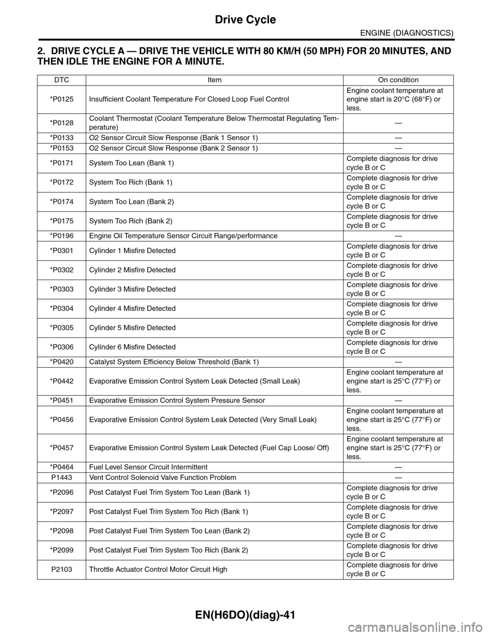
2. DRIVE CYCLE A — DRIVE THE VEHICLE WITH 80 KM/H (50 MPH) FOR 20 MINUTES, AND
THEN IDLE THE ENGINE FOR A MINUTE.
DTC Item On condition
*P0125 Insufficient Coolant Temperature For Closed Loop Fuel Control
Engine coolant temperature at
engine start is 20°C (68°F) or
less.
*P0128Coolant Thermostat (Coolant Temperature Below Thermostat Regulating Tem-
perature)—
*P0133 O2 Sensor Circuit Slow Response (Bank 1 Sensor 1) —
*P0153 O2 Sensor Circuit Slow Response (Bank 2 Sensor 1) —
*P0171 System Too Lean (Bank 1)Complete diagnosis for drive
cycle B or C
*P0172 System Too Rich (Bank 1)Complete diagnosis for drive
cycle B or C
*P0174 System Too Lean (Bank 2)Complete diagnosis for drive
cycle B or C
*P0175 System Too Rich (Bank 2)Complete diagnosis for drive
cycle B or C
*P0196 Engine Oil Temperature Sensor Circuit Range/performance —
*P0301 Cylinder 1 Misfire DetectedComplete diagnosis for drive
cycle B or C
*P0302 Cylinder 2 Misfire DetectedComplete diagnosis for drive
cycle B or C
*P0303 Cylinder 3 Misfire DetectedComplete diagnosis for drive
cycle B or C
*P0304 Cylinder 4 Misfire DetectedComplete diagnosis for drive
cycle B or C
*P0305 Cylinder 5 Misfire DetectedComplete diagnosis for drive
cycle B or C
*P0306 Cylinder 6 Misfire DetectedComplete diagnosis for drive
cycle B or C
*P0420 Catalyst System Efficiency Below Threshold (Bank 1) —
*P0442 Evaporative Emission Control System Leak Detected (Small Leak)
Engine coolant temperature at
engine start is 25°C (77°F) or
less.
*P0451 Evaporative Emission Control System Pressure Sensor —
*P0456 Evaporative Emission Control System Leak Detected (Very Small Leak)
Engine coolant temperature at
engine start is 25°C (77°F) or
less.
*P0457 Evaporative Emission Control System Leak Detected (Fuel Cap Loose/ Off)
Engine coolant temperature at
engine start is 25°C (77°F) or
less.
*P0464 Fuel Level Sensor Circuit Intermittent —
P1443 Vent Control Solenoid Valve Function Problem —
*P2096 Post Catalyst Fuel Trim System Too Lean (Bank 1)Complete diagnosis for drive
cycle B or C
*P2097 Post Catalyst Fuel Trim System Too Rich (Bank 1)Complete diagnosis for drive
cycle B or C
*P2098 Post Catalyst Fuel Trim System Too Lean (Bank 2)Complete diagnosis for drive
cycle B or C
*P2099 Post Catalyst Fuel Trim System Too Rich (Bank 2)Complete diagnosis for drive
cycle B or C
P2103 Throttle Actuator Control Motor Circuit HighComplete diagnosis for drive
cycle B or C
Page 1205 of 2453
EN(H6DO)(diag)-44
Drive Cycle
ENGINE (DIAGNOSTICS)
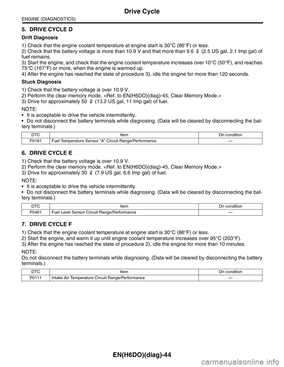
5. DRIVE CYCLE D
Drift Diagnosis
1) Check that the engine coolant temperature at engine start is 30°C (86°F) or less.
2) Check that the battery voltage is more than 10.9 V and that more than 9.6 2 (2.5 US gal, 2.1 Imp gal) of
fuel remains.
3) Start the engine, and check that the engine coolant temperature increases over 10°C (50°F), and reaches
75°C (167°F) or more, when the engine is warmed up.
4) After the engine has reached the state of procedure 3), idle the engine for more than 120 seconds.
Stuck Diagnosis
1) Check that the battery voltage is over 10.9 V.
2) Perform the clear memory mode.
3) Drive for approximately 50 2 (13.2 US gal, 11 Imp gal) of fuel.
NOTE:
•It is acceptable to drive the vehicle intermittently.
•Do not disconnect the battery terminals while diagnosing. (Data will be cleared by disconnecting the bat-
tery terminals.)
6. DRIVE CYCLE E
1) Check that the battery voltage is over 10.9 V.
2) Perform the clear memory mode.
3) Drive for approximately 30 2 (7.9 US gal, 6.6 Imp gal) of fuel.
NOTE:
•It is acceptable to drive the vehicle intermittently.
•Do not disconnect the battery terminals while diagnosing. (Data will be cleared by disconnecting the bat-
tery terminals.)
7. DRIVE CYCLE F
1) Check that the engine coolant temperature at engine start is 30°C (86°F) or less.
2) Start the engine, and warm it up until engine coolant temperature increases over 95°C (203°F).
3) After the engine has reached the state of procedure 2), idle the engine for more than 10 minutes.
NOTE:
Do not disconnect the battery terminals while diagnosing. (Data will be cleared by disconnecting the battery
terminals.)
DTC Item On condition
P0181 Fuel Temperature Sensor “A” Circuit Range/Performance —
DTC Item On condition
P0461 Fuel Level Sensor Circuit Range/Performance —
DTC Item On condition
P0111 Intake Air Temperature Circuit Range/Performance —
Page 1231 of 2453
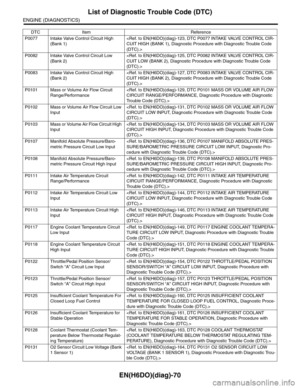
EN(H6DO)(diag)-70
List of Diagnostic Trouble Code (DTC)
ENGINE (DIAGNOSTICS)
P0077 Intake Valve Control Circuit High
(Bank 1)
(DTC).>
P0082 Intake Valve Control Circuit Low
(Bank 2)
(DTC).>
P0083 Intake Valve Control Circuit High
(Bank 2)
(DTC).>
P0101 Mass or Volume Air Flow Circuit
Range/Performance
Tr o u b l e C o d e ( D T C ) . >
P0102 Mass or Volume Air Flow Circuit Low
Input
(DTC).>
P0103 Mass or Volume Air Flow Circuit High
Input
(DTC).>
P0107 Manifold Absolute Pressure/Baro-
metric Pressure Circuit Low Input
cedure with Diagnostic Trouble Code (DTC).>
P0108 Manifold Absolute Pressure/Baro-
metric Pressure Circuit High Input
cedure with Diagnostic Trouble Code (DTC).>
P0111 Intake Air Temperature Circuit
Range/Performance
Tr o u b l e C o d e ( D T C ) . >
P0112 Intake Air Temperature Circuit Low
Input
(DTC).>
P0113 Intake Air Temperature Circuit High
Input
(DTC).>
P0117 Engine Coolant Temperature Circuit
Low Input
Code (DTC).>
P0118 Engine Coolant Temperature Circuit
High Input
Code (DTC).>
P0122 Throttle/Pedal Position Sensor/
Switch “A” Circuit Low Input
Diagnostic Trouble Code (DTC).>
P0123 Throttle/Pedal Position Sensor/
Switch “A” Circuit High Input
Diagnostic Trouble Code (DTC).>
P0125 Insufficient Coolant Temperature For
Closed Loop Fuel Control
dure with Diagnostic Trouble Code (DTC).>
P0126 Insufficient Coolant Temperature for
Stable Operation
Diagnostic Trouble Code (DTC).>
P0128 Coolant Thermostat (Coolant Tem-
perature Below Thermostat Regulat-
ing Temperature)
PERATURE), Diagnostic Procedure with Diagnostic Trouble Code (DTC).>
P0131 O2 Sensor Circuit Low Voltage (Bank
1 Sensor 1)
ble Code (DTC).>
DTC Item Reference
Page 1304 of 2453
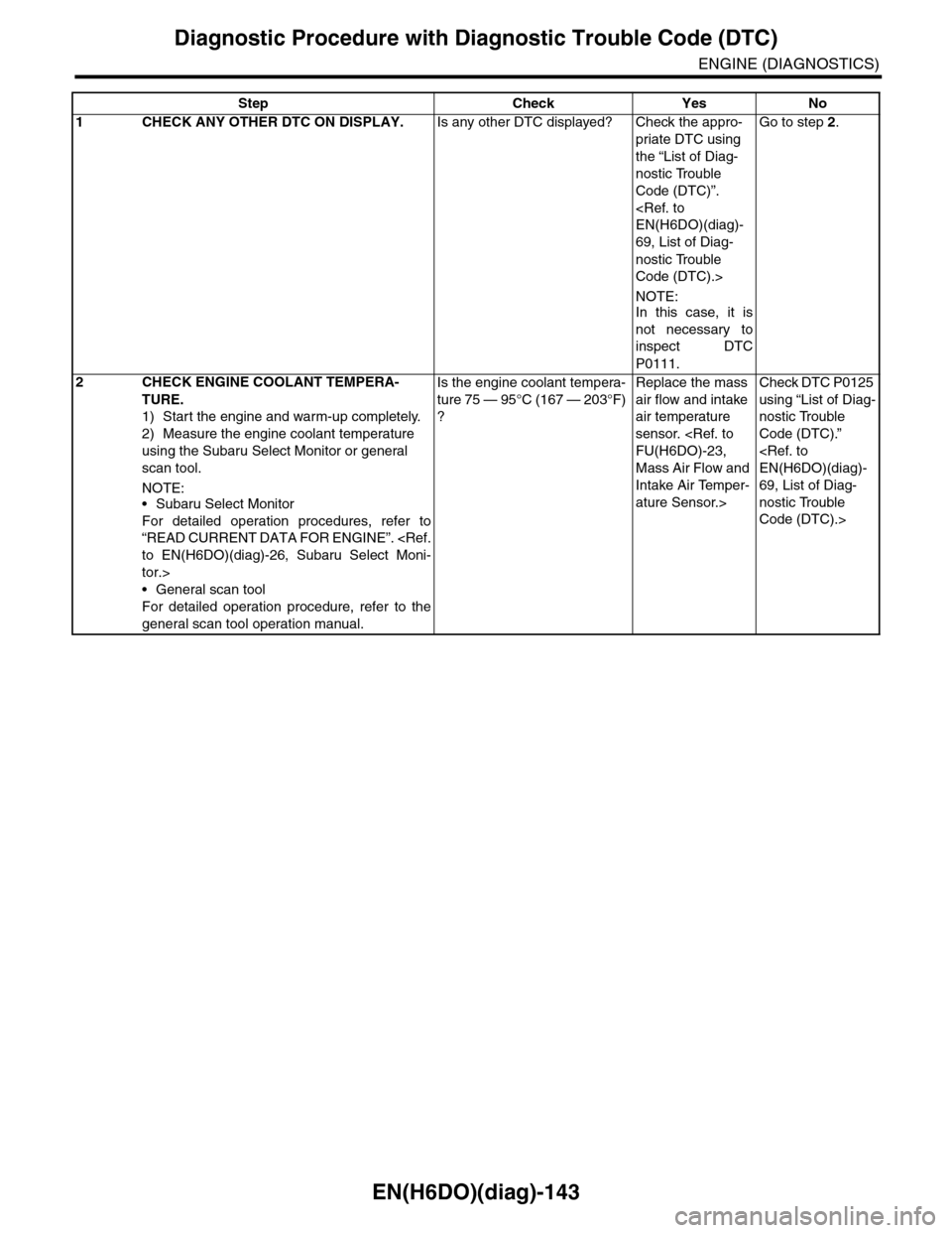
EN(H6DO)(diag)-143
Diagnostic Procedure with Diagnostic Trouble Code (DTC)
ENGINE (DIAGNOSTICS)
Step Check Yes No
1CHECK ANY OTHER DTC ON DISPLAY.Is any other DTC displayed? Check the appro-
priate DTC using
the “List of Diag-
nostic Trouble
Code (DTC)”.
69, List of Diag-
nostic Trouble
Code (DTC).>
NOTE:In this case, it is
not necessary to
inspect DTC
P0111.
Go to step 2.
2CHECK ENGINE COOLANT TEMPERA-
TURE.
1) Start the engine and warm-up completely.
2) Measure the engine coolant temperature
using the Subaru Select Monitor or general
scan tool.
NOTE:•Subaru Select Monitor
For detailed operation procedures, refer to
“READ CURRENT DATA FOR ENGINE”.
tor.>
•General scan tool
For detailed operation procedure, refer to the
general scan tool operation manual.
Is the engine coolant tempera-
ture 75 — 95°C (167 — 203°F)
?
Replace the mass
air flow and intake
air temperature
sensor.
Mass Air Flow and
Intake Air Temper-
ature Sensor.>
Check DTC P0125
using “List of Diag-
nostic Trouble
Code (DTC).”
69, List of Diag-
nostic Trouble
Code (DTC).>
Page 1310 of 2453
EN(H6DO)(diag)-149
Diagnostic Procedure with Diagnostic Trouble Code (DTC)
ENGINE (DIAGNOSTICS)
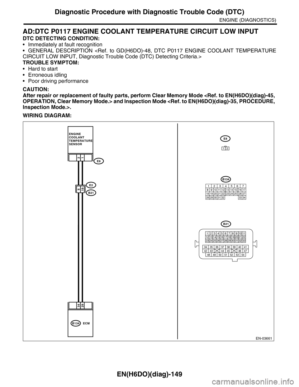
AD:DTC P0117 ENGINE COOLANT TEMPERATURE CIRCUIT LOW INPUT
DTC DETECTING CONDITION:
•Immediately at fault recognition
•GENERAL DESCRIPTION
TROUBLE SYMPTOM:
•Hard to start
•Erroneous idling
•Poor driving performance
CAUTION:
After repair or replacement of faulty parts, perform Clear Memory Mode
WIRING DIAGRAM:
EN-03661
2934
198
B134ECM
12
E2
B21
E8
ENGINECOOLANTTEMPERATURE SENSOR
E8
B21
123412131415567816171819910 1120212223 24 25 2627 28 29 3031 32 33
3534 37363938 41404342 4445 47464948 51505352 54
12
B134
85610 11 12 13 14 157213416
3019 20 2228 29
91718252123 24323126 2733 34
Page 1311 of 2453
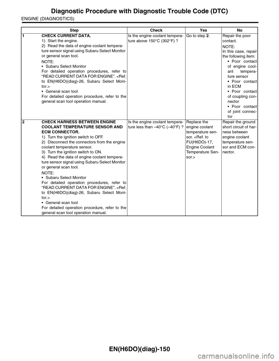
EN(H6DO)(diag)-150
Diagnostic Procedure with Diagnostic Trouble Code (DTC)
ENGINE (DIAGNOSTICS)
Step Check Yes No
1CHECK CURRENT DATA.
1) Start the engine.
2) Read the data of engine coolant tempera-
ture sensor signal using Subaru Select Monitor
or general scan tool.
NOTE:
•Subaru Select Monitor
For detailed operation procedures, refer to
“READ CURRENT DATA FOR ENGINE”.
tor.>
•General scan tool
For detailed operation procedure, refer to the
general scan tool operation manual.
Is the engine coolant tempera-
ture above 150°C (302°F) ?
Go to step 2.Repair the poor
contact.
NOTE:
In this case, repair
the following item:
•Poor contact
of engine cool-
ant tempera-
ture sensor
•Poor contact
in ECM
•Poor contact
of coupling con-
nector
•Poor contact
of joint connec-
tor
2CHECK HARNESS BETWEEN ENGINE
COOLANT TEMPERATURE SENSOR AND
ECM CONNECTOR.
1) Turn the ignition switch to OFF.
2) Disconnect the connectors from the engine
coolant temperature sensor.
3) Turn the ignition switch to ON.
4) Read the data of engine coolant tempera-
ture sensor signal using Subaru Select Monitor
or general scan tool.
NOTE:•Subaru Select Monitor
For detailed operation procedures, refer to
“READ CURRENT DATA FOR ENGINE”.
tor.>
•General scan tool
For detailed operation procedure, refer to the
general scan tool operation manual.
Is the engine coolant tempera-
ture less than –40°C (–40°F) ?
Replace the
engine coolant
temperature sen-
sor.
Engine Coolant
Te m p e r a t u r e S e n -
sor.>
Repair the ground
short circuit of har-
ness between
engine coolant
temperature sen-
sor and ECM con-
nector.