coolant temperature sensor SUBARU TRIBECA 2009 1.G Service Repair Manual
[x] Cancel search | Manufacturer: SUBARU, Model Year: 2009, Model line: TRIBECA, Model: SUBARU TRIBECA 2009 1.GPages: 2453, PDF Size: 46.32 MB
Page 1516 of 2453
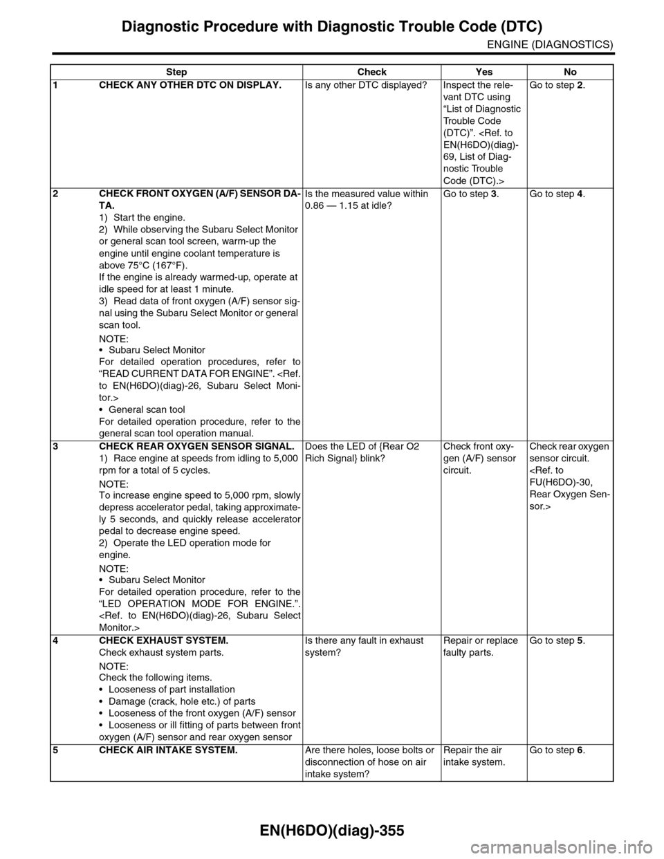
EN(H6DO)(diag)-355
Diagnostic Procedure with Diagnostic Trouble Code (DTC)
ENGINE (DIAGNOSTICS)
Step Check Yes No
1CHECK ANY OTHER DTC ON DISPLAY.Is any other DTC displayed? Inspect the rele-
vant DTC using
“List of Diagnostic
Tr o u b l e C o d e
(DTC)”.
69, List of Diag-
nostic Trouble
Code (DTC).>
Go to step 2.
2CHECK FRONT OXYGEN (A/F) SENSOR DA-
TA.
1) Start the engine.
2) While observing the Subaru Select Monitor
or general scan tool screen, warm-up the
engine until engine coolant temperature is
above 75°C (167°F).
If the engine is already warmed-up, operate at
idle speed for at least 1 minute.
3) Read data of front oxygen (A/F) sensor sig-
nal using the Subaru Select Monitor or general
scan tool.
NOTE:
•Subaru Select Monitor
For detailed operation procedures, refer to
“READ CURRENT DATA FOR ENGINE”.
tor.>
•General scan tool
For detailed operation procedure, refer to the
general scan tool operation manual.
Is the measured value within
0.86 — 1.15 at idle?
Go to step 3.Go to step 4.
3CHECK REAR OXYGEN SENSOR SIGNAL.
1) Race engine at speeds from idling to 5,000
rpm for a total of 5 cycles.
NOTE:To increase engine speed to 5,000 rpm, slowly
depress accelerator pedal, taking approximate-
ly 5 seconds, and quickly release accelerator
pedal to decrease engine speed.
2) Operate the LED operation mode for
engine.
NOTE:•Subaru Select Monitor
For detailed operation procedure, refer to the
“LED OPERATION MODE FOR ENGINE.”.
Does the LED of {Rear O2
Rich Signal} blink?
Check front oxy-
gen (A/F) sensor
circuit.
Check rear oxygen
sensor circuit.
Rear Oxygen Sen-
sor.>
4 CHECK EXHAUST SYSTEM.
Check exhaust system parts.
NOTE:Check the following items.
•Looseness of part installation
•Damage (crack, hole etc.) of parts
•Looseness of the front oxygen (A/F) sensor
•Looseness or ill fitting of parts between front
oxygen (A/F) sensor and rear oxygen sensor
Is there any fault in exhaust
system?
Repair or replace
faulty par ts.
Go to step 5.
5CHECK AIR INTAKE SYSTEM.Are there holes, loose bolts or
disconnection of hose on air
intake system?
Repair the air
intake system.
Go to step 6.
Page 1517 of 2453
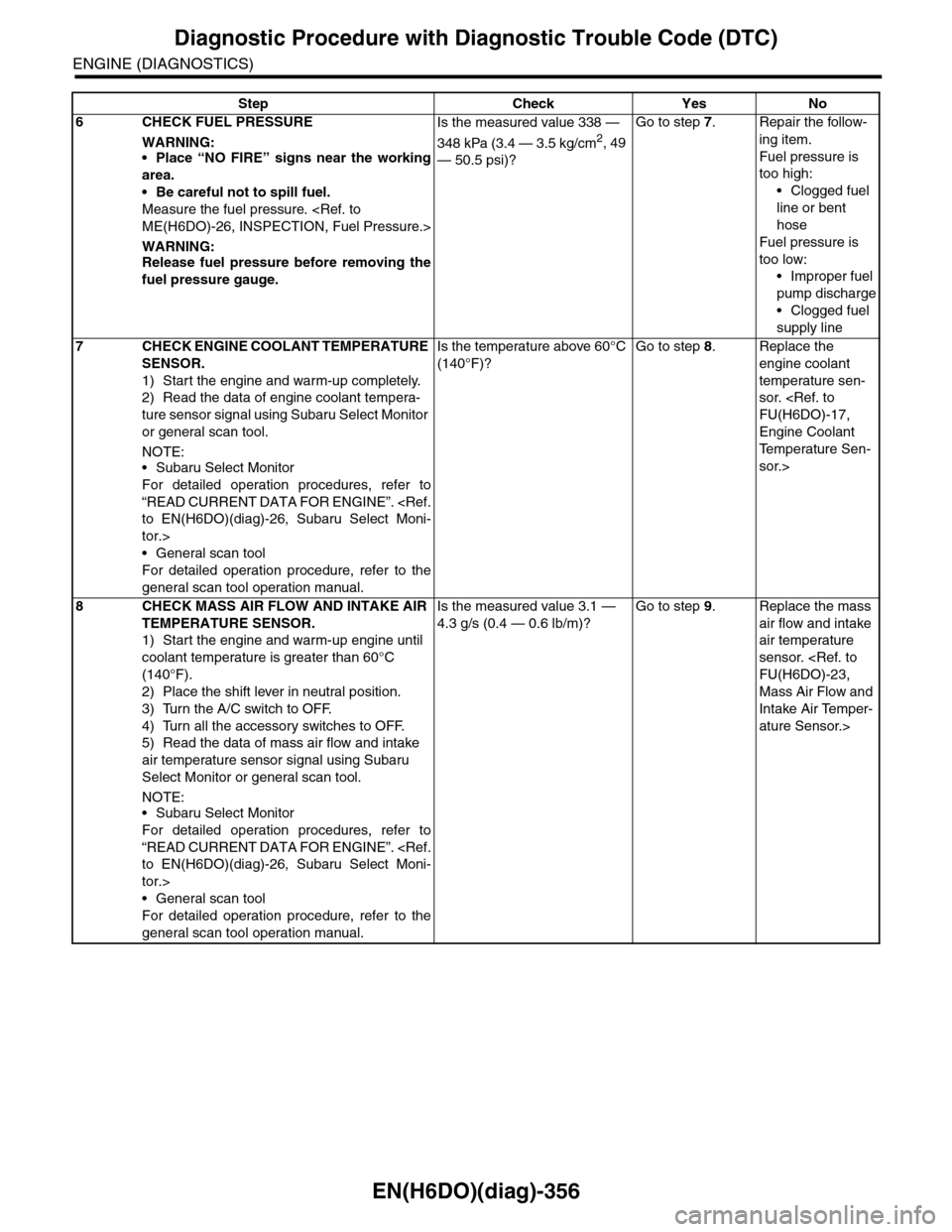
EN(H6DO)(diag)-356
Diagnostic Procedure with Diagnostic Trouble Code (DTC)
ENGINE (DIAGNOSTICS)
6CHECK FUEL PRESSURE
WARNING:•Place “NO FIRE” signs near the working
area.
•Be careful not to spill fuel.
Measure the fuel pressure.
WARNING:Release fuel pressure before removing the
fuel pressure gauge.
Is the measured value 338 —
348 kPa (3.4 — 3.5 kg/cm2, 49
— 50.5 psi)?
Go to step 7.Repair the follow-
ing item.
Fuel pressure is
too high:
•Clogged fuel
line or bent
hose
Fuel pressure is
too low:
•Improper fuel
pump discharge
•Clogged fuel
supply line
7CHECK ENGINE COOLANT TEMPERATURE
SENSOR.
1) Start the engine and warm-up completely.
2) Read the data of engine coolant tempera-
ture sensor signal using Subaru Select Monitor
or general scan tool.
NOTE:•Subaru Select Monitor
For detailed operation procedures, refer to
“READ CURRENT DATA FOR ENGINE”.
tor.>
•General scan tool
For detailed operation procedure, refer to the
general scan tool operation manual.
Is the temperature above 60°C
(140°F)?
Go to step 8.Replace the
engine coolant
temperature sen-
sor.
Engine Coolant
Te m p e r a t u r e S e n -
sor.>
8CHECK MASS AIR FLOW AND INTAKE AIR
TEMPERATURE SENSOR.
1) Start the engine and warm-up engine until
coolant temperature is greater than 60°C
(140°F).
2) Place the shift lever in neutral position.
3) Turn the A/C switch to OFF.
4) Turn all the accessory switches to OFF.
5) Read the data of mass air flow and intake
air temperature sensor signal using Subaru
Select Monitor or general scan tool.
NOTE:•Subaru Select Monitor
For detailed operation procedures, refer to
“READ CURRENT DATA FOR ENGINE”.
tor.>
•General scan tool
For detailed operation procedure, refer to the
general scan tool operation manual.
Is the measured value 3.1 —
4.3 g/s (0.4 — 0.6 lb/m)?
Go to step 9.Replace the mass
air flow and intake
air temperature
sensor.
Mass Air Flow and
Intake Air Temper-
ature Sensor.>
Step Check Yes No
Page 1518 of 2453
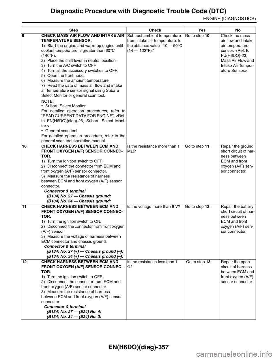
EN(H6DO)(diag)-357
Diagnostic Procedure with Diagnostic Trouble Code (DTC)
ENGINE (DIAGNOSTICS)
9CHECK MASS AIR FLOW AND INTAKE AIR
TEMPERATURE SENSOR.
1) Start the engine and warm-up engine until
coolant temperature is greater than 60°C
(140°F).
2) Place the shift lever in neutral position.
3) Turn the A/C switch to OFF.
4) Turn all the accessory switches to OFF.
5) Open the front hood.
6) Measure the ambient temperature.
7) Read the data of mass air flow and intake
air temperature sensor signal using Subaru
Select Monitor or general scan tool.
NOTE:•Subaru Select Monitor
For detailed operation procedures, refer to
“READ CURRENT DATA FOR ENGINE”.
tor.>
•General scan tool
For detailed operation procedure, refer to the
general scan tool operation manual.
Subtract ambient temperature
from intake air temperature. Is
the obtained value –10 — 50°C
(14 — 122°F)?
Go to step 10.Check the mass
air flow and intake
air temperature
sensor.
Mass Air Flow and
Intake Air Temper-
ature Sensor.>
10 CHECK HARNESS BETWEEN ECM AND
FRONT OXYGEN (A/F) SENSOR CONNEC-
TOR.
1) Turn the ignition switch to OFF.
2) Disconnect the connector from ECM and
front oxygen (A/F) sensor connector.
3) Measure the resistance of harness
between ECM and front oxygen (A/F) sensor
connector.
Connector & terminal
(B134) No. 27 — Chassis ground:
(B134) No. 34 — Chassis ground:
Is the resistance more than 1
MΩ?
Go to step 11.Repair the ground
short circuit of har-
ness between
ECM and front
oxygen (A/F) sen-
sor connector.
11 CHECK HARNESS BETWEEN ECM AND
FRONT OXYGEN (A/F) SENSOR CONNEC-
TOR.
1) Turn the ignition switch to ON.
2) Disconnect the connector from front oxygen
(A/F) sensor.
3) Measure the voltage of harness between
ECM connector and chassis ground.
Connector & terminal
(B134) No. 27 (+) — Chassis ground (–):
(B134) No. 34 (+) — Chassis ground (–):
Is the voltage more than 8 V? Go to step 12.Repair the battery
short circuit of har-
ness between
ECM and front
oxygen (A/F) sen-
sor connector.
12 CHECK HARNESS BETWEEN ECM AND
FRONT OXYGEN (A/F) SENSOR CONNEC-
TOR.
1) Turn the ignition switch to OFF.
2) Disconnect the connector from ECM and
front oxygen (A/F) sensor connector.
3) Measure the resistance of harness
between ECM and front oxygen (A/F) sensor
connector.
Connector & terminal
(B134) No. 27 — (E24) No. 4:
(B134) No. 34 — (E24) No. 3:
Is the resistance less than 1
Ω?
Go to step 13.Repair the open
circuit of harness
between ECM and
front oxygen (A/F)
sensor connector.
Step Check Yes No
Page 1519 of 2453

EN(H6DO)(diag)-358
Diagnostic Procedure with Diagnostic Trouble Code (DTC)
ENGINE (DIAGNOSTICS)
13 CHECK REAR OXYGEN SENSOR DATA.
1) Warm-up the engine until engine coolant
temperature is above 70°C (158°F), and keep
the engine speed at 5,000 rpm.
2) Read the data of rear oxygen sensor signal
using Subaru Select Monitor or general scan
tool.
NOTE:•Subaru Select Monitor
For detailed operation procedures, refer to
“READ CURRENT DATA FOR ENGINE”.
tor.>
•General scan tool
For detailed operation procedure, refer to the
general scan tool operation manual.
Is the voltage more than 490
mV?
Go to step 16.Go to step 14.
14 CHECK HARNESS BETWEEN ECM AND
REAR OXYGEN SENSOR CONNECTOR.
1) Turn the ignition switch to OFF.
2) Disconnect the connector from ECM and
rear oxygen sensor.
3) Measure the resistance of harness
between ECM and rear oxygen sensor con-
nector.
Connector & terminal
(B137) No. 25 — (E61) No. 3:
(B136) No. 35 — (E61) No. 4:
Is the resistance more than
3Ω?
Repair the open
circuit of harness
between ECM and
rear oxygen sen-
sor connector.
Go to step 15.
15 CHECK HARNESS BETWEEN REAR OXY-
GEN SENSOR AND ECM CONNECTOR.
1) Turn the ignition switch to OFF.
2) Disconnect the connector from rear oxygen
sensor.
3) Turn the ignition switch to ON.
4) Measure the voltage between rear oxygen
sensor harness connector and chassis ground.
Connector & terminal
(E25) No. 3 (+) — Chassis ground (–):
Is the voltage 0.2 — 0.5 V? Replace the rear
oxygen sensor.
Rear Oxygen Sen-
sor.>
Repair the har-
ness and connec-
tor.
NOTE:In this case, repair
the following item:
•Open circuit
of harness be-
tween rear oxy-
gen sensor and
ECM connector
•Poor contact
in rear oxygen
sensor connec-
tor
•Poor contact
in ECM connec-
tor
Step Check Yes No
Page 1520 of 2453
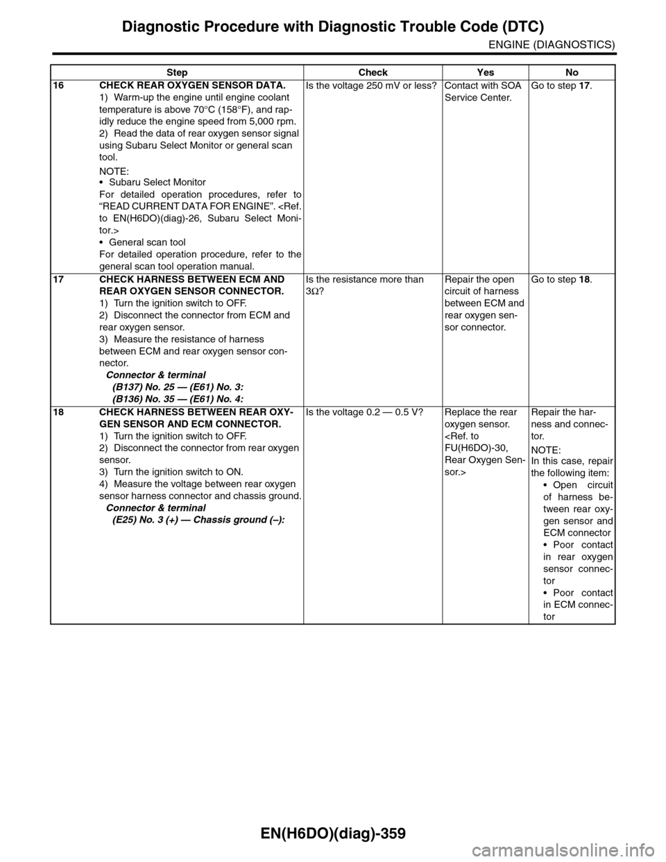
EN(H6DO)(diag)-359
Diagnostic Procedure with Diagnostic Trouble Code (DTC)
ENGINE (DIAGNOSTICS)
16 CHECK REAR OXYGEN SENSOR DATA.
1) Warm-up the engine until engine coolant
temperature is above 70°C (158°F), and rap-
idly reduce the engine speed from 5,000 rpm.
2) Read the data of rear oxygen sensor signal
using Subaru Select Monitor or general scan
tool.
NOTE:•Subaru Select Monitor
For detailed operation procedures, refer to
“READ CURRENT DATA FOR ENGINE”.
tor.>
•General scan tool
For detailed operation procedure, refer to the
general scan tool operation manual.
Is the voltage 250 mV or less? Contact with SOA
Service Center.
Go to step 17.
17 CHECK HARNESS BETWEEN ECM AND
REAR OXYGEN SENSOR CONNECTOR.
1) Turn the ignition switch to OFF.
2) Disconnect the connector from ECM and
rear oxygen sensor.
3) Measure the resistance of harness
between ECM and rear oxygen sensor con-
nector.
Connector & terminal
(B137) No. 25 — (E61) No. 3:
(B136) No. 35 — (E61) No. 4:
Is the resistance more than
3Ω?
Repair the open
circuit of harness
between ECM and
rear oxygen sen-
sor connector.
Go to step 18.
18 CHECK HARNESS BETWEEN REAR OXY-
GEN SENSOR AND ECM CONNECTOR.
1) Turn the ignition switch to OFF.
2) Disconnect the connector from rear oxygen
sensor.
3) Turn the ignition switch to ON.
4) Measure the voltage between rear oxygen
sensor harness connector and chassis ground.
Connector & terminal
(E25) No. 3 (+) — Chassis ground (–):
Is the voltage 0.2 — 0.5 V? Replace the rear
oxygen sensor.
Rear Oxygen Sen-
sor.>
Repair the har-
ness and connec-
tor.
NOTE:In this case, repair
the following item:
•Open circuit
of harness be-
tween rear oxy-
gen sensor and
ECM connector
•Poor contact
in rear oxygen
sensor connec-
tor
•Poor contact
in ECM connec-
tor
Step Check Yes No
Page 1553 of 2453
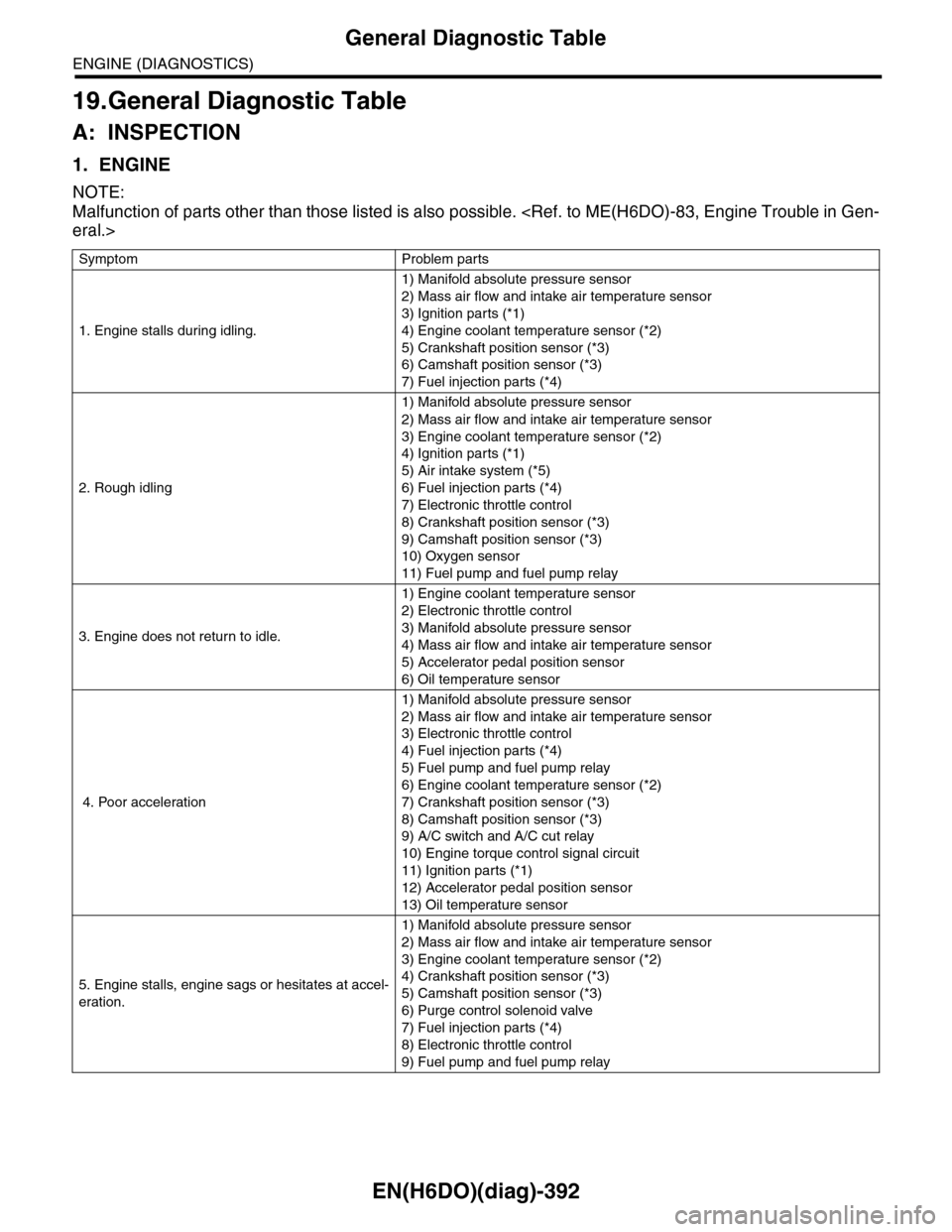
EN(H6DO)(diag)-392
General Diagnostic Table
ENGINE (DIAGNOSTICS)
19.General Diagnostic Table
A: INSPECTION
1. ENGINE
NOTE:
Malfunction of parts other than those listed is also possible.
Symptom Problem parts
1. Engine stalls during idling.
1) Manifold absolute pressure sensor
2) Mass air flow and intake air temperature sensor
3) Ignition parts (*1)
4) Engine coolant temperature sensor (*2)
5) Crankshaft position sensor (*3)
6) Camshaft position sensor (*3)
7) Fuel injection parts (*4)
2. Rough idling
1) Manifold absolute pressure sensor
2) Mass air flow and intake air temperature sensor
3) Engine coolant temperature sensor (*2)
4) Ignition parts (*1)
5) Air intake system (*5)
6) Fuel injection parts (*4)
7) Electronic throttle control
8) Crankshaft position sensor (*3)
9) Camshaft position sensor (*3)
10) Oxygen sensor
11) Fuel pump and fuel pump relay
3. Engine does not return to idle.
1) Engine coolant temperature sensor
2) Electronic throttle control
3) Manifold absolute pressure sensor
4) Mass air flow and intake air temperature sensor
5) Accelerator pedal position sensor
6) Oil temperature sensor
4. Poor acceleration
1) Manifold absolute pressure sensor
2) Mass air flow and intake air temperature sensor
3) Electronic throttle control
4) Fuel injection parts (*4)
5) Fuel pump and fuel pump relay
6) Engine coolant temperature sensor (*2)
7) Crankshaft position sensor (*3)
8) Camshaft position sensor (*3)
9) A/C switch and A/C cut relay
10) Engine torque control signal circuit
11) Ignition parts (*1)
12) Accelerator pedal position sensor
13) Oil temperature sensor
5. Engine stalls, engine sags or hesitates at accel-
eration.
1) Manifold absolute pressure sensor
2) Mass air flow and intake air temperature sensor
3) Engine coolant temperature sensor (*2)
4) Crankshaft position sensor (*3)
5) Camshaft position sensor (*3)
6) Purge control solenoid valve
7) Fuel injection parts (*4)
8) Electronic throttle control
9) Fuel pump and fuel pump relay
Page 1554 of 2453
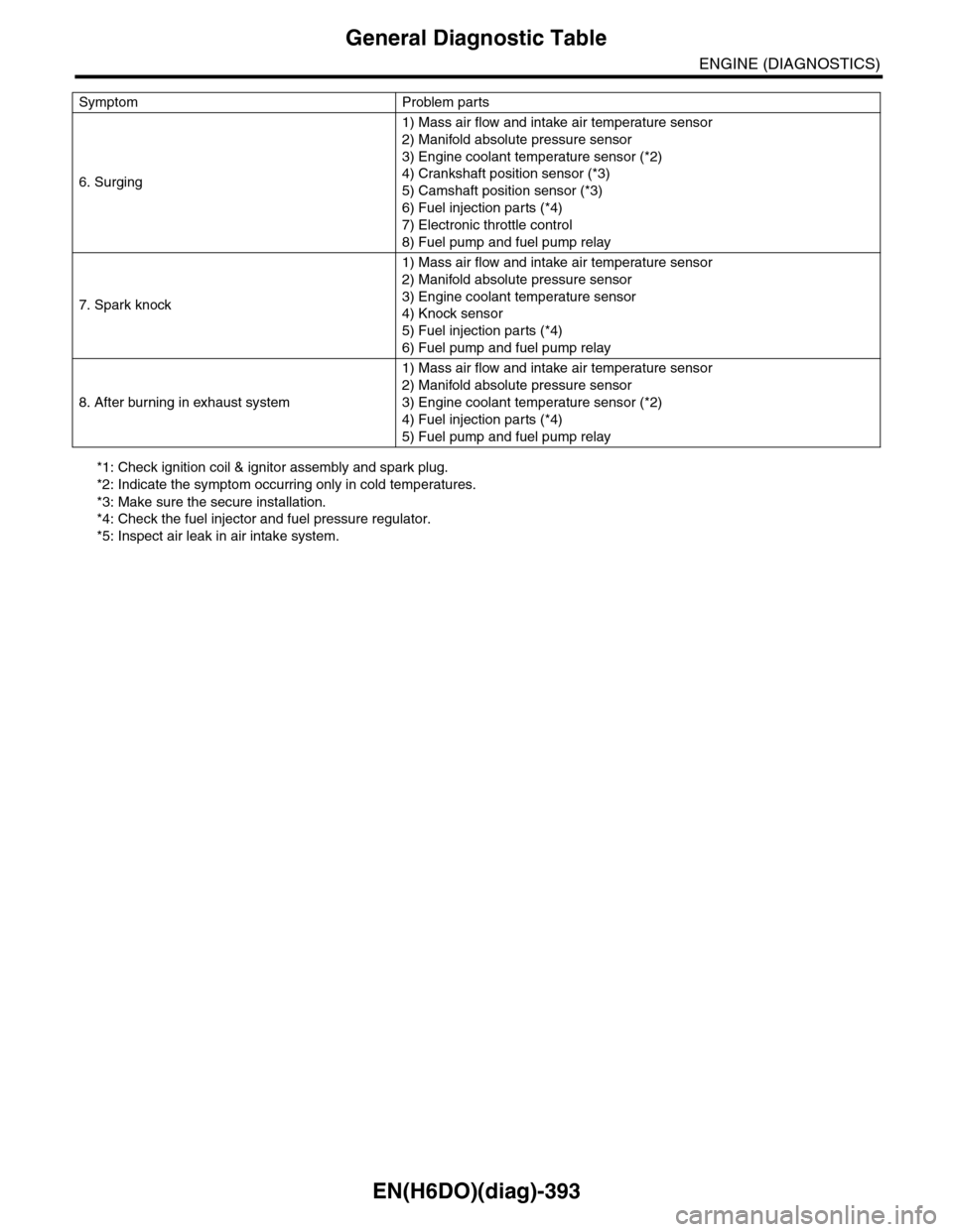
EN(H6DO)(diag)-393
General Diagnostic Table
ENGINE (DIAGNOSTICS)
*1: Check ignition coil & ignitor assembly and spark plug.
*2: Indicate the symptom occurring only in cold temperatures.
*3: Make sure the secure installation.
*4: Check the fuel injector and fuel pressure regulator.
*5: Inspect air leak in air intake system.
6. Surging
1) Mass air flow and intake air temperature sensor
2) Manifold absolute pressure sensor
3) Engine coolant temperature sensor (*2)
4) Crankshaft position sensor (*3)
5) Camshaft position sensor (*3)
6) Fuel injection parts (*4)
7) Electronic throttle control
8) Fuel pump and fuel pump relay
7. Spark knock
1) Mass air flow and intake air temperature sensor
2) Manifold absolute pressure sensor
3) Engine coolant temperature sensor
4) Knock sensor
5) Fuel injection parts (*4)
6) Fuel pump and fuel pump relay
8. After burning in exhaust system
1) Mass air flow and intake air temperature sensor
2) Manifold absolute pressure sensor
3) Engine coolant temperature sensor (*2)
4) Fuel injection parts (*4)
5) Fuel pump and fuel pump relay
Symptom Problem parts
Page 1578 of 2453
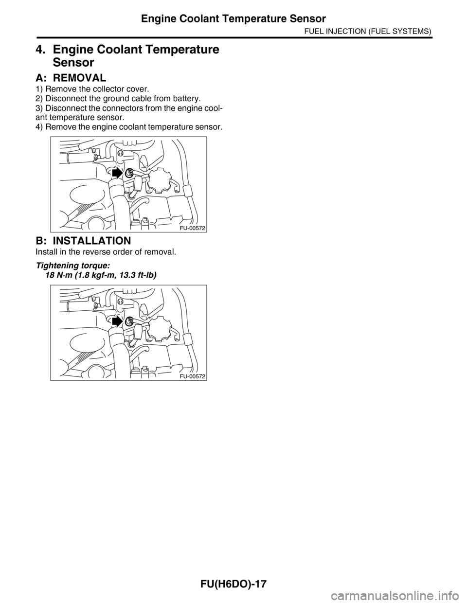
FU(H6DO)-17
Engine Coolant Temperature Sensor
FUEL INJECTION (FUEL SYSTEMS)
4. Engine Coolant Temperature
Sensor
A: REMOVAL
1) Remove the collector cover.
2) Disconnect the ground cable from battery.
3) Disconnect the connectors from the engine cool-
ant temperature sensor.
4) Remove the engine coolant temperature sensor.
B: INSTALLATION
Install in the reverse order of removal.
Tightening torque:
18 N·m (1.8 kgf-m, 13.3 ft-lb)
FU-00572
FU-00572
Page 1615 of 2453
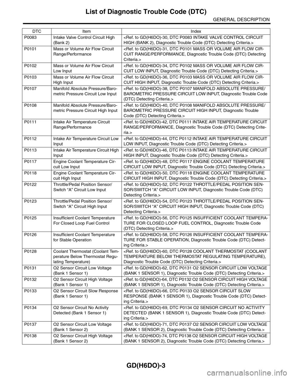
GD(H6DO)-3
List of Diagnostic Trouble Code (DTC)
GENERAL DESCRIPTION
P0083 Intake Valve Control Circuit High
(Bank 2)
P0101 Mass or Volume Air Flow Circuit
Range/Performance
Criteria.>
P0102 Mass or Volume Air Flow Circuit
Low Input
P0103 Mass or Volume Air Flow Circuit
High Input
P0107 Manifold Absolute Pressure/Baro-
metric Pressure Circuit Low Input
(DTC) Detecting Criteria.>
P0108 Manifold Absolute Pressure/Baro-
metric Pressure Circuit High Input
Code (DTC) Detecting Criteria.>
P0111 Intake Air Temperature Circuit
Range/Performance
ria.>
P0112 Intake Air Temperature Circuit Low
Input
P0113 Intake Air Temperature Circuit High
Input
P0117 Engine Coolant Temperature Cir-
cuit Low Input
P0118 Engine Coolant Temperature Cir-
cuit High Input
P0122 Throttle/Pedal Position Sensor/
Switch “A” Circuit Low Input
Detecting Criteria.>
P0123 Throttle/Pedal Position Sensor/
Switch “A” Circuit High Input
Detecting Criteria.>
P0125 Insufficient Coolant Temperature
For Closed Loop Fuel Control
(DTC) Detecting Criteria.>
P0126 Insufficient Coolant Temperature
for Stable Operation
ing Criteria.>
P0128 Coolant Thermostat (Coolant Tem-
perature Below Thermostat Regu-
lating Temperature)
Diagnostic Trouble Code (DTC) Detecting Criteria.>
P0131 O2 Sensor Circuit Low Voltage
(Bank 1 Sensor 1)
P0132 O2 Sensor Circuit High Voltage
(Bank 1 Sensor 1)
P0133 O2 Sensor Circuit Slow Response
(Bank 1 Sensor 1)
ing Criteria.>
P0134 O2 Sensor Circuit No Activity
Detected (Bank 1 Sensor 1)
ing Criteria.>
P0137 O2 Sensor Circuit Low Voltage
(Bank 1 Sensor 2)
P0138 O2 Sensor Circuit High Voltage
(Bank 1 Sensor 2)
DTC Item Index
Page 1638 of 2453
GD(H6DO)-26
Diagnostic Trouble Code (DTC) Detecting Criteria
GENERAL DESCRIPTION
Q: DTC P0068 MAP/MAF - THROTTLE POSITION CORRELATION
1. OUTLINE OF DIAGNOSIS
Detect problems in the intake manifold pressure sensor output properties. Determining from the engine con-
dition, if the intake manifold pressure AD value is small even when operating conditions suggest it should be
large, or if the intake manifold pressure AD value is large even though the operating condition suggest it
should be small, this is judged as being NG.
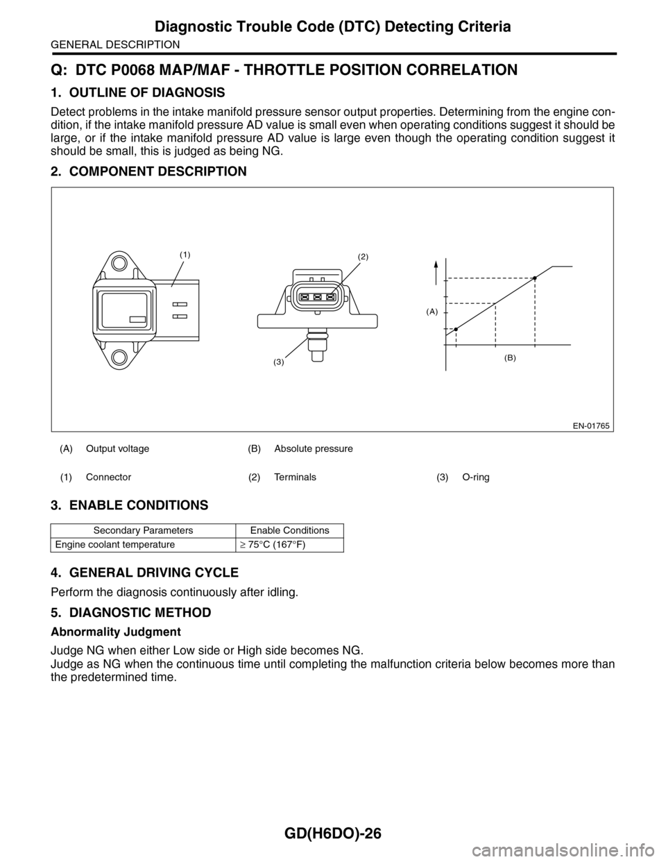
2. COMPONENT DESCRIPTION
3. ENABLE CONDITIONS
4. GENERAL DRIVING CYCLE
Perform the diagnosis continuously after idling.
5. DIAGNOSTIC METHOD
Abnormality Judgment
Judge NG when either Low side or High side becomes NG.
Judge as NG when the continuous time until completing the malfunction criteria below becomes more than
the predetermined time.
(A) Output voltage (B) Absolute pressure
(1) Connector (2) Terminals (3) O-ring
Secondary Parameters Enable Conditions
Engine coolant temperature≥ 75°C (167°F)
EN-01765
(B)
(A)
(2)
(3)
(1)