coolant temperature sensor SUBARU TRIBECA 2009 1.G Service Owner's Manual
[x] Cancel search | Manufacturer: SUBARU, Model Year: 2009, Model line: TRIBECA, Model: SUBARU TRIBECA 2009 1.GPages: 2453, PDF Size: 46.32 MB
Page 1312 of 2453
EN(H6DO)(diag)-151
Diagnostic Procedure with Diagnostic Trouble Code (DTC)
ENGINE (DIAGNOSTICS)
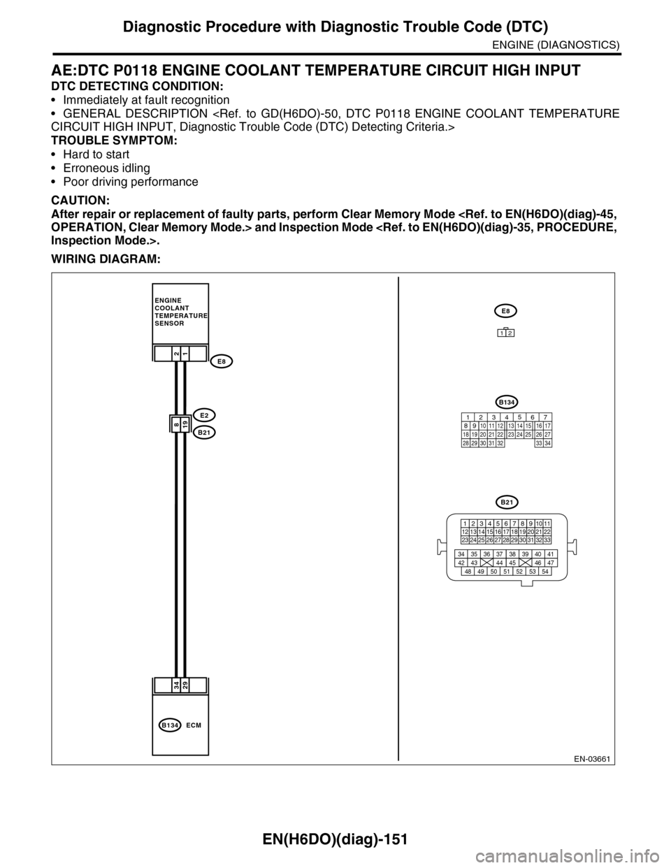
AE:DTC P0118 ENGINE COOLANT TEMPERATURE CIRCUIT HIGH INPUT
DTC DETECTING CONDITION:
•Immediately at fault recognition
•GENERAL DESCRIPTION
TROUBLE SYMPTOM:
•Hard to start
•Erroneous idling
•Poor driving performance
CAUTION:
After repair or replacement of faulty parts, perform Clear Memory Mode
WIRING DIAGRAM:
EN-03661
2934
198
B134ECM
12
E2
B21
E8
ENGINECOOLANTTEMPERATURE SENSOR
E8
B21
123412131415567816171819910 1120212223 24 25 2627 28 29 3031 32 33
3534 37363938 41404342 4445 47464948 51505352 54
12
B134
85610 11 12 13 14 157213416
3019 20 2228 29
91718252123 24323126 2733 34
Page 1313 of 2453
EN(H6DO)(diag)-152
Diagnostic Procedure with Diagnostic Trouble Code (DTC)
ENGINE (DIAGNOSTICS)
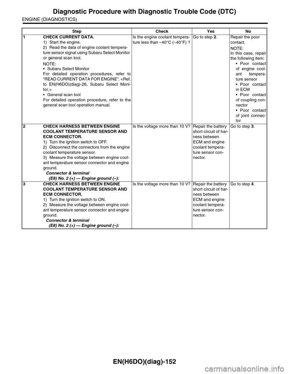
Step Check Yes No
1CHECK CURRENT DATA.
1) Start the engine.
2) Read the data of engine coolant tempera-
ture sensor signal using Subaru Select Monitor
or general scan tool.
NOTE:
•Subaru Select Monitor
For detailed operation procedures, refer to
“READ CURRENT DATA FOR ENGINE”.
tor.>
•General scan tool
For detailed operation procedure, refer to the
general scan tool operation manual.
Is the engine coolant tempera-
ture less than –40°C (–40°F) ?
Go to step 2.Repair the poor
contact.
NOTE:
In this case, repair
the following item:
•Poor contact
of engine cool-
ant tempera-
ture sensor
•Poor contact
in ECM
•Poor contact
of coupling con-
nector
•Poor contact
of joint connec-
tor
2CHECK HARNESS BETWEEN ENGINE
COOLANT TEMPERATURE SENSOR AND
ECM CONNECTOR.
1) Turn the ignition switch to OFF.
2) Disconnect the connectors from the engine
coolant temperature sensor.
3) Measure the voltage between engine cool-
ant temperature sensor connector and engine
ground.
Connector & terminal
(E8) No. 2 (+) — Engine ground (–):
Is the voltage more than 10 V? Repair the battery
short circuit of har-
ness between
ECM and engine
coolant tempera-
ture sensor con-
nector.
Go to step 3.
3CHECK HARNESS BETWEEN ENGINE
COOLANT TEMPERATURE SENSOR AND
ECM CONNECTOR.
1) Turn the ignition switch to ON.
2) Measure the voltage between engine cool-
ant temperature sensor connector and engine
ground.
Connector & terminal
(E8) No. 2 (+) — Engine ground (–):
Is the voltage more than 10 V? Repair the battery
short circuit of har-
ness between
ECM and engine
coolant tempera-
ture sensor con-
nector.
Go to step 4.
Page 1314 of 2453
EN(H6DO)(diag)-153
Diagnostic Procedure with Diagnostic Trouble Code (DTC)
ENGINE (DIAGNOSTICS)
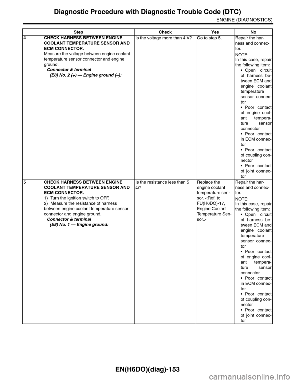
4CHECK HARNESS BETWEEN ENGINE
COOLANT TEMPERATURE SENSOR AND
ECM CONNECTOR.
Measure the voltage between engine coolant
temperature sensor connector and engine
ground.
Connector & terminal
(E8) No. 2 (+) — Engine ground (–):
Is the voltage more than 4 V? Go to step 5.Repair the har-
ness and connec-
tor.
NOTE:In this case, repair
the following item:
•Open circuit
of harness be-
tween ECM and
engine coolant
temperature
sensor connec-
tor
•Poor contact
of engine cool-
ant tempera-
ture sensor
connector
•Poor contact
in ECM connec-
tor
•Poor contact
of coupling con-
nector
•Poor contact
of joint connec-
tor
5CHECK HARNESS BETWEEN ENGINE
COOLANT TEMPERATURE SENSOR AND
ECM CONNECTOR.
1) Turn the ignition switch to OFF.
2) Measure the resistance of harness
between engine coolant temperature sensor
connector and engine ground.
Connector & terminal
(E8) No. 1 — Engine ground:
Is the resistance less than 5
Ω?
Replace the
engine coolant
temperature sen-
sor.
Engine Coolant
Te m p e r a t u r e S e n -
sor.>
Repair the har-
ness and connec-
tor.
NOTE:In this case, repair
the following item:
•Open circuit
of harness be-
tween ECM and
engine coolant
temperature
sensor connec-
tor
•Poor contact
of engine cool-
ant tempera-
ture sensor
connector
•Poor contact
in ECM connec-
tor
•Poor contact
of coupling con-
nector
•Poor contact
of joint connec-
tor
Step Check Yes No
Page 1322 of 2453
EN(H6DO)(diag)-161
Diagnostic Procedure with Diagnostic Trouble Code (DTC)
ENGINE (DIAGNOSTICS)
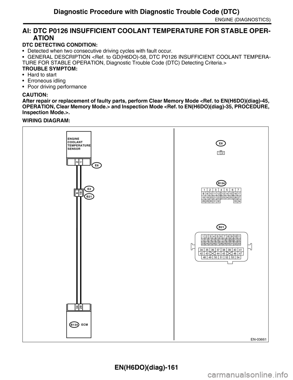
AI: DTC P0126 INSUFFICIENT COOLANT TEMPERATURE FOR STABLE OPER-
ATION
DTC DETECTING CONDITION:
•Detected when two consecutive driving cycles with fault occur.
•GENERAL DESCRIPTION
TROUBLE SYMPTOM:
•Hard to start
•Erroneous idling
•Poor driving performance
CAUTION:
After repair or replacement of faulty parts, perform Clear Memory Mode
WIRING DIAGRAM:
EN-03661
2934
198
B134ECM
12
E2
B21
E8
ENGINECOOLANTTEMPERATURE SENSOR
E8
B21
123412131415567816171819910 1120212223 24 25 2627 28 29 3031 32 33
3534 37363938 41404342 4445 47464948 51505352 54
12
B134
85610 11 12 13 14 157213416
3019 20 2228 29
91718252123 24323126 2733 34
Page 1323 of 2453
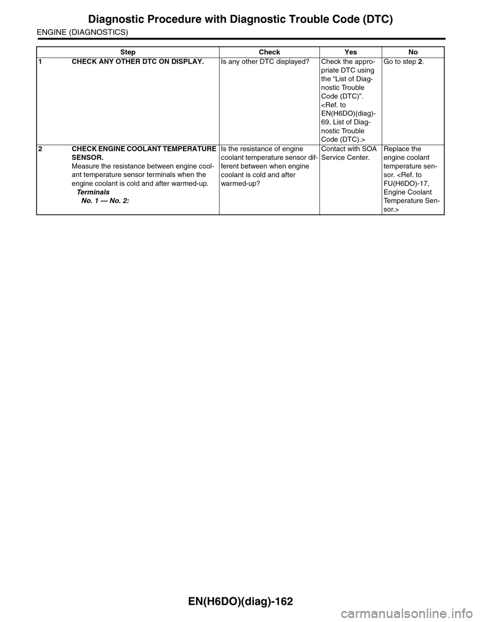
EN(H6DO)(diag)-162
Diagnostic Procedure with Diagnostic Trouble Code (DTC)
ENGINE (DIAGNOSTICS)
Step Check Yes No
1CHECK ANY OTHER DTC ON DISPLAY.Is any other DTC displayed? Check the appro-
priate DTC using
the “List of Diag-
nostic Trouble
Code (DTC)”.
69, List of Diag-
nostic Trouble
Code (DTC).>
Go to step 2.
2CHECK ENGINE COOLANT TEMPERATURE
SENSOR.
Measure the resistance between engine cool-
ant temperature sensor terminals when the
engine coolant is cold and after warmed-up.
Te r m i n a l s
No. 1 — No. 2:
Is the resistance of engine
coolant temperature sensor dif-
ferent between when engine
coolant is cold and after
warmed-up?
Contact with SOA
Service Center.
Replace the
engine coolant
temperature sen-
sor.
Engine Coolant
Te m p e r a t u r e S e n -
sor.>
Page 1339 of 2453
EN(H6DO)(diag)-178
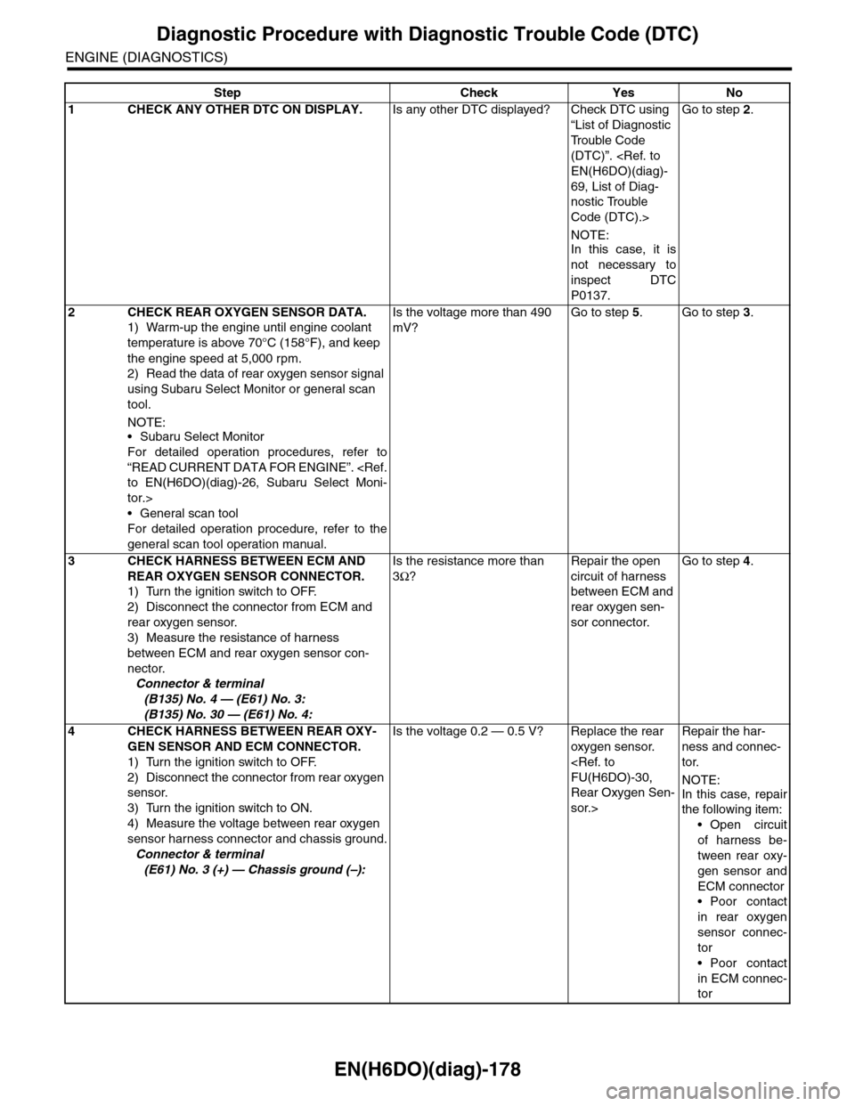
Diagnostic Procedure with Diagnostic Trouble Code (DTC)
ENGINE (DIAGNOSTICS)
Step Check Yes No
1CHECK ANY OTHER DTC ON DISPLAY.Is any other DTC displayed? Check DTC using
“List of Diagnostic
Tr o u b l e C o d e
(DTC)”.
69, List of Diag-
nostic Trouble
Code (DTC).>
NOTE:
In this case, it is
not necessary to
inspect DTC
P0137.
Go to step 2.
2CHECK REAR OXYGEN SENSOR DATA.
1) Warm-up the engine until engine coolant
temperature is above 70°C (158°F), and keep
the engine speed at 5,000 rpm.
2) Read the data of rear oxygen sensor signal
using Subaru Select Monitor or general scan
tool.
NOTE:•Subaru Select Monitor
For detailed operation procedures, refer to
“READ CURRENT DATA FOR ENGINE”.
tor.>
•General scan tool
For detailed operation procedure, refer to the
general scan tool operation manual.
Is the voltage more than 490
mV?
Go to step 5.Go to step 3.
3CHECK HARNESS BETWEEN ECM AND
REAR OXYGEN SENSOR CONNECTOR.
1) Turn the ignition switch to OFF.
2) Disconnect the connector from ECM and
rear oxygen sensor.
3) Measure the resistance of harness
between ECM and rear oxygen sensor con-
nector.
Connector & terminal
(B135) No. 4 — (E61) No. 3:
(B135) No. 30 — (E61) No. 4:
Is the resistance more than
3Ω?
Repair the open
circuit of harness
between ECM and
rear oxygen sen-
sor connector.
Go to step 4.
4CHECK HARNESS BETWEEN REAR OXY-
GEN SENSOR AND ECM CONNECTOR.
1) Turn the ignition switch to OFF.
2) Disconnect the connector from rear oxygen
sensor.
3) Turn the ignition switch to ON.
4) Measure the voltage between rear oxygen
sensor harness connector and chassis ground.
Connector & terminal
(E61) No. 3 (+) — Chassis ground (–):
Is the voltage 0.2 — 0.5 V? Replace the rear
oxygen sensor.
Rear Oxygen Sen-
sor.>
Repair the har-
ness and connec-
tor.
NOTE:
In this case, repair
the following item:
•Open circuit
of harness be-
tween rear oxy-
gen sensor and
ECM connector
•Poor contact
in rear oxygen
sensor connec-
tor
•Poor contact
in ECM connec-
tor
Page 1343 of 2453
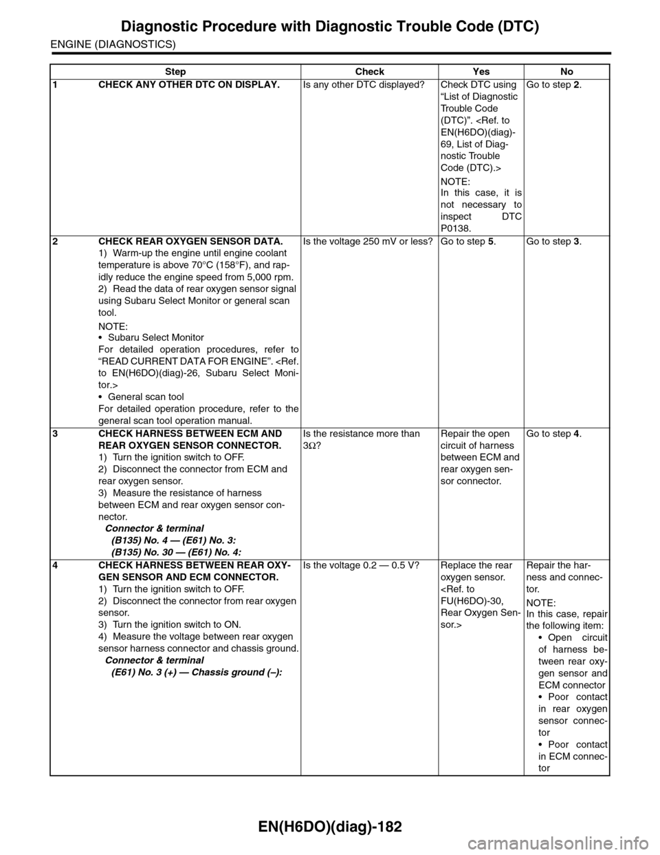
EN(H6DO)(diag)-182
Diagnostic Procedure with Diagnostic Trouble Code (DTC)
ENGINE (DIAGNOSTICS)
Step Check Yes No
1CHECK ANY OTHER DTC ON DISPLAY.Is any other DTC displayed? Check DTC using
“List of Diagnostic
Tr o u b l e C o d e
(DTC)”.
69, List of Diag-
nostic Trouble
Code (DTC).>
NOTE:
In this case, it is
not necessary to
inspect DTC
P0138.
Go to step 2.
2CHECK REAR OXYGEN SENSOR DATA.
1) Warm-up the engine until engine coolant
temperature is above 70°C (158°F), and rap-
idly reduce the engine speed from 5,000 rpm.
2) Read the data of rear oxygen sensor signal
using Subaru Select Monitor or general scan
tool.
NOTE:•Subaru Select Monitor
For detailed operation procedures, refer to
“READ CURRENT DATA FOR ENGINE”.
tor.>
•General scan tool
For detailed operation procedure, refer to the
general scan tool operation manual.
Is the voltage 250 mV or less? Go to step 5.Go to step 3.
3CHECK HARNESS BETWEEN ECM AND
REAR OXYGEN SENSOR CONNECTOR.
1) Turn the ignition switch to OFF.
2) Disconnect the connector from ECM and
rear oxygen sensor.
3) Measure the resistance of harness
between ECM and rear oxygen sensor con-
nector.
Connector & terminal
(B135) No. 4 — (E61) No. 3:
(B135) No. 30 — (E61) No. 4:
Is the resistance more than
3Ω?
Repair the open
circuit of harness
between ECM and
rear oxygen sen-
sor connector.
Go to step 4.
4CHECK HARNESS BETWEEN REAR OXY-
GEN SENSOR AND ECM CONNECTOR.
1) Turn the ignition switch to OFF.
2) Disconnect the connector from rear oxygen
sensor.
3) Turn the ignition switch to ON.
4) Measure the voltage between rear oxygen
sensor harness connector and chassis ground.
Connector & terminal
(E61) No. 3 (+) — Chassis ground (–):
Is the voltage 0.2 — 0.5 V? Replace the rear
oxygen sensor.
Rear Oxygen Sen-
sor.>
Repair the har-
ness and connec-
tor.
NOTE:
In this case, repair
the following item:
•Open circuit
of harness be-
tween rear oxy-
gen sensor and
ECM connector
•Poor contact
in rear oxygen
sensor connec-
tor
•Poor contact
in ECM connec-
tor
Page 1350 of 2453
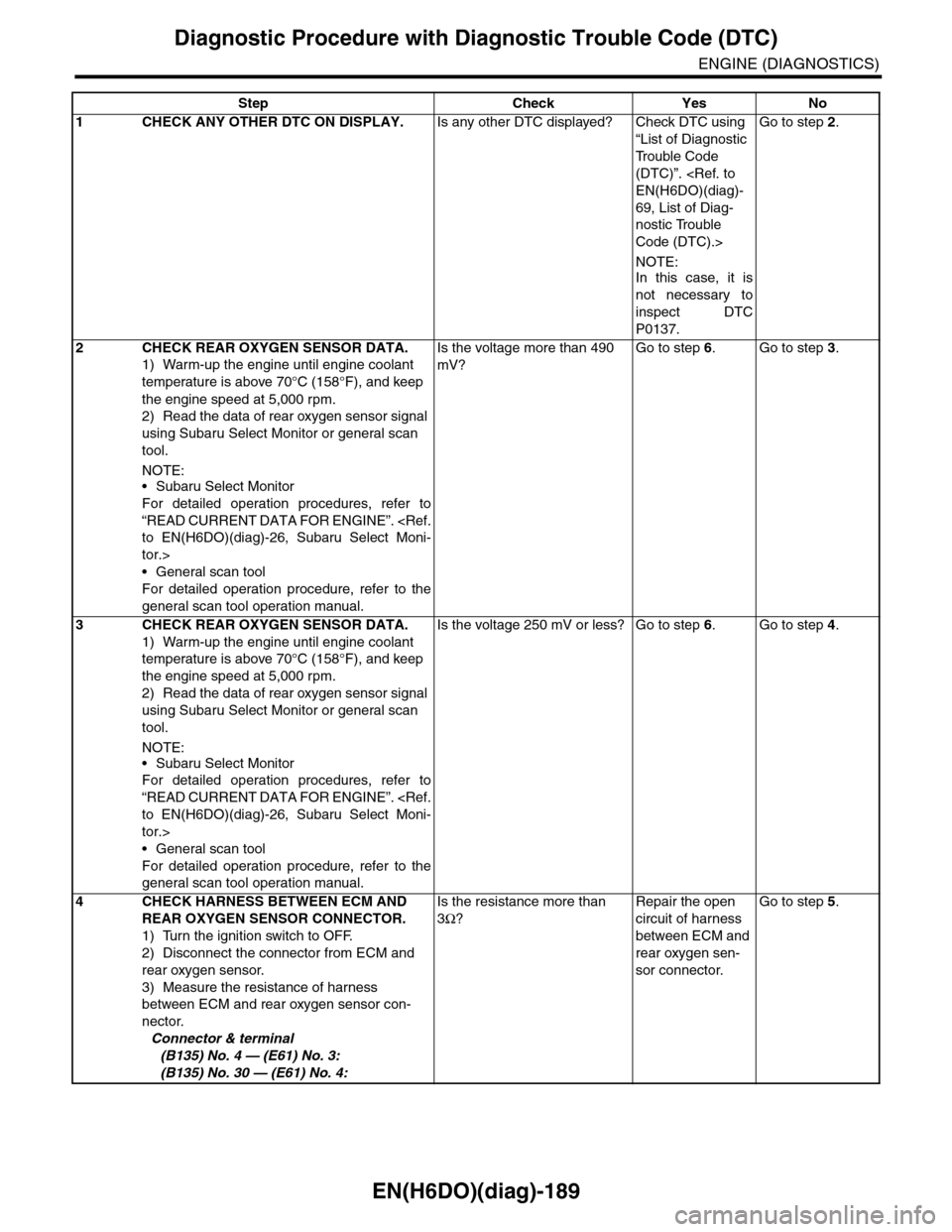
EN(H6DO)(diag)-189
Diagnostic Procedure with Diagnostic Trouble Code (DTC)
ENGINE (DIAGNOSTICS)
Step Check Yes No
1CHECK ANY OTHER DTC ON DISPLAY.Is any other DTC displayed? Check DTC using
“List of Diagnostic
Tr o u b l e C o d e
(DTC)”.
69, List of Diag-
nostic Trouble
Code (DTC).>
NOTE:
In this case, it is
not necessary to
inspect DTC
P0137.
Go to step 2.
2CHECK REAR OXYGEN SENSOR DATA.
1) Warm-up the engine until engine coolant
temperature is above 70°C (158°F), and keep
the engine speed at 5,000 rpm.
2) Read the data of rear oxygen sensor signal
using Subaru Select Monitor or general scan
tool.
NOTE:•Subaru Select Monitor
For detailed operation procedures, refer to
“READ CURRENT DATA FOR ENGINE”.
tor.>
•General scan tool
For detailed operation procedure, refer to the
general scan tool operation manual.
Is the voltage more than 490
mV?
Go to step 6.Go to step 3.
3CHECK REAR OXYGEN SENSOR DATA.
1) Warm-up the engine until engine coolant
temperature is above 70°C (158°F), and keep
the engine speed at 5,000 rpm.
2) Read the data of rear oxygen sensor signal
using Subaru Select Monitor or general scan
tool.
NOTE:
•Subaru Select Monitor
For detailed operation procedures, refer to
“READ CURRENT DATA FOR ENGINE”.
tor.>
•General scan tool
For detailed operation procedure, refer to the
general scan tool operation manual.
Is the voltage 250 mV or less? Go to step 6.Go to step 4.
4CHECK HARNESS BETWEEN ECM AND
REAR OXYGEN SENSOR CONNECTOR.
1) Turn the ignition switch to OFF.
2) Disconnect the connector from ECM and
rear oxygen sensor.
3) Measure the resistance of harness
between ECM and rear oxygen sensor con-
nector.
Connector & terminal
(B135) No. 4 — (E61) No. 3:
(B135) No. 30 — (E61) No. 4:
Is the resistance more than
3Ω?
Repair the open
circuit of harness
between ECM and
rear oxygen sen-
sor connector.
Go to step 5.
Page 1366 of 2453
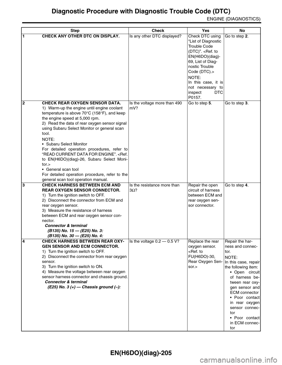
EN(H6DO)(diag)-205
Diagnostic Procedure with Diagnostic Trouble Code (DTC)
ENGINE (DIAGNOSTICS)
Step Check Yes No
1CHECK ANY OTHER DTC ON DISPLAY.Is any other DTC displayed? Check DTC using
“List of Diagnostic
Tr o u b l e C o d e
(DTC)”.
69, List of Diag-
nostic Trouble
Code (DTC).>
NOTE:
In this case, it is
not necessary to
inspect DTC
P0157.
Go to step 2.
2CHECK REAR OXYGEN SENSOR DATA.
1) Warm-up the engine until engine coolant
temperature is above 70°C (158°F), and keep
the engine speed at 5,000 rpm.
2) Read the data of rear oxygen sensor signal
using Subaru Select Monitor or general scan
tool.
NOTE:•Subaru Select Monitor
For detailed operation procedures, refer to
“READ CURRENT DATA FOR ENGINE”.
tor.>
•General scan tool
For detailed operation procedure, refer to the
general scan tool operation manual.
Is the voltage more than 490
mV?
Go to step 5.Go to step 3.
3CHECK HARNESS BETWEEN ECM AND
REAR OXYGEN SENSOR CONNECTOR.
1) Turn the ignition switch to OFF.
2) Disconnect the connector from ECM and
rear oxygen sensor.
3) Measure the resistance of harness
between ECM and rear oxygen sensor con-
nector.
Connector & terminal
(B135) No. 15 — (E25) No. 3:
(B135) No. 30 — (E25) No. 4:
Is the resistance more than
3Ω?
Repair the open
circuit of harness
between ECM and
rear oxygen sen-
sor connector.
Go to step 4.
4CHECK HARNESS BETWEEN REAR OXY-
GEN SENSOR AND ECM CONNECTOR.
1) Turn the ignition switch to OFF.
2) Disconnect the connector from rear oxygen
sensor.
3) Turn the ignition switch to ON.
4) Measure the voltage between rear oxygen
sensor harness connector and chassis ground.
Connector & terminal
(E25) No. 3 (+) — Chassis ground (–):
Is the voltage 0.2 — 0.5 V? Replace the rear
oxygen sensor.
Rear Oxygen Sen-
sor.>
Repair the har-
ness and connec-
tor.
NOTE:
In this case, repair
the following item:
•Open circuit
of harness be-
tween rear oxy-
gen sensor and
ECM connector
•Poor contact
in rear oxygen
sensor connec-
tor
•Poor contact
in ECM connec-
tor
Page 1370 of 2453
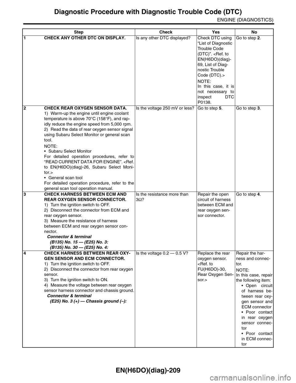
EN(H6DO)(diag)-209
Diagnostic Procedure with Diagnostic Trouble Code (DTC)
ENGINE (DIAGNOSTICS)
Step Check Yes No
1CHECK ANY OTHER DTC ON DISPLAY.Is any other DTC displayed? Check DTC using
“List of Diagnostic
Tr o u b l e C o d e
(DTC)”.
69, List of Diag-
nostic Trouble
Code (DTC).>
NOTE:
In this case, it is
not necessary to
inspect DTC
P0138.
Go to step 2.
2CHECK REAR OXYGEN SENSOR DATA.
1) Warm-up the engine until engine coolant
temperature is above 70°C (158°F), and rap-
idly reduce the engine speed from 5,000 rpm.
2) Read the data of rear oxygen sensor signal
using Subaru Select Monitor or general scan
tool.
NOTE:•Subaru Select Monitor
For detailed operation procedures, refer to
“READ CURRENT DATA FOR ENGINE”.
tor.>
•General scan tool
For detailed operation procedure, refer to the
general scan tool operation manual.
Is the voltage 250 mV or less? Go to step 5.Go to step 3.
3CHECK HARNESS BETWEEN ECM AND
REAR OXYGEN SENSOR CONNECTOR.
1) Turn the ignition switch to OFF.
2) Disconnect the connector from ECM and
rear oxygen sensor.
3) Measure the resistance of harness
between ECM and rear oxygen sensor con-
nector.
Connector & terminal
(B135) No. 15 — (E25) No. 3:
(B135) No. 30 — (E25) No. 4:
Is the resistance more than
3Ω?
Repair the open
circuit of harness
between ECM and
rear oxygen sen-
sor connector.
Go to step 4.
4CHECK HARNESS BETWEEN REAR OXY-
GEN SENSOR AND ECM CONNECTOR.
1) Turn the ignition switch to OFF.
2) Disconnect the connector from rear oxygen
sensor.
3) Turn the ignition switch to ON.
4) Measure the voltage between rear oxygen
sensor harness connector and chassis ground.
Connector & terminal
(E25) No. 3 (+) — Chassis ground (–):
Is the voltage 0.2 — 0.5 V? Replace the rear
oxygen sensor.
Rear Oxygen Sen-
sor.>
Repair the har-
ness and connec-
tor.
NOTE:
In this case, repair
the following item:
•Open circuit
of harness be-
tween rear oxy-
gen sensor and
ECM connector
•Poor contact
in rear oxygen
sensor connec-
tor
•Poor contact
in ECM connec-
tor