ignition coil SUBARU TRIBECA 2009 1.G Service User Guide
[x] Cancel search | Manufacturer: SUBARU, Model Year: 2009, Model line: TRIBECA, Model: SUBARU TRIBECA 2009 1.GPages: 2453, PDF Size: 46.32 MB
Page 1837 of 2453
IG(H6DO)-2
General Description
IGNITION
1. General Description
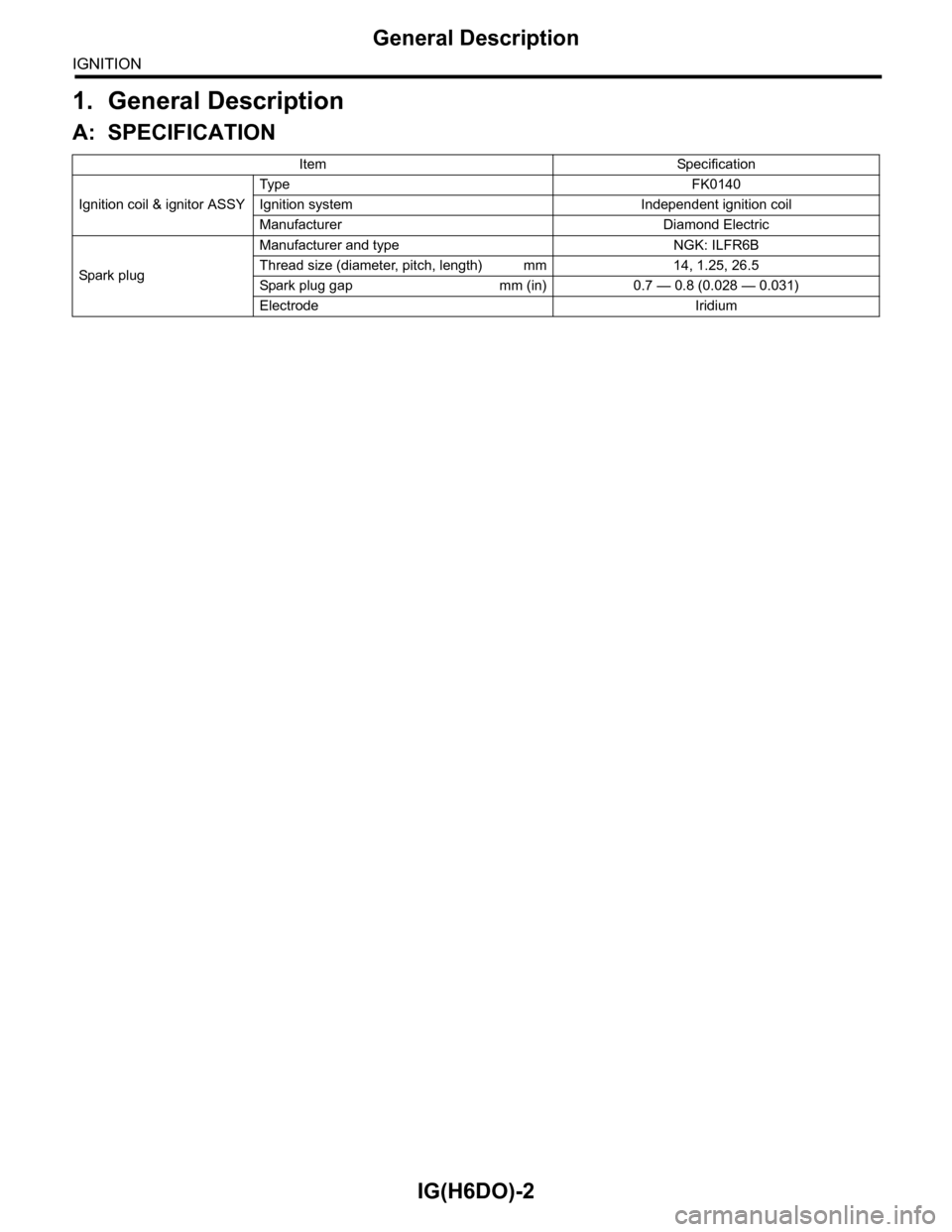
A: SPECIFICATION
Item Specification
Ignition coil & ignitor ASSY
Typ e F K 0 14 0
Ignition system Independent ignition coil
Manufacturer Diamond Electric
Spar k p l ug
Manufacturer and type NGK: ILFR6B
Thread size (diameter, pitch, length) mm 14, 1.25, 26.5
Spark plug gap mm (in) 0.7 — 0.8 (0.028 — 0.031)
Electrode Iridium
Page 1838 of 2453
IG(H6DO)-3
General Description
IGNITION
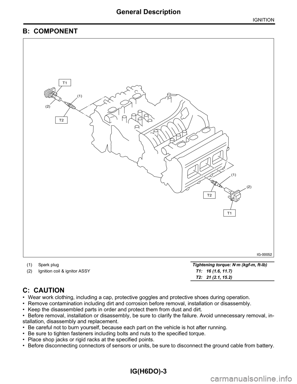
B: COMPONENT
C: CAUTION
•Wear work clothing, including a cap, protective goggles and protective shoes during operation.
•Remove contamination including dirt and corrosion before removal, installation or disassembly.
•Keep the disassembled parts in order and protect them from dust and dirt.
•Before removal, installation or disassembly, be sure to clarify the failure. Avoid unnecessary removal, in-
stallation, disassembly and replacement.
•Be careful not to burn yourself, because each part on the vehicle is hot after running.
•Be sure to tighten fasteners including bolts and nuts to the specified torque.
•Place shop jacks or rigid racks at the specified points.
•Before disconnecting connectors of sensors or units, be sure to disconnect the ground cable from battery.
(1) Spark plug Tightening torque: N·m (kgf-m, ft-lb)
(2) Ignition coil & ignitor ASSY T1: 16 (1.6, 11.7)
T2: 21 (2.1, 15.2)
IG-00052
(1)
(1)
(2)
(2)
T1
T2
T2
T1
Page 1839 of 2453
IG(H6DO)-4
Spark Plug
IGNITION
2. Spark Plug
A: REMOVAL
CAUTION:
All spark plugs installed on an engine must be
of the same heat range.
Spark plug:
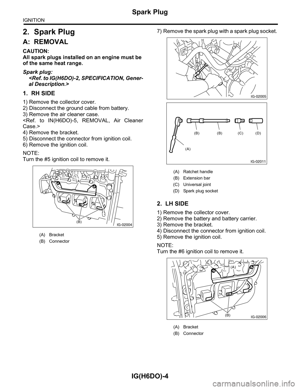
1. RH SIDE
1) Remove the collector cover.
2) Disconnect the ground cable from battery.
3) Remove the air cleaner case.
4) Remove the bracket.
5) Disconnect the connector from ignition coil.
6) Remove the ignition coil.
NOTE:
Turn the #5 ignition coil to remove it.
7) Remove the spark plug with a spark plug socket.
2. LH SIDE
1) Remove the collector cover.
2) Remove the battery and battery carrier.
3) Remove the bracket.
4) Disconnect the connector from ignition coil.
5) Remove the ignition coil.
NOTE:
Turn the #6 ignition coil to remove it.
(A) Bracket
(B) Connector
IG-02004(B)
(A)
(A) Ratchet handle
(B) Extension bar
(C) Universal joint
(D) Spark plug socket
(A) Bracket
(B) Connector
IG-02005
(D)(C)(B)(B)
(A)
IG-02011
IG-02006
(A)
(B)
Page 1840 of 2453
IG(H6DO)-5
Spark Plug
IGNITION
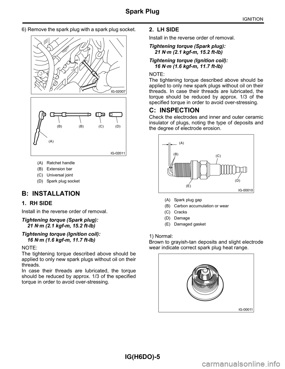
6) Remove the spark plug with a spark plug socket.
B: INSTALLATION
1. RH SIDE
Install in the reverse order of removal.
Tightening torque (Spark plug):
21 N·m (2.1 kgf-m, 15.2 ft-lb)
Tightening torque (Ignition coil):
16 N·m (1.6 kgf-m, 11.7 ft-lb)
NOTE:
The tightening torque described above should be
applied to only new spark plugs without oil on their
threads.
In case their threads are lubricated, the torque
should be reduced by approx. 1/3 of the specified
torque in order to avoid over-stressing.
2. LH SIDE
Install in the reverse order of removal.
Tightening torque (Spark plug):
21 N·m (2.1 kgf-m, 15.2 ft-lb)
Tightening torque (Ignition coil):
16 N·m (1.6 kgf-m, 11.7 ft-lb)
NOTE:
The tightening torque described above should be
applied to only new spark plugs without oil on their
threads. In case their threads are lubricated, the
torque should be reduced by approx. 1/3 of the
specified torque in order to avoid over-stressing.
C: INSPECTION
Check the electrodes and inner and outer ceramic
insulator of plugs, noting the type of deposits and
the degree of electrode erosion.
1) Normal:
Brown to grayish-tan deposits and slight electrode
wear indicate correct spark plug heat range.
(A) Ratchet handle
(B) Extension bar
(C) Universal joint
(D) Spark plug socket
IG-02007
(D)(C)(B)(B)
(A)
IG-02011
(A) Spark plug gap
(B) Carbon accumulation or wear
(C) Cracks
(D) Damage
(E) Damaged gasket
IG-00010
(A)
(B)(C)
(D)
(E)
IG-00011
Page 1842 of 2453
IG(H6DO)-7
Ignition Coil & Ignitor Assembly
IGNITION
3. Ignition Coil & Ignitor Assem-
bly
A: REMOVAL
Direct ignition type has been adopted. Refer to
“Spark Plug” for removal procedure.
B: INSTALLATION
Install in the reverse order of removal.
Tightening torque:
16 N·m (1.6 kgf-m, 11.7 ft-lb)
C: INSPECTION
For inspection procedure, refer to “Diagnostics for
Engine Starting Failure.”
for Engine Starting Failure.>
Page 1843 of 2453
IG(H6DO)-8
Ignition Coil & Ignitor Assembly
IGNITION
Page 1893 of 2453
ME(H6DO)-27
Valve Clearance
MECHANICAL
8. Valve Clearance
A: INSPECTION
Inspection and adjustment of valve clearance
should be performed while engine is cold.
1) Set the vehicle on a lift.
2) Remove the collector cover.
3) Disconnect the ground cable from battery.
4) Lift-up the vehicle.
5) Remove the under cover.
6) Lower the vehicle.
7) When inspecting RH side cylinders:
(1) Remove the air intake duct and air cleaner
case.
(2) Remove the fuel tank protector (RH).
(3) Disconnect the connector of oil pressure
switch.
(4) Remove the ignition coil.
Assembly.>
(5) Remove the rocker cover (RH).
8) When inspecting LH side cylinders:
(1) Disconnect the battery cable, and then re-
move the battery and battery carrier.
(2) Disconnect the PCV hose and blow-by hose
from rocker cover (LH).
(3) Remove the fuel pipe protector (LH).
(4) Remove the ignition coil.
Assembly.>
(5) Remove the rocker cover (LH).
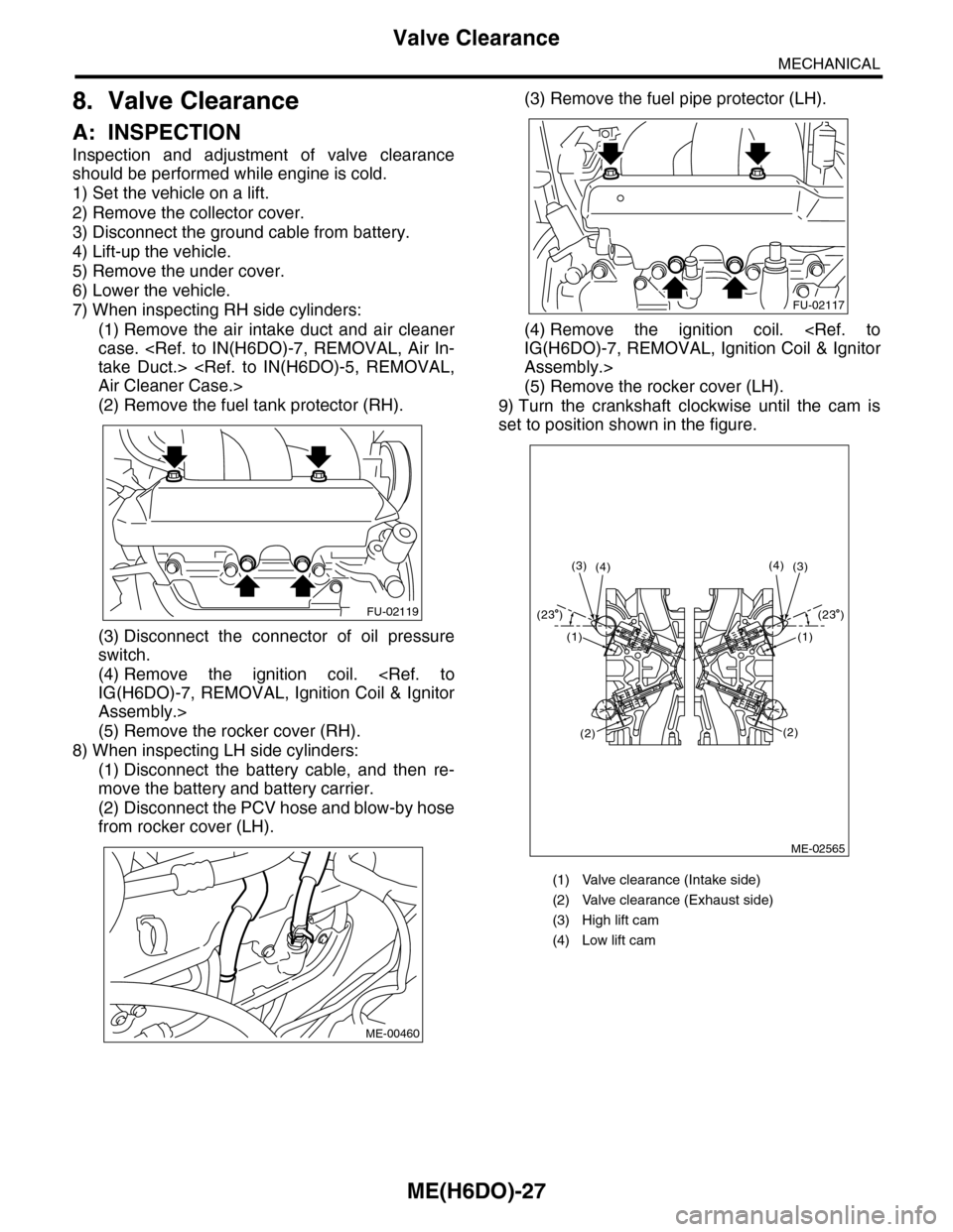
9) Turn the crankshaft clockwise until the cam is
set to position shown in the figure.
FU-02119
ME-00460
(1) Valve clearance (Intake side)
(2) Valve clearance (Exhaust side)
(3) High lift cam
(4) Low lift cam
FU-02117
ME-02565
(4)(3)(3)(4)
(1)
(2)
(1)
(2)
(23 )(23 )
Page 1992 of 2453
PM-9
Spark Plug
PERIODIC MAINTENANCE SERVICES
5. Spark Plug
A: REPLACEMENT
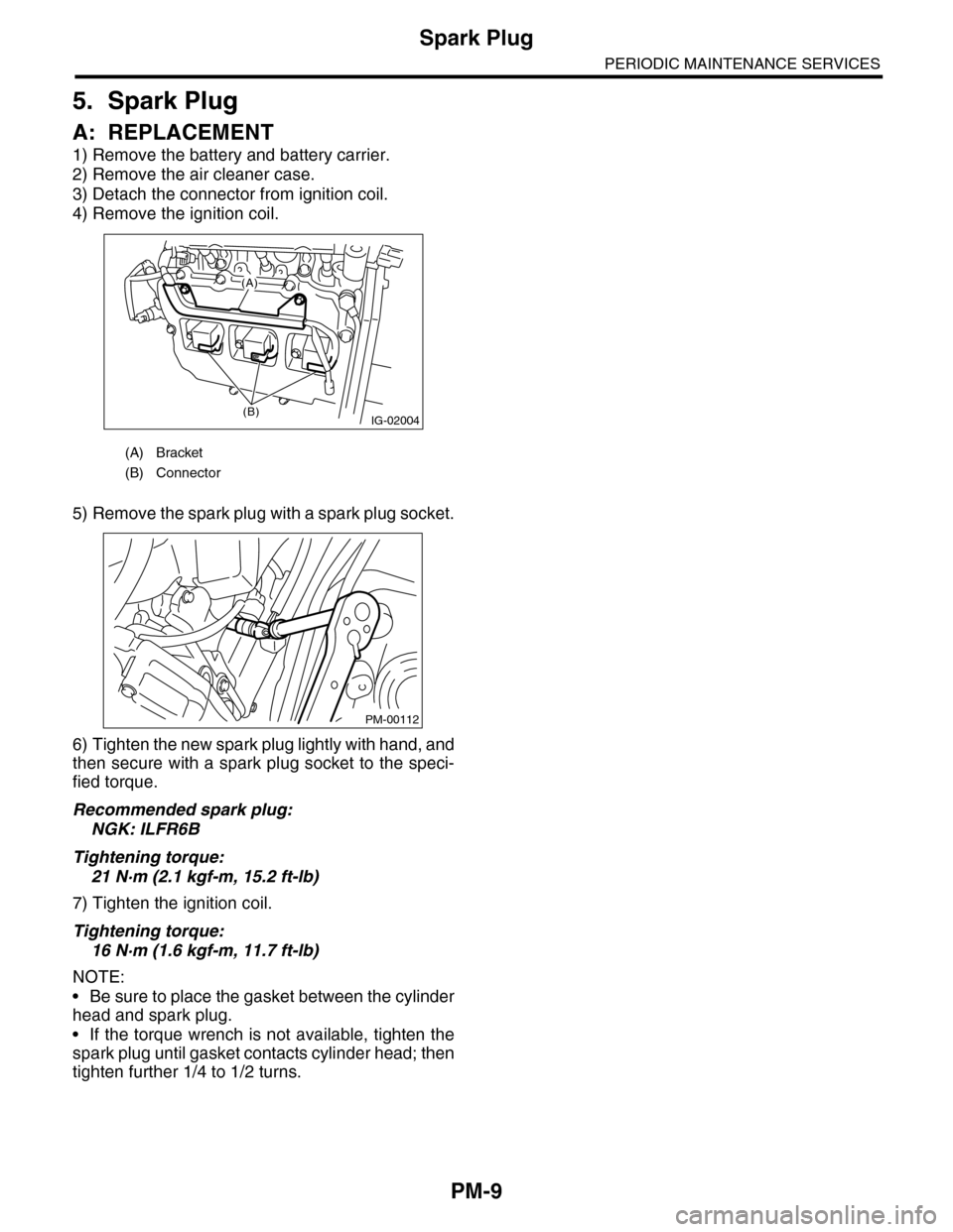
1) Remove the battery and battery carrier.
2) Remove the air cleaner case.
3) Detach the connector from ignition coil.
4) Remove the ignition coil.
5) Remove the spark plug with a spark plug socket.
6) Tighten the new spark plug lightly with hand, and
then secure with a spark plug socket to the speci-
fied torque.
Recommended spark plug:
NGK: ILFR6B
Tightening torque:
21 N·m (2.1 kgf-m, 15.2 ft-lb)
7) Tighten the ignition coil.
Tightening torque:
16 N·m (1.6 kgf-m, 11.7 ft-lb)
NOTE:
•Be sure to place the gasket between the cylinder
head and spark plug.
•If the torque wrench is not available, tighten the
spark plug until gasket contacts cylinder head; then
tighten further 1/4 to 1/2 turns.
(A) Bracket
(B) Connector
IG-02004(B)
(A)
PM-00112
Page 2314 of 2453
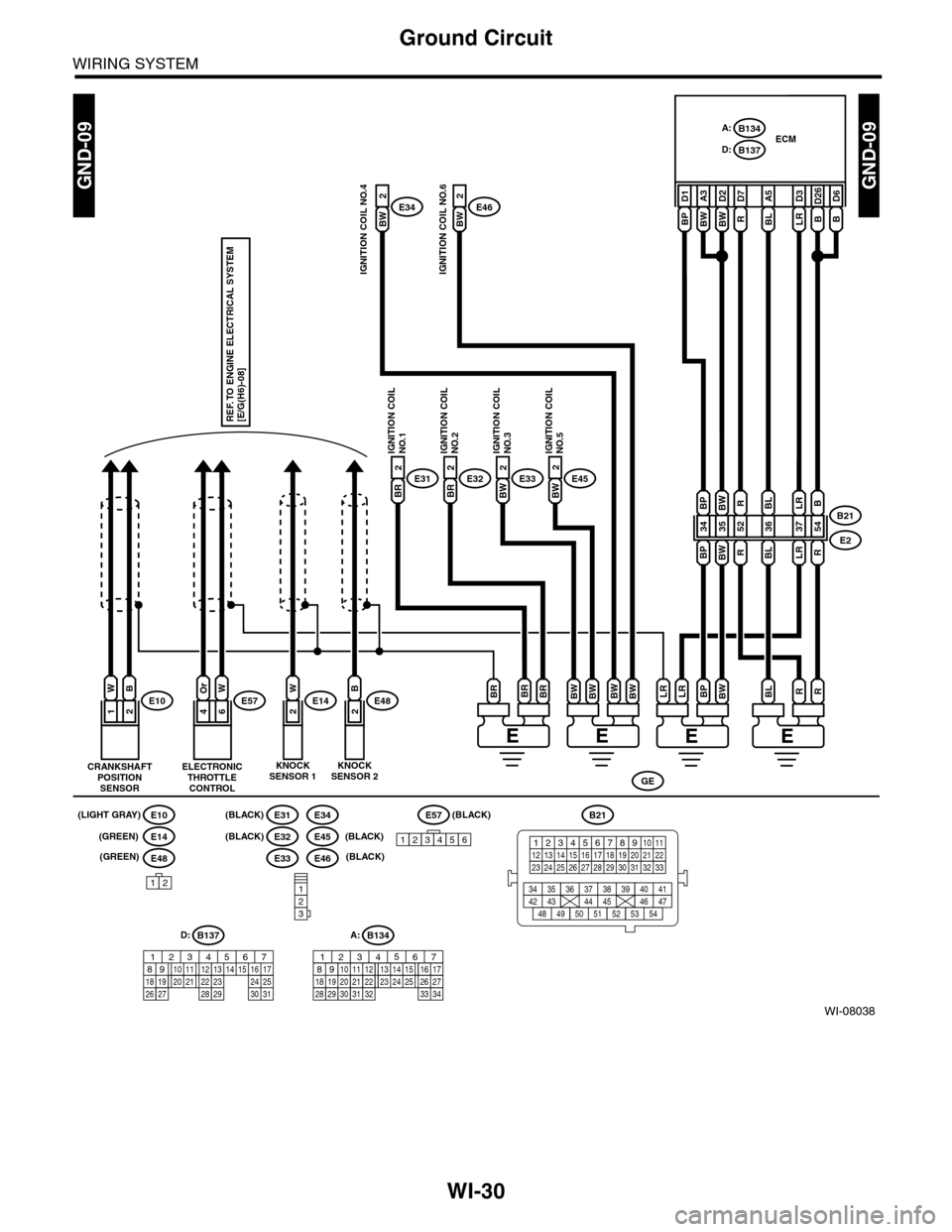
WI-30
Ground Circuit
WIRING SYSTEM
WI-08038
GND-09GND-09
BL A5B D26B
D6
R 54
BW
LR 37
LR
BL 36
BL
BW 35
BW
BP 34
BPBB21
E2
E452
LR D3BP D1BW A3BW
D2
(BLACK)
(GREEN)
(GREEN)
B134A:
B137D:ECM
BW
E332
BRE322
BRE312
IGNITION COILNO.1IGNITION COILNO.2IGNITION COILNO.3IGNITION COILNO.5
E57
ELECTRONICTHROTTLECONTROL
46
OrWE10
CRANKSHAFTPOSITIONSENSOR
12
WBE14
KNOCKSENSOR 1
2
WE482
B
12
D: A:B137
85610 11 12 13 14 157213416
3019 20 2228 29
91718 2521 23 243126 27
B134
85610 11 12 13 14 157213416
3019 20 2228 29
91718252123 24323126 2733 34
RBLBWBPLRLRBRBR
REF. TO ENGINE ELECTRICAL SYSTEM[E/G(H6)-08]
E33
E31E34
E32
E48
E10
E14
B21
12345678910 1112 13 14 15 16 17 18 19 20 21 2223 24 25 26 27 28 29 30 31 32 33
34 3542 4336 3738 39
48 4950 5152 5354
40 41444546 47123
E57
123456
GE
BWBWBRBWBW
BW
E462
BW
E342
R
R
52
R
R D7
IGNITION COIL NO.4IGNITION COIL NO.6
KNOCKSENSOR 2
(LIGHT GRAY) (BLACK)
(BLACK) (BLACK)
(BLACK)
E45
E46
Page 2317 of 2453
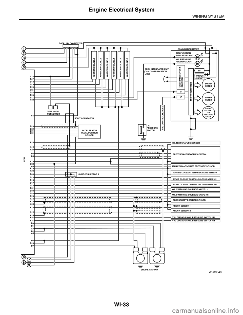
WI-33
Engine Electrical System
WIRING SYSTEM
WI-08040
A3D2
D22D23
POWERCIRCUIT
COMBINATION METER
C16B27D18D19D20D21
C11C22
C6
B23B29B31B21
1
2
3
4
5
6
ACCELERATORPEDAL POSITIONSENSOR
JOINT CONNECTOR A
JOINT CONNECTOR
MALFUNCTION INDICATOR LIGHTOIL PRESSUREWARNING LIGHT
I/F
I/F
I/F
VDC CONTROL MODULE
IGNITION COIL NO.1
BODY INTEGRATED UNIT(CAN COMMUNICATION LINE)
OILPRESSURESWITCH
CRANKSHAFT POSITION SENSORA13A14
ENGINE GROUND
ECM
A18A28
D4D5
A19B22A6A29A34
D15B30
D14D17D16D31D30
ELECTRONIC THROTTLE CONTROL
A24
A25A16
A15
A32
D1
MANIFOLD ABSOLUTE PRESSURE SENSOR
ENGINE COOLANT TEMPRERATURE SENSOR
VVL DIAGNOSIS OIL PRESSURE SWITCH RH
D25D24
KNOCK SENSOR 2
D6D26D7
A5
MICRO COMPUTER
CAN TRANSCEIVER &RECEIVER
OIL SWITCHING SOLENOID VALVE RH
TA C H O -METER
SPEEDMETER
ENGINECOOLANTTEM-PERATUREGAUGE
DATA LINK CONNECTOR
TEST MODECONNECTOR
OIL TEMPERATURE SENSORA23
A31D3
VVL DIAGNOSIS OIL PRESSURE SWITCH LH
KNOCK SENSOR 1
OIL SWITCHING SOLENOID VALVE LH
INTAKE OIL FLOW CONTROL SOLENOID VALVE RH
INTAKE OIL FLOW CONTROL SOLENOID VALVE LH
IGNITION COIL NO.2 IGNITION COIL NO.3 IGNITION COIL NO.4 IGNITION COIL NO.5 IGNITION COIL NO.6
789