width SUBARU TRIBECA 2009 1.G Service User Guide
[x] Cancel search | Manufacturer: SUBARU, Model Year: 2009, Model line: TRIBECA, Model: SUBARU TRIBECA 2009 1.GPages: 2453, PDF Size: 46.32 MB
Page 1851 of 2453

LU(H6DO)-2
General Description
LUBRICATION
1. General Description
A: SPECIFICATION
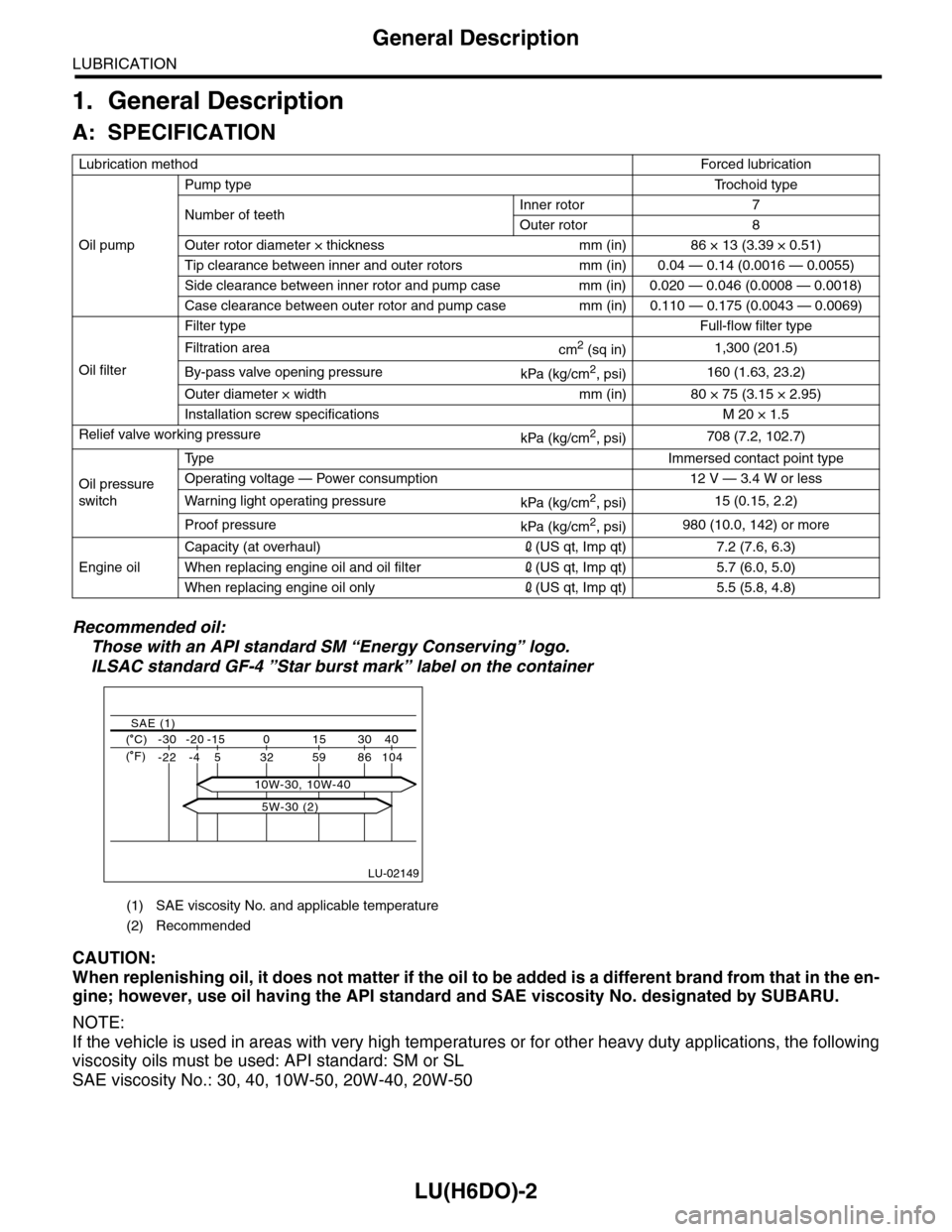
Recommended oil:
Those with an API standard SM βEnergy Conservingβ logo.
ILSAC standard GF-4 βStar burst markβ label on the container
CAUTION:
When replenishing oil, it does not matter if the oil to be added is a different brand from that in the en-
gine; however, use oil having the API standard and SAE viscosity No. designated by SUBARU.
NOTE:
If the vehicle is used in areas with very high temperatures or for other heavy duty applications, the following
viscosity oils must be used: API standard: SM or SL
SAE viscosity No.: 30, 40, 10W-50, 20W-40, 20W-50
Lubrication methodForced lubr ication
Oil pump
Pump typeTr o c h o i d t y p e
Number of teethInner rotor 7
Outer rotor 8
Outer rotor diameter Γ thickness mm (in) 86 Γ 13 (3.39 Γ 0.51)
Tip clearance between inner and outer rotors mm (in) 0.04 β 0.14 (0.0016 β 0.0055)
Side clearance between inner rotor and pump case mm (in) 0.020 β 0.046 (0.0008 β 0.0018)
Case clearance between outer rotor and pump case mm (in) 0.110 β 0.175 (0.0043 β 0.0069)
Oil filter
Filter typeFull-flow filter type
Filtration areacm2 (sq in)1,300 (201.5)
By-pass valve opening pressurekPa (kg/cm2, psi)160 (1.63, 23.2)
Outer diameter Γ width mm (in) 80 Γ 75 (3.15 Γ 2.95)
Installation screw specifications M 20 Γ 1.5
Relief valve working pressurekPa (kg/cm2, psi)708 (7.2, 102.7)
Oil pressure
switch
Ty p eImmersed contact point type
Operating voltage β Power consumption 12 V β 3.4 W or less
Wa r ni n g l ig h t o p era t i ng pr e ss ur ekPa (kg/cm2, psi)15 (0.15, 2.2)
Proof pressurekPa (kg/cm2, psi)980 (10.0, 142) or more
Engine oil
Capacity (at overhaul)2(US qt, Imp qt) 7.2 (7.6, 6.3)
When replacing engine oil and oil filter2(US qt, Imp qt) 5.7 (6.0, 5.0)
When replacing engine oil only2(US qt, Imp qt) 5.5 (5.8, 4.8)
(1) SAE viscosity No. and applicable temperature
(2) Recommended
LU-02149
( C) -30 -20 -15 0 15 30 40
-22 -4 5 32 59 86 104
SAE (1)
( F)
5W-30 (2)
10W-30, 10W-40
Page 1869 of 2453

ME(H6DO)-3
General Description
MECHANICAL
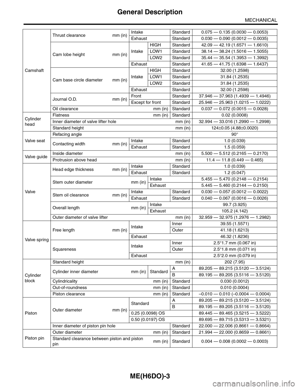
Camshaft
Thrust clearance mm (in)Intake Standard 0.075 β 0.135 (0.0030 β 0.0053)
Exhaust Standard 0.030 β 0.090 (0.0012 β 0.0035)
Cam lobe height mm (in)Intake
HIGH Standard 42.09 β 42.19 (1.6571 β 1.6610)
LOW1 Standard 38.14 β 38.24 (1.5016 β 1.5055)
LOW2 Standard 35.44 β 35.54 (1.3953 β 1.3992)
Exhaust Standard 41.65 β 41.75 (1.6398 β 1.6437)
Cam base circle diameter mm (in)Intake
HIGH Standard 32.00 (1.2598)
LOW1 Standard 31.84 (1.2535)
LOW2 Standard 31.84 (1.2535)
Exhaust Standard 32.00 (1.2598)
Journal O.D. mm (in)Fr o nt S ta n da r d 3 7. 9 46 β 3 7 . 96 3 ( 1 . 49 3 9 β 1. 4 9 46 )
Except for front Standard 25.946 β 25.963 (1.0215 β 1.0222)
Oil clearance mm (in) Standard 0.037 β 0.072 (0.0015 β 0.0028)
Cylinder
head
Flatness mm (in) Standard 0.02 (0.0008)
Inner diameter of valve lifter hole mm (in) 32.994 β 33.016 (1.2990 β 1.2998)
Standard height mm (in) 124Β±0.05 (4.88Β±0.0020)
Va l ve s e a t
Refacing angle90Β°
Contacting width mm (in)Intake Standard 1.0 (0.039)
Exhaust Standard 1.5 (0.059)
Va l ve g u i d eInside diameter mm (in) 5.500 β 5.512 (0.2165 β 0.2170)
Protrusion above head mm (in) 11.4 β 11.8 (0.449 β 0.465)
Va l ve
Head edge thickness mm (in)Intake Standard 1.0 (0.039)
Exhaust Standard 1.2 (0.047)
Stem outer diameter mm (in)Intake 5.455 β 5.470 (0.2148 β 0.2154)
Exhaust 5.445 β 5.460 (0.2144 β 0.2150)
Stem oil clearance mm (in)Intake Standard 0.030 β 0.057 (0.0012 β 0.0022)
Exhaust Standard 0.040 β 0.067 (0.0016 β 0.0026)
Overall length mm (in)Intake 99.7 (3.925)
Exhaust 105.2 (4.142)
Outer diameter of valve lifter mm (in) 32.959 β 32.975 (1.2976 β 1.2982)
Va l ve s p r i n g
Free length mm (in)IntakeInner 39.55 (1.5571)
Outer 41.18 (1.6213)
Exhaust 46.32 (1.8236)
SquarenessIntakeInner 2.5Β°1.7 mm (0.067 in)
Outer 2.5Β°1.8 mm (0.071 in)
Exhaust 2.5Β°2.0 mm (0.079 in)
Cylinder
block
Standard height mm (in) 202 (7.95)
Cylinder inner diameter mm (in) StandardA89.205 β 89.215 (3.5120 β 3.5124)
B89.195 β 89.205 (3.5116 β 3.5120)
Cylindricality mm (in) Standard 0.030 (0.0012)
Out-of-roundness mm (in) Standard 0.010 (0.0004)
Piston clearance mm (in) Standard β0.010 β 0.010 (β0.0004 β 0.0004)
PistonOuter diameter mm (in)
StandardA89.205 β 89.215 (3.5120 β 3.5124)
B89.195 β 89.205 (3.5116 β 3.5120)
0.25 (0.0098) OS 89.445 β 89.465 (3.5215 β 3.5222)
0.50 (0.0197) OS 89.695 β 89.715 (3.5313 β 3.5321)
Inner diameter of piston pin hole Standard 22.000 β 22.006 (0.8661 β 0.8664)
Piston pin
Outer diameter mm (in) Standard 21.994 β 22.000 (0.8659 β 0.8661)
Standard clearance between piston and piston
pinmm (in) Standard 0.004 β 0.008 (0.0002 β 0.0003)
Page 1925 of 2453

ME(H6DO)-59
Cylinder Head
MECHANICAL
3) Measure the flatness of the cylinder head sur-
face that mates with crankcase using a straight
edge (A) and thickness gauge (B).
Flatness:
Standard
0.02 mm (0.0008 in)
Standard height of cylinder head:
124Β±0.05 mm (4.88Β±0.0020 in)
NOTE:
Uneven torque for the cylinder head nuts can
cause warping. When reinstalling, pay special at-
tention to the torque so as to tighten evenly.
2. VALVE SEAT
Inspect the intake and exhaust valve seats, and
correct the contact surfaces with a valve seat cutter
if they are defective or when valve guides are re-
placed.
Valve seat width W:
Intake
Standard
1.0 mm (0.039 in)
Exhaust
Standard
1.5 mm (0.059 in)
3. VALVE GUIDE
1) Check the clearance between valve guide and
stem. The clearance can be checked by measuring
respectively the outer diameter of valve stem and
inner diameter of valve guide with a micrometer.
Clearance between the valve guide and valve
stem:
Standard
Intake
0.030 β 0.057 mm (0.0012 β 0.0022 in)
Exhaust
0.040 β 0.067 mm (0.0016 β 0.0026 in)
2) If the clearance between valve guide and stem
exceeds the standard, replace the valve guide or
valve itself whichever shows greater amount of
wear or damaged and etc. See the following proce-
dure for valve guide replacement.
Valve guide inner diameter:
5.500 β 5.512 mm (0.2165 β 0.2170 in
Valve stem outer diameters:
Intake
5.455 β 5.470 mm (0.2148 β 0.2154 in)
Exhaust
5.445 β 5.460 mm (0.2144 β 0.2150 in)
(1) Place the cylinder head on ST1 with the
combustion chamber upward so that valve
guides fit the holes in ST1.
(2) Insert the ST2 into valve guide and press it
down to remove the valve guide.
ST1 18250AA010 CYLINDER HEAD TABLE
ST2 499765700 VALVE GUIDE REMOVER
(A)
(B)
ME-00551
ME-00127
WME-00553
Page 2297 of 2453

WI-13
Basic Diagnostic Procedure
WIRING SYSTEM
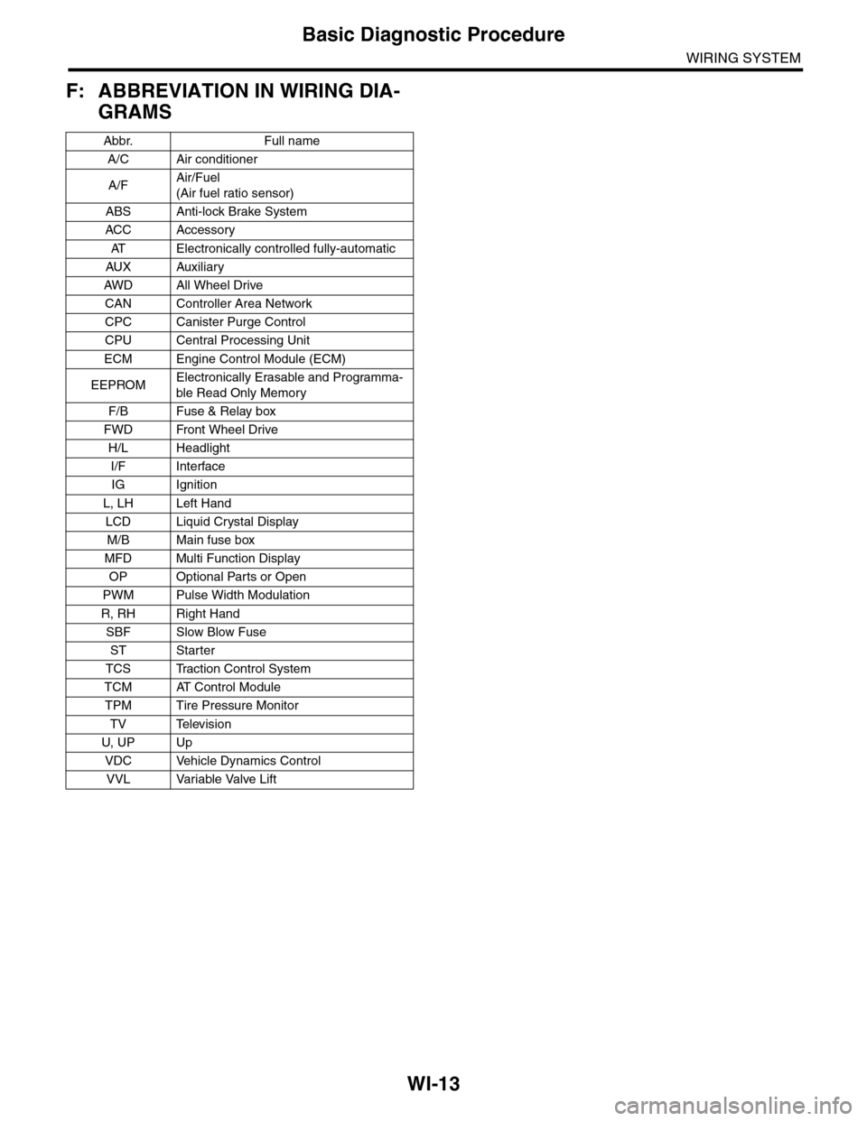
F: ABBREVIATION IN WIRING DIA-
GRAMS
Abbr. Full name
A/C Air conditioner
A/FAir/Fuel
(Air fuel ratio sensor)
ABS Anti-lock Brake System
ACC Accessor y
AT E l e c t r o n i c a l l y c o n t r o l l e d f u l l y - a u t o m a t i c
AUX Auxiliar y
AW D A ll W he e l D r i ve
CAN Controller Area Network
CPC Canister Purge Control
CPU Central Processing Unit
ECM Engine Control Module (ECM)
EEPROMElectronically Erasable and Programma-
ble Read Only Memory
F/B Fuse & Relay box
FWD Front Wheel Drive
H/L Headlight
I/F Interface
IG Ignition
L, LH Left Hand
LCD Liquid Crystal Display
M/B Main fuse box
MFD Multi Function Display
OP Optional Parts or Open
PWM Pulse Width Modulation
R, RH Right Hand
SBF Slow Blow Fuse
ST Starter
TCS Traction Control System
TCM AT Control Module
TPM Tire Pressure Monitor
TV Television
U, UP Up
VDC Vehicle Dynamics Control
VVL Variable Valve Lift