diagnostic menu SUBARU TRIBECA 2009 1.G Service Workshop Manual
[x] Cancel search | Manufacturer: SUBARU, Model Year: 2009, Model line: TRIBECA, Model: SUBARU TRIBECA 2009 1.GPages: 2453, PDF Size: 46.32 MB
Page 55 of 2453
AB(diag)-31
Subaru Select Monitor
AIRBAG SYSTEM (DIAGNOSTICS)
7. Subaru Select Monitor
A: OPERATION
1. READ DIAGNOSTIC TROUBLE CODE
(DTC)
When malfunction of airbag system occurs, the
DTC stored in airbag control module will be read
out.
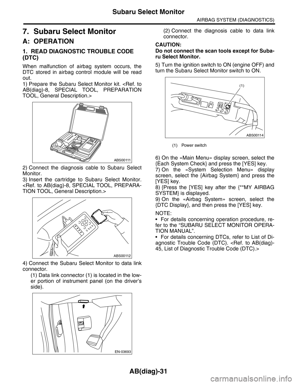
1) Prepare the Subaru Select Monitor kit.
TOOL, General Description.>
2) Connect the diagnosis cable to Subaru Select
Monitor.
3) Insert the cartridge to Subaru Select Monitor.
4) Connect the Subaru Select Monitor to data link
connector.
(1) Data link connector (1) is located in the low-
er portion of instrument panel (on the driver’s
side).
(2) Connect the diagnosis cable to data link
connector.
CAUTION:
Do not connect the scan tools except for Suba-
ru Select Monitor.
5) Turn the ignition switch to ON (engine OFF) and
turn the Subaru Select Monitor switch to ON.
6) On the «Main Menu» display screen, select the
{Each System Check} and press the [YES] key.
7) On the «System Selection Menu» display
screen, select the {Airbag System} and press the
[YES] key.
8) {Press the [YES] key after the {**MY AIRBAG
SYSTEM} is displayed.
9) On the «Airbag System» screen, select the
{DTC Display}, and then press the [YES] key.
NOTE:
•For details concerning operation procedure, re-
fer to the “SUBARU SELECT MONITOR OPERA-
TION MANUAL”.
•For details concerning DTCs, refer to List of Di-
agnostic Trouble Code (DTC).
ABS00111
ABS00112
EN-03693
(1) Power switch
ABS00114
(1)
Page 56 of 2453
AB(diag)-32
Subaru Select Monitor
AIRBAG SYSTEM (DIAGNOSTICS)
2. DISPLAY OF STATUS INFORMATION
Check the operating condition of each sensor in the event of malfunction in seat belt buckle switch and seat
position sensor, or when the seat belt buckle switch and seat position sensor has been replaced.
1) On the «Main Menu» display screen, select the {Each System Check} and press the [YES] key.
2) On the «System Selection Menu» display screen, select the {Airbag System} and press the [YES] key.
3) On the «Airbag System» display screen, select the {Status Data} and press the [YES] key.
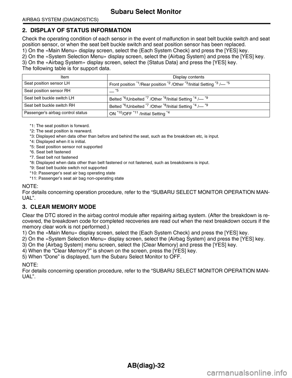
The following table is for support data.
*1: The seat position is forward.
*2: The seat position is rearward.
*3: Displayed when data other than before and behind the seat, such as the breakdown etc, is input.
*4: Displayed when it is initial.
*5: Seat position sensor not supported
*6. Seat belt fastened
*7. Seat belt not fastened
*8: Displayed when data other than belt fastened or not fastened, such as breakdowns is input.
*9: Seat belt buckle switch not supported
*10: Passenger’s seat air bag operating state
*11: Passenger’s seat air bag non-operating state
NOTE:
For details concerning operation procedure, refer to the “SUBARU SELECT MONITOR OPERATION MAN-
UAL”.
3. CLEAR MEMORY MODE
Clear the DTC stored in the airbag control module after repairing airbag system. (After the breakdown is re-
covered, the breakdown code for completed recoveries are read out when the next breakdown occurs if the
memory clear work is not performed.)
1) On the «Main Menu» display screen, select the {Each System Check} and press the [YES] key.
2) On the «System Selection Menu» display screen, select the {Airbag System} and press the [YES] key.
3) On the {Airbag System} menu screen, select the {Clear Memory} and press the [YES] key.
4) When the “Clear Memory?” is shown on the screen, press the [YES] key.
5) When “Done” is displayed, turn the Subaru Select Monitor to OFF.
NOTE:
For details concerning operation procedure, refer to the “SUBARU SELECT MONITOR OPERATION MAN-
UAL”.
Item Display contents
Seat position sensor LHFr o nt p os it i on *1/Rear position *2 /Other *3/Initial Setting *3 /–– *5
Seat position sensor RH–– *5
Seat belt buckle switch LHBelted *6/Unbelted *7 /Other *8/Initial Setting *4 /–– *9
Seat belt buckle switch RHBelted *6/Unbelted *7 /Other *8/Initial Setting *4 /–– *9
Passenger’s airbag control statusON *10/OFF *11 /Initial Setting *4
Page 175 of 2453
CC(ETC)(diag)-8
Subaru Select Monitor
CRUISE CONTROL SYSTEM (DIAGNOSTICS)
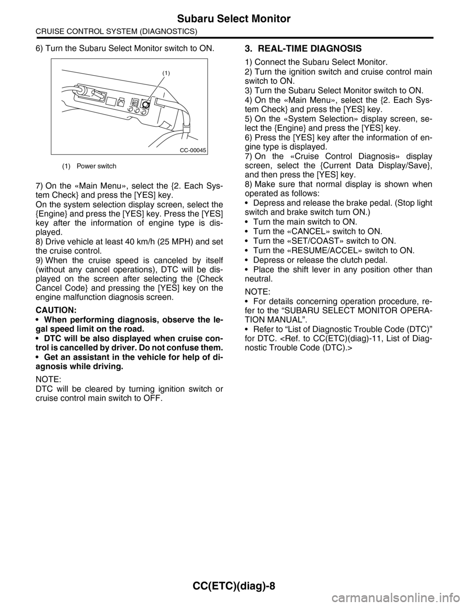
6) Turn the Subaru Select Monitor switch to ON.
7) On the «Main Menu», select the {2. Each Sys-
tem Check} and press the [YES] key.
On the system selection display screen, select the
{Engine} and press the [YES] key. Press the [YES]
key after the information of engine type is dis-
played.
8) Drive vehicle at least 40 km/h (25 MPH) and set
the cruise control.
9) When the cruise speed is canceled by itself
(without any cancel operations), DTC will be dis-
played on the screen after selecting the {Check
Cancel Code} and pressing the [YES] key on the
engine malfunction diagnosis screen.
CAUTION:
•When performing diagnosis, observe the le-
gal speed limit on the road.
•DTC will be also displayed when cruise con-
trol is cancelled by driver. Do not confuse them.
•Get an assistant in the vehicle for help of di-
agnosis while driving.
NOTE:
DTC will be cleared by turning ignition switch or
cruise control main switch to OFF.
3. REAL-TIME DIAGNOSIS
1) Connect the Subaru Select Monitor.
2) Turn the ignition switch and cruise control main
switch to ON.
3) Turn the Subaru Select Monitor switch to ON.
4) On the «Main Menu», select the {2. Each Sys-
tem Check} and press the [YES] key.
5) On the «System Selection» display screen, se-
lect the {Engine} and press the [YES] key.
6) Press the [YES] key after the information of en-
gine type is displayed.
7) On the «Cruise Control Diagnosis» display
screen, select the {Current Data Display/Save},
and then press the [YES] key.
8) Make sure that normal display is shown when
operated as follows:
•Depress and release the brake pedal. (Stop light
switch and brake switch turn ON.)
•Turn the main switch to ON.
•Turn the «CANCEL» switch to ON.
•Turn the «SET/COAST» switch to ON.
•Turn the «RESUME/ACCEL» switch to ON.
•Depress or release the clutch pedal.
•Place the shift lever in any position other than
neutral.
NOTE:
•For details concerning operation procedure, re-
fer to the “SUBARU SELECT MONITOR OPERA-
TION MANUAL”.
•Refer to “List of Diagnostic Trouble Code (DTC)”
for DTC.
(1) Power switch
CC-00045
(1)
Page 185 of 2453
CC(ETC)(diag)-18
Diagnostic Procedure with Diagnostic Trouble Code (DTC)
CRUISE CONTROL SYSTEM (DIAGNOSTICS)
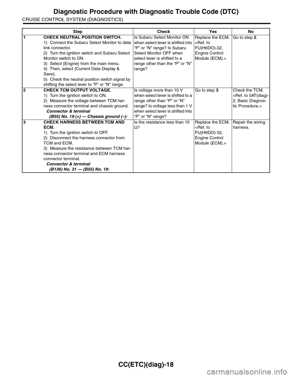
Step Check Yes No
1CHECK NEUTRAL POSITION SWITCH.
1) Connect the Subaru Select Monitor to data
link connector.
2) Turn the ignition switch and Subaru Select
Monitor switch to ON.
3) Select {Engine} from the main menu.
4) Then, select {Current Data Display &
Save}.
5) Check the neutral position switch signal by
shifting the select lever to “P” or “N” range.
Is Subaru Select Monitor ON
when select lever is shifted into
“P” or “N” range? Is Subaru
Select Monitor OFF when
select lever is shifted to a
range other than the “P” or “N”
range?
Replace the ECM.
Engine Control
Module (ECM).>
Go to step 2.
2CHECK TCM OUTPUT VOLTAGE.
1) Turn the ignition switch to ON.
2) Measure the voltage between TCM har-
ness connector terminal and chassis ground.
Connector & terminal
(B55) No. 19 (+) — Chassis ground (–):
Is voltage more than 10 V
when select lever is shifted to a
range other than “P” or “N”
range? Is voltage less than 1 V
when select lever is shifted into
“P” or “N” range?
Go to step 3.Check the TCM.
tic Procedure.>
3CHECK HARNESS BETWEEN TCM AND
ECM.
1) Turn the ignition switch to OFF.
2) Disconnect the harness connector from
TCM and ECM.
3) Measure the resistance between TCM har-
ness connector terminal and ECM harness
connector terminal.
Connector & terminal
(B136) No. 31 — (B55) No. 19:
Is the resistance less than 10
Ω?
Replace the ECM.
Engine Control
Module (ECM).>
Repair the wiring
harness.
Page 423 of 2453
IM (diag)-7
Subaru Select Monitor
IMMOBILIZER (DIAGNOSTICS)
5. Subaru Select Monitor
A: OPERATION
1. HOW TO USE SUBARU SELECT MONI-
TOR
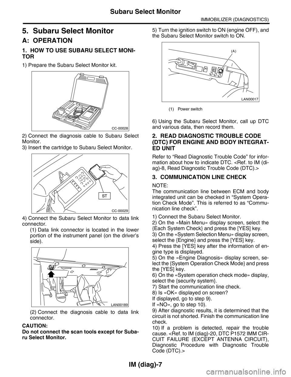
1) Prepare the Subaru Select Monitor kit.
2) Connect the diagnosis cable to Subaru Select
Monitor.
3) Insert the cartridge to Subaru Select Monitor.
4) Connect the Subaru Select Monitor to data link
connector.
(1) Data link connector is located in the lower
portion of the instrument panel (on the driver’s
side).
(2) Connect the diagnosis cable to data link
connector.
CAUTION:
Do not connect the scan tools except for Suba-
ru Select Monitor.
5) Turn the ignition switch to ON (engine OFF), and
the Subaru Select Monitor switch to ON.
6) Using the Subaru Select Monitor, call up DTC
and various data, then record them.
2. READ DIAGNOSTIC TROUBLE CODE
(DTC) FOR ENGINE AND BODY INTEGRAT-
ED UNIT
Refer to “Read Diagnostic Trouble Code” for infor-
mation about how to indicate DTC.
3. COMMUNICATION LINE CHECK
NOTE:
The communication line between ECM and body
integrated unit can be checked in “System Opera-
tion Check Mode”. This is referred to as “Commu-
nication line check”.
1) Connect the Subaru Select Monitor.
2) On the «Main Menu» display screen, select the
{Each System Check} and press the [YES] key.
3) On the «System Selection Menu» display screen,
select the {Engine} and press the [YES] key.
4) Press the [YES] key after the information of en-
gine type is displayed.
5) On the «Engine Diagnosis» display screen, se-
lect the {System Operation Check Mode} and press
the [YES] key.
6) On the «System operation check mode» display,
select the {security system}.
7) Start the communication line check.
8) Is «OK» displayed on screen?
If displayed, go to step 9).
If «NO», go to step 10).
9) After diagnostic results, it is determined that the
circuit is not shorted. Finish the communication line
check.
10) If a problem is detected, repair the trouble
cause.
Diagnostic Procedure with Diagnostic Trouble
Code (DTC).>
CC-00028
CC-00029
LAN00189
(1) Power switch
LAN00017
(A)
Page 424 of 2453
IM (diag)-8
Read Diagnostic Trouble Code (DTC)
IMMOBILIZER (DIAGNOSTICS)
6. Read Diagnostic Trouble
Code (DTC)
A: OPERATION
1. ECM
1) On the «Main Menu» display screen, select the
{Each System Check} and press the [YES] key.
2) On the «System Selection Menu» display
screen, select the {Engine} and press the [YES]
key.
3) Press the [YES] key after the information of en-
gine type is displayed.
4) On the «Engine Diagnosis» screen, select the
{DTC Display}, and then press the [YES] key.
5) On the «Diagnostic Code(s) Display» screen,
select the {Current Diagnostic Code(s)} or {History
Diagnostic Code(s)}, and then press the [YES] key.
NOTE:
•For detailed operation procedure, refer to the
“SUBARU SELECT MONITOR OPERATION
MANUAL”.
•For detailed concerning DTC, refer to the List of
DTC.
2. BODY INTEGRATED UNIT
1) On the «Main Menu» display screen, select the
{Each System Check} and press the [YES] key.
2) On the «System Selection Menu» display
screen, select the {Integ. unit mode} and press the
[YES] key.
3) Press the [YES] key after the {Integ. unit mode}
is displayed.
4) On the «Integ. unit failure diag» display screen,
select the {Diagnostic Code(s) Display} and press
the [YES] key.
NOTE:
•For detailed operation procedure, refer to the
“SUBARU SELECT MONITOR OPERATION
MANUAL”.
•For detailed concerning DTC, refer to the List of
DTC.
Page 425 of 2453
![SUBARU TRIBECA 2009 1.G Service Workshop Manual IM (diag)-9
Clear Memory Mode
IMMOBILIZER (DIAGNOSTICS)
7. Clear Memory Mode
A: OPERATION
1. ECM
1) On the «Main Menu» display screen, select the
{Each System Check} and press the [YES] key.
2) On SUBARU TRIBECA 2009 1.G Service Workshop Manual IM (diag)-9
Clear Memory Mode
IMMOBILIZER (DIAGNOSTICS)
7. Clear Memory Mode
A: OPERATION
1. ECM
1) On the «Main Menu» display screen, select the
{Each System Check} and press the [YES] key.
2) On](/img/17/7322/w960_7322-424.png)
IM (diag)-9
Clear Memory Mode
IMMOBILIZER (DIAGNOSTICS)
7. Clear Memory Mode
A: OPERATION
1. ECM
1) On the «Main Menu» display screen, select the
{Each System Check} and press the [YES] key.
2) On the «System Selection Menu» display
screen, select the {Engine} and press the [YES]
key.
3) Press the [YES] key after the information of en-
gine type is displayed.
4) On the «Engine Diagnosis» display screen, se-
lect the {Memory Clear} and press the [YES] key.
5) When the ‘Done’ are shown on the display
screen, turn the Subaru Select Monitor and ignition
switch to OFF.
NOTE:
•After the memory has been cleared, the idle air
control solenoid valve must be initialized. To exe-
cute this procedure, turn the ignition switch to ON.
Wait for 3 seconds before starting the engine.
•For detailed operation procedure, refer to the
“SUBARU SELECT MONITOR OPERATION
MANUAL”.
2. BODY INTEGRATED UNIT
1) On the «Main Menu» display screen, select the
{Each System Check} and press the [YES] key.
2) On the «System Selection Menu» display
screen, select the {Integ. unit mode} and press the
[YES] key.
3) Press the [YES] key after the {Integ. unit mode}
is displayed.
4) On the «Integ. unit mode failure diag» display
screen, select the {Clear Memory} and press the
[YES] key.
5) When the ‘Done’ are shown on the display
screen, turn the Subaru Select Monitor and ignition
switch to OFF.
NOTE:
For detailed operation procedure, refer to the
“SUBARU SELECT MONITOR OPERATION
MANUAL”.
Page 468 of 2453
LAN(diag)-12
Subaru Select Monitor
LAN SYSTEM (DIAGNOSTICS)
6. Subaru Select Monitor
A: OPERATION
1. READ DIAGNOSTIC TROUBLE CODE
(DTC)
NOTE:
•DTC is displayed in the sequence of inputting.
(When inputting two DTCs or more simultaneously,
they are displayed in the sequence of priority.)
•When more than two DTCs are displayed, per-
form the diagnosis of top of them.
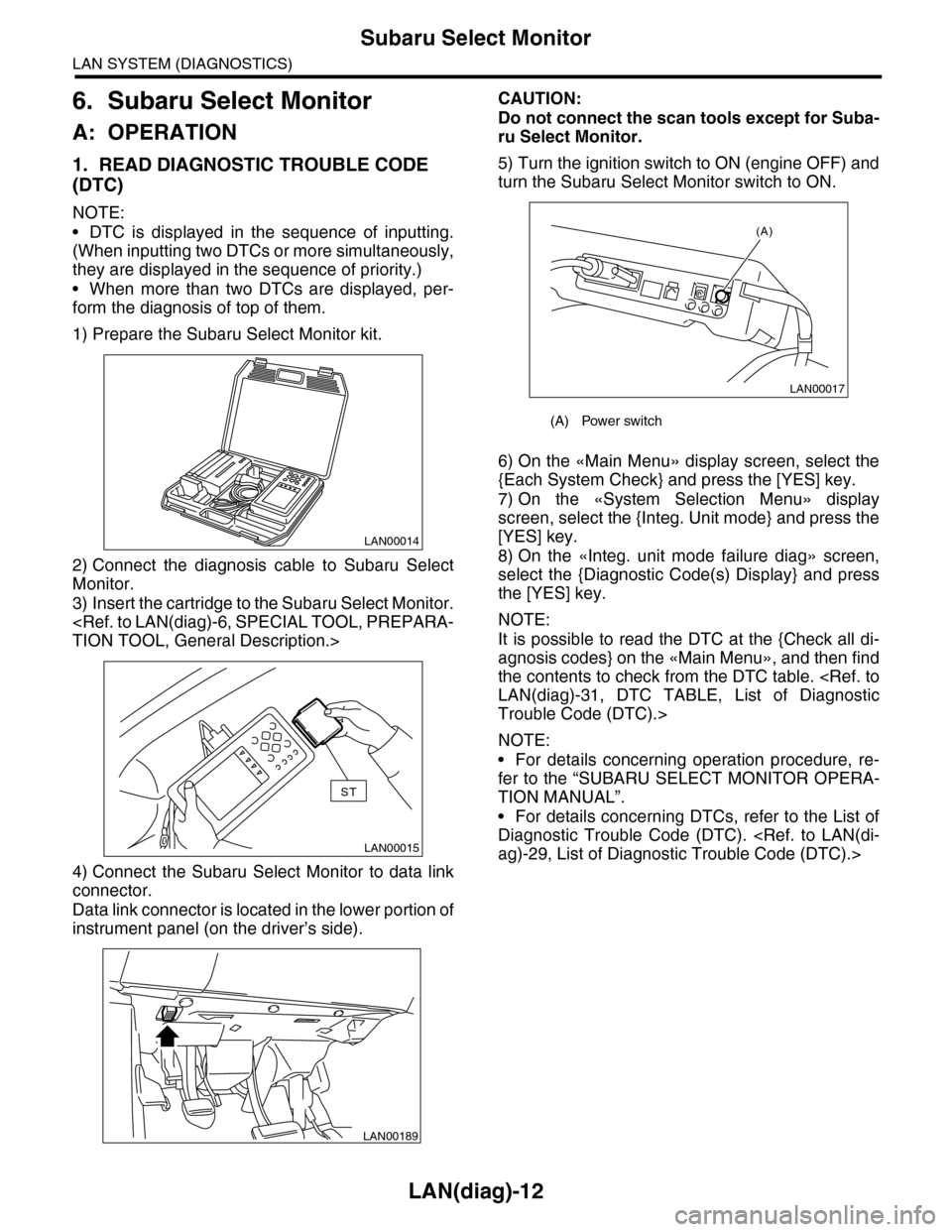
1) Prepare the Subaru Select Monitor kit.
2) Connect the diagnosis cable to Subaru Select
Monitor.
3) Insert the cartridge to the Subaru Select Monitor.
4) Connect the Subaru Select Monitor to data link
connector.
Data link connector is located in the lower portion of
instrument panel (on the driver’s side).
CAUTION:
Do not connect the scan tools except for Suba-
ru Select Monitor.
5) Turn the ignition switch to ON (engine OFF) and
turn the Subaru Select Monitor switch to ON.
6) On the «Main Menu» display screen, select the
{Each System Check} and press the [YES] key.
7) On the «System Selection Menu» display
screen, select the {Integ. Unit mode} and press the
[YES] key.
8) On the «Integ. unit mode failure diag» screen,
select the {Diagnostic Code(s) Display} and press
the [YES] key.
NOTE:
It is possible to read the DTC at the {Check all di-
agnosis codes} on the «Main Menu», and then find
the contents to check from the DTC table.
Trouble Code (DTC).>
NOTE:
•For details concerning operation procedure, re-
fer to the “SUBARU SELECT MONITOR OPERA-
TION MANUAL”.
•For details concerning DTCs, refer to the List of
Diagnostic Trouble Code (DTC).
LAN00014
LAN00015
ST
LAN00189
(A) Power switch
LAN00017
(A)
Page 469 of 2453
![SUBARU TRIBECA 2009 1.G Service Workshop Manual LAN(diag)-13
Subaru Select Monitor
LAN SYSTEM (DIAGNOSTICS)
2. READ CURRENT DATA
1) On the «Main Menu» display screen, select the {Each System Check} and press the [YES] key.
2) On the «System Sele SUBARU TRIBECA 2009 1.G Service Workshop Manual LAN(diag)-13
Subaru Select Monitor
LAN SYSTEM (DIAGNOSTICS)
2. READ CURRENT DATA
1) On the «Main Menu» display screen, select the {Each System Check} and press the [YES] key.
2) On the «System Sele](/img/17/7322/w960_7322-468.png)
LAN(diag)-13
Subaru Select Monitor
LAN SYSTEM (DIAGNOSTICS)
2. READ CURRENT DATA
1) On the «Main Menu» display screen, select the {Each System Check} and press the [YES] key.
2) On the «System Selection Menu» display screen, select the {Integ. Unit mode} and press the [YES] key.
3) On the «Integ. unit mode failure diag» display screen, select the {Current Data Display & Save} and press
the [YES] key.
4) On the «Current Data Display & Save» display screen, select the {12 Data Display} and press the [YES]
key.
5) Using the scroll key, scroll the display screen up or down until the desired data is shown.
•A support list contains both of analog and digital data, and they are shown in the following table.
3. DISPLAY OF ANALOG DATA
Items to be displayed Unit of measure Description Note
BATT Voltage (Control) 10 — 15 VBody integrated unit input
valueAlways
BATT Voltage (BACK UP) 10 — 15 VBody integrated unit input
valueAlways
IG power supply voltage 10 — 15 VBody integrated unit input
valueIgnition switch ON
ACC voltage 10 — 15 VBody integrated unit input
valueIgnition switch ACC
Illumination VR voltage 0 — 5 VBody integrated unit out-
put valueSmall light switch ON
Illumi. output d-ratio 0 — 100%Body integrated unit input
value
Small light ON
Illumination volume is other than bright.
Ambient temp sensor V 0 — 5 VBody integrated unit out-
put valueIgnition switch ON
Ambient temperature –40 — 87.5°CBody integrated unit out-
put valueIgnition switch ON
Fuel level voltage 0 — 8 VBody integrated unit input
valueIgnition switch ON
Fuel level resistance 0 — 102.3 ΩBody integrated unit input
valueIgnition switch ON
key-lock solenoid V 6 — 12 VBody integrated unit out-
put value
Other than parking range
Ignition ON
number of regist. 0 — 4 Key No. to register
Fr o nt W he e l S p ee d km / h C A N d a t a i np u t val u e R ec ep t io n f r o m V DC u ni t
VDC/ABS latest f-codeDTC display (Tempo-
rarily)CAN data input value
It is normal when DTC is not been input
even if this code is displayed.
Reception from VDC
Blower fan steps 0 — 2 levels CAN data input value0: OFF, 1: Low, 2: 2 levels or more
Reception from air conditioner ECM
Fuel level resistance2 0 — 102.3 ΩCAN data output value Reception from body integrated unit
Fuel consumption cc/s CAN data input valueReception from ECM and transmission to
center monitor
Coolant Temp. 40 — 130°C CAN data input value Reception from ECM
Ve h i c l e l a t e r a l Gm/s2CAN data input value Reception from VDC unit
SPORT Shift Stages 0 — 7 levels CAN data input value
(0: Light OFF; 1 — 5: Gear display; 6: Fail; 7:
AT F t e m p e r a t u r e H i g h / L o w )
Reception from TCM
Shift Position 0 — 7 levels CAN data input value
0: 1; 1: 2; 2: 3; 3: 4; 4: D; 5: N; 6: R; 7: P shift
position (There is no 8 input.)
Reception from TCM
Off delay timeOFF, Short, Normal,
Long
Body integrated unit set-
ting itemsCustomize setting
Auto lock time20, 30, 40, 50, 60 sec-
onds
Body integrated unit set-
ting itemsCustomize setting
Page 474 of 2453
![SUBARU TRIBECA 2009 1.G Service Workshop Manual LAN(diag)-18
Subaru Select Monitor
LAN SYSTEM (DIAGNOSTICS)
5. CONFIRMATION OF CURRENT SETTING
1) On the «Main Menu» display screen, select the {Each System Check} and press the [YES] key.
2) On the SUBARU TRIBECA 2009 1.G Service Workshop Manual LAN(diag)-18
Subaru Select Monitor
LAN SYSTEM (DIAGNOSTICS)
5. CONFIRMATION OF CURRENT SETTING
1) On the «Main Menu» display screen, select the {Each System Check} and press the [YES] key.
2) On the](/img/17/7322/w960_7322-473.png)
LAN(diag)-18
Subaru Select Monitor
LAN SYSTEM (DIAGNOSTICS)
5. CONFIRMATION OF CURRENT SETTING
1) On the «Main Menu» display screen, select the {Each System Check} and press the [YES] key.
2) On the «System Selection Menu» display screen, select the {Integ. Unit mode} and press the [YES] key.
3) On the «Integ. unit mode failure diag» display screen, select the {Current Data Display & Save} and press
the [YES] key.
4) On the «Current Data Display & Save» display screen, select the {12 Data Display} and press the [YES]
key.
5) Using the scroll key, scroll the display screen up or down until the desired data is shown.
6) Display the following item and record the settings.
Required items for new registration (Except for system not equipped)
Item Item to confirm Remarks
Key No. to register 1 2 3 4 Registered ID type
Off delay OFF Long Normal Short Setting for lighting off time
Auto-lock 60, 50 40, 30, 20 OFF Not suppor ted by Nor th Amer ican specifications (Unit sec.)
Rr defogger op. mode Normal ContinuousNormal: Off at 15 minutes of operation
Continuous: Operations from switch on to off
Wiper deicer op. mode Normal Continuous
Normal: Off at 15 minutes of operation
Continuous: Operations from switch ON to OFF, repeats ON
for 15 minutes, OFF for 2 minutes
Security Alarm Setup ON OFFON: Warning device operation possible
OFF: Warning device does not operate
Impact Sensor Setup ON OFF
ON: Impact sensor operation possible
OFF: Impact sensor does not operate
Tu r n O F F f o r v e h i c l e s n o t e q u i p p e d w i t h a n I m p a c t S e n s o r
Alarm monitor delay set-
tingON OFF
ON: Monitor after a fixed period of time from reception of the
keyless lock signal
OFF: Monitor after reception of the keyless lock signal
Lockout prevention ON OFFON: Lockout prevention operation
OFF: Lockout prevention not operated
Impact Sensor Yes No
Ye s : I m p a c t s e n s o r e q u i p p e d
No: Impact sensor not equipped
Always set to no for vehicles not equipped with the impact sen-
sor.
Siren setting Yes No
Ye s : V e h i c l e e q u i p p e d w i t h s i r e n
No: Vehicle not equipped with siren
The horn does not honk when the warning operates if the vehi-
cle not equipped with a siren is set to ‘Yes’.
Answer-back buzzer
setupON OFFON: Answer-back buzzer operation possible
OFF: Answer-back buzzer not operated
Hazard answer-back
setupON OFFON: Hazard answer-back buzzer operation possible
OFF: Hazard answer-back buzzer not operated
Automatic locking setup ON OFF Not suppor ted by Nor th Amer ican specifications
Ans.-back Buzzer Yes NoYe s : V e h i c l e e q u i p p e d w i t h a n s w e r - b a c k b u z z e r
No: Vehicle not equipped with answer-back buzzer
Auto locking Yes No Not suppor ted by Nor th Amer ican specifications
Door open warning (pre-
vention of batter y run-
out)
Ye s N o
Ye s : D o o r i n t e r l o c k e d r o o m l i g h t g o e s o f f w h e n o n f o r 1 0 m i n -
utes consecutively when door is open.
No: Room light remains illuminated until door is closed.
A/C ECM setting Yes No Model with auto A/C (Set to ‘Yes’)
P/W ECM setting Yes No Not supported by North American specifications
Center display failure Yes NoYe s : V e h i c l e e q u i p p e d w i t h M F D a n d n a v i g a t i o n d i s p l a y
No: Vehicle not equipped with MFD nor navigation display
Wiper deicer Yes NoYe s : V e h i c l e e q u i p p e d w i t h w i p e r d e i c e r
No: Vehicle not equipped with wiper deicer
Rear fog light setting Yes No Not supported by North American specifications
Fac t or y in i ti a l s et t i ng Fa ct o r y M ar ke tDo not change to the factory mode. Set to market when using
normally.