er ss displayed SUBARU TRIBECA 2009 1.G Service Workshop Manual
[x] Cancel search | Manufacturer: SUBARU, Model Year: 2009, Model line: TRIBECA, Model: SUBARU TRIBECA 2009 1.GPages: 2453, PDF Size: 46.32 MB
Page 2204 of 2453

5AT(diag)-87
Diagnostic Procedure with Diagnostic Trouble Code (DTC)
AUTOMATIC TRANSMISSION (DIAGNOSTICS)
7CHECK POOR CONTACT.
Check that there are no poor contact in TCM
connector, transmission connector and control
valve body connector.
Is there any loosing terminal,
entering foreign matter, dam-
aging connector body?
Repair the poor
contact.
Go to step 8.
8CHECK AFTER REPAIR.
1) Perform the clear memory mode.
2) Drive for a while, read the DTC, and check
that there is no faulty.
Is DTC displayed? Replace the TCM.
trol Module
(TCM).>
Per fo r m t he P 0 88 2
diagnosis.
P0882 TCM
POWER INPUT
SIGNAL LOW,
Diagnostic Proce-
dure with Diagnos-
tic Trouble Code
(DTC).>
Step Check Yes No
Page 2223 of 2453

5AT(diag)-106
Diagnostic Procedure with Diagnostic Trouble Code (DTC)
AUTOMATIC TRANSMISSION (DIAGNOSTICS)
6CHECK POOR CONTACT.
Check that there are no poor contact in TCM
connector, transmission connector and control
valve body connector.
Is there any loosing terminal,
entering foreign matter, dam-
aging connector body?
Repair the poor
contact.
Go to step 7.
7CHECK AFTER REPAIR.
1) Perform the clear memory mode.
2) Drive for a while, read the DTC, and check
that there is no faulty.
Is DTC displayed? Replace the TCM.
trol Module
(TCM).>
Te m p o r a r y p o o r
contact or open
circuit occurs.
Recheck that the
harness connec-
tor has no faulty.
Step Check Yes No
Page 2233 of 2453
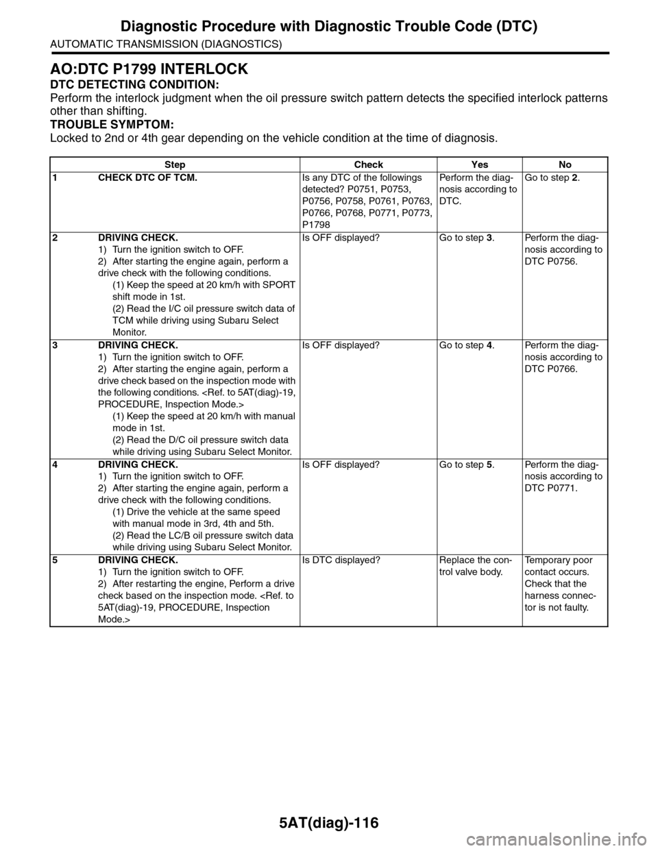
5AT(diag)-116
Diagnostic Procedure with Diagnostic Trouble Code (DTC)
AUTOMATIC TRANSMISSION (DIAGNOSTICS)
AO:DTC P1799 INTERLOCK
DTC DETECTING CONDITION:
Perform the interlock judgment when the oil pressure switch pattern detects the specified interlock patterns
other than shifting.
TROUBLE SYMPTOM:
Locked to 2nd or 4th gear depending on the vehicle condition at the time of diagnosis.
Step Check Yes No
1CHECK DTC OF TCM.Is any DTC of the followings
detected? P0751, P0753,
P0756, P0758, P0761, P0763,
P0766, P0768, P0771, P0773,
P1798
Pe r for m t h e d ia g -
nosis according to
DTC.
Go to step 2.
2DRIVING CHECK.
1) Turn the ignition switch to OFF.
2) After starting the engine again, perform a
drive check with the following conditions.
(1) Keep the speed at 20 km/h with SPORT
shift mode in 1st.
(2) Read the I/C oil pressure switch data of
TCM while driving using Subaru Select
Monitor.
Is OFF displayed? Go to step 3.Perform the diag-
nosis according to
DTC P0756.
3DRIVING CHECK.
1) Turn the ignition switch to OFF.
2) After starting the engine again, perform a
drive check based on the inspection mode with
the following conditions.
(1) Keep the speed at 20 km/h with manual
mode in 1st.
(2) Read the D/C oil pressure switch data
while driving using Subaru Select Monitor.
Is OFF displayed? Go to step 4.Perform the diag-
nosis according to
DTC P0766.
4DRIVING CHECK.
1) Turn the ignition switch to OFF.
2) After starting the engine again, perform a
drive check with the following conditions.
(1) Drive the vehicle at the same speed
with manual mode in 3rd, 4th and 5th.
(2) Read the LC/B oil pressure switch data
while driving using Subaru Select Monitor.
Is OFF displayed? Go to step 5.Perform the diag-
nosis according to
DTC P0771.
5DRIVING CHECK.
1) Turn the ignition switch to OFF.
2) After restarting the engine, Perform a drive
check based on the inspection mode.
Mode.>
Is DTC displayed? Replace the con-
trol valve body.
Te m p o r a r y p o o r
contact occurs.
Check that the
harness connec-
tor is not faulty.
Page 2235 of 2453
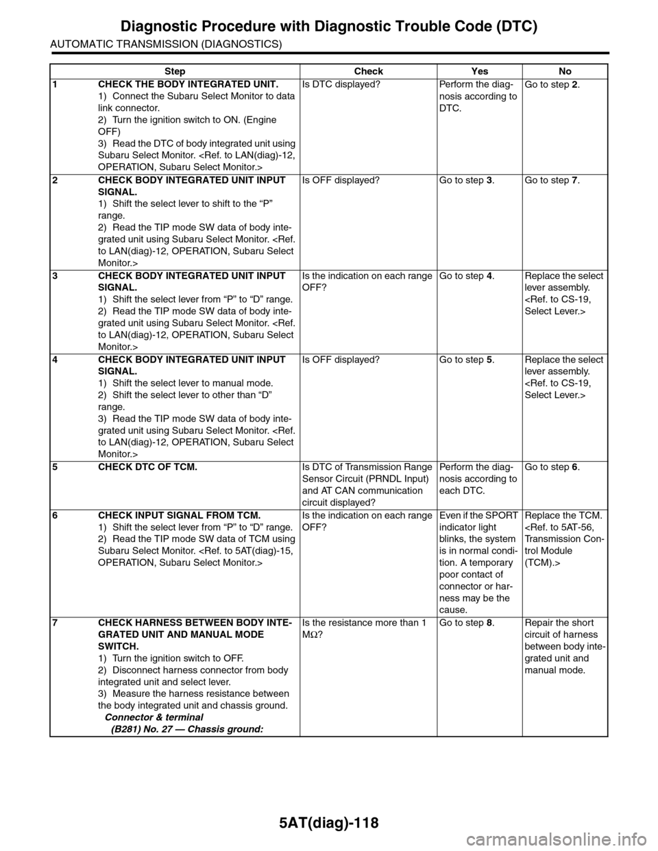
5AT(diag)-118
Diagnostic Procedure with Diagnostic Trouble Code (DTC)
AUTOMATIC TRANSMISSION (DIAGNOSTICS)
Step Check Yes No
1CHECK THE BODY INTEGRATED UNIT.
1) Connect the Subaru Select Monitor to data
link connector.
2) Turn the ignition switch to ON. (Engine
OFF)
3) Read the DTC of body integrated unit using
Subaru Select Monitor.
Is DTC displayed? Perform the diag-
nosis according to
DTC.
Go to step 2.
2CHECK BODY INTEGRATED UNIT INPUT
SIGNAL.
1) Shift the select lever to shift to the “P”
range.
2) Read the TIP mode SW data of body inte-
grated unit using Subaru Select Monitor.
Monitor.>
Is OFF displayed? Go to step 3.Go to step 7.
3CHECK BODY INTEGRATED UNIT INPUT
SIGNAL.
1) Shift the select lever from “P” to “D” range.
2) Read the TIP mode SW data of body inte-
grated unit using Subaru Select Monitor.
Monitor.>
Is the indication on each range
OFF?
Go to step 4.Replace the select
lever assembly.
4CHECK BODY INTEGRATED UNIT INPUT
SIGNAL.
1) Shift the select lever to manual mode.
2) Shift the select lever to other than “D”
range.
3) Read the TIP mode SW data of body inte-
grated unit using Subaru Select Monitor.
Monitor.>
Is OFF displayed? Go to step 5.Replace the select
lever assembly.
5CHECK DTC OF TCM.Is DTC of Transmission Range
Sensor Circuit (PRNDL Input)
and AT CAN communication
circuit displayed?
Pe r for m t h e d ia g -
nosis according to
each DTC.
Go to step 6.
6CHECK INPUT SIGNAL FROM TCM.
1) Shift the select lever from “P” to “D” range.
2) Read the TIP mode SW data of TCM using
Subaru Select Monitor.
Is the indication on each range
OFF?
Even if the SPORT
indicator light
blinks, the system
is in normal condi-
tion. A temporary
poor contact of
connector or har-
ness may be the
cause.
Replace the TCM.
trol Module
(TCM).>
7CHECK HARNESS BETWEEN BODY INTE-
GRATED UNIT AND MANUAL MODE
SWITCH.
1) Turn the ignition switch to OFF.
2) Disconnect harness connector from body
integrated unit and select lever.
3) Measure the harness resistance between
the body integrated unit and chassis ground.
Connector & terminal
(B281) No. 27 — Chassis ground:
Is the resistance more than 1
MΩ?
Go to step 8.Repair the short
circuit of harness
between body inte-
grated unit and
manual mode.
Page 2238 of 2453

5AT(diag)-121
Diagnostic Procedure without Diagnostic Trouble Code (DTC)
AUTOMATIC TRANSMISSION (DIAGNOSTICS)
Step Check Yes No
1CHECK UP/DOWN SWITCH.
1) Move the select lever to manual mode.
2) Shift and hold the select lever to up side.
3) Read the “Up Switch” data of TCM using
Subaru Select Monitor.
Is ON displayed? Go to step 2.Go to step 3.
2CHECK UP/DOWN SWITCH.
1) Move the select lever to manual mode.
2) Shift and hold the select lever to down side.
3) Read the “Down Switch” data of TCM using
Subaru Select Monitor.
Is ON displayed? Go to the proce-
dure for “CHECK
RANGE POSI-
TION/GEAR
POSITION INDI-
CATOR LIGHT”.
RANGE POSI-
TION/GEAR
POSITION INDI-
CATOR LIGHT,
Diagnostic Proce-
dure without Diag-
nostic Trouble
Code (DTC).>
Go to step 12.
3CHECK THE BODY INTEGRATED UNIT.
1) Turn the ignition switch to ON.
2) Shift and hold the select lever to up side.
3) Read the “TIP UP SW” data of body inte-
grated unit using Subaru Select Monitor.
Is ON displayed? Go to step 4.Go to step 5.
4CHECK THE BODY INTEGRATED UNIT.
Check DTC of body integrated unit.
Is DTC of CAN communication
displayed?
Pe r for m t h e d ia g -
nosis according to
DTC.
Check the TCM.
5CHECK UP/DOWN SWITCH GROUND CIR-
CUIT.
1) Turn the ignition switch to OFF.
2) Disconnect the connector from the up/down
switch.
3) Measure the resistance of harness
between the up/down switch connector and
chassis ground.
Connector & terminal
(B116) No. 11— Chassis ground:
Is the resistance less than 1
Ω?
Go to step 6.Repair the open
circuit of harness
between the up/
down switch con-
nector and chassis
ground.
6CHECK UP/DOWN SWITCH.
Measure the up/down switch resistance.
Connector & terminal
(B116) No. 10 — No. 11:
Is the resistance more than 1
MΩ?
Go to step 7.Replace the guide
plate assembly.
7CHECK UP/DOWN SWITCH.
1) Shift and hold the select lever to up side.
2) Measure the up/down switch resistance.
Connector & terminal
(B116) No. 10 — No. 11:
Is the resistance less than 1
Ω?
Go to step 8.Replace the guide
plate assembly.
8CHECK HARNESS CONNECTOR BETWEEN
BODY INTEGRATED UNIT AND UP/DOWN
SWITCH.
1) Disconnect the connector from body inte-
grated unit.
2) Measure the resistance of the harness
between body integrated unit and up/down
switch connector.
Connector & terminal
(B116) No. 10 — (B281) No. 25:
(B116) No. 9 — (B281) No. 15:
Is the resistance less than 1
Ω?
Go to step 9.Repair the open
circuit of harness
between the up/
down switch con-
nector and body
integrated unit
connector, or poor
contact of connec-
tor.
Page 2239 of 2453

5AT(diag)-122
Diagnostic Procedure without Diagnostic Trouble Code (DTC)
AUTOMATIC TRANSMISSION (DIAGNOSTICS)
9CHECK INPUT SIGNAL TO BODY INTE-
GRATED UNIT.
1) Connect all the connectors.
2) Turn the ignition switch to ON (Engine
OFF).
3) Check the signal voltage for body inte-
grated unit.
Connector & terminal
(B281) No. 25 — Chassis ground:
Is the voltage 1.5 — 8 V? Go to step 11.Go to step 10.
10 CHECK INPUT SIGNAL TO BODY INTE-
GRATED UNIT.
1) Hold the select lever to the up side.
2) Check the signal voltage for body inte-
grated unit.
Connector & terminal
(B281) No. 25 — Chassis ground:
Is the voltage less than 1V? Go to step 20.Replace the body
integrated unit.
11 CHECK THE BODY INTEGRATED UNIT.
1) Turn the ignition switch to ON.
2) Shift and hold the select lever to down side.
3) Read the “TIP DOWN SW” data of body
integrated unit using Subaru Select Monitor.
Is ON displayed? Go to step 12.Go to step 13.
12 CHECK THE BODY INTEGRATED UNIT.
Check DTC of body integrated unit.
Is DTC of CAN communication
displayed?
Pe r for m t h e d ia g -
nosis according to
DTC.
Check the TCM.
13 CHECK UP/DOWN SWITCH GROUND CIR-
CUIT.
1) Turn the ignition switch to OFF.
2) Disconnect the connector from the up/down
switch.
3) Measure the resistance of harness
between the up/down switch connector and
chassis ground.
Connector & terminal
(B116) No. 9 — Chassis ground:
Is the resistance less than 1
Ω?
Go to step 14.Repair the open
circuit of harness
between the up/
down switch and
chassis ground.
14 CHECK UP/DOWN SWITCH.
Measure the up/down switch terminal resis-
tance.
Connector & terminal
(B116) No. 11 — No. 9:
Is the resistance more than 1
MΩ?
Go to step 15.Replace the guide
plate assembly.
15 CHECK UP/DOWN SWITCH.
1) Shift and hold the select lever to down side.
2) Measure the up/down switch terminal resis-
tance.
Connector & terminal
(B116) No. 11 — No. 9:
Is the resistance less than 1
Ω?
Go to step 16.Replace the guide
plate assembly.
16 CHECK HARNESS CONNECTOR BETWEEN
BODY INTEGRATED UNIT AND UP/DOWN
SWITCH.
1) Disconnect the connector from body inte-
grated unit.
2) Measure the resistance of the harness
between body integrated unit and up/down
switch connector.
Connector & terminal
(B116) No. 11 — (B281) No. 15:
Is the resistance less than 1
Ω?
Go to step 17.Repair the open
circuit of harness
between the up/
down switch con-
nector and body
integrated unit
connector, or poor
contact of connec-
tor.
Step Check Yes No
Page 2242 of 2453
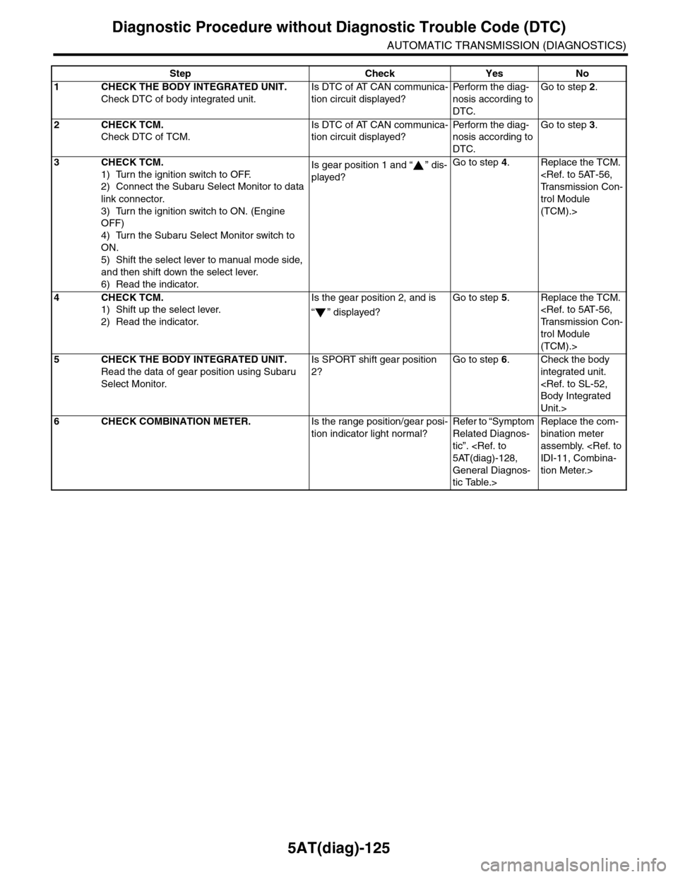
5AT(diag)-125
Diagnostic Procedure without Diagnostic Trouble Code (DTC)
AUTOMATIC TRANSMISSION (DIAGNOSTICS)
Step Check Yes No
1CHECK THE BODY INTEGRATED UNIT.
Check DTC of body integrated unit.
Is DTC of AT CAN communica-
tion circuit displayed?
Pe r for m t h e d ia g -
nosis according to
DTC.
Go to step 2.
2CHECK TCM.
Check DTC of TCM.
Is DTC of AT CAN communica-
tion circuit displayed?
Pe r for m t h e d ia g -
nosis according to
DTC.
Go to step 3.
3CHECK TCM.
1) Turn the ignition switch to OFF.
2) Connect the Subaru Select Monitor to data
link connector.
3) Turn the ignition switch to ON. (Engine
OFF)
4) Turn the Subaru Select Monitor switch to
ON.
5) Shift the select lever to manual mode side,
and then shift down the select lever.
6) Read the indicator.
Is gear position 1 and “ ” dis-
played?
Go to step 4.Replace the TCM.
trol Module
(TCM).>
4CHECK TCM.
1) Shift up the select lever.
2) Read the indicator.
Is the gear position 2, and is
“” displayed?
Go to step 5.Replace the TCM.
trol Module
(TCM).>
5CHECK THE BODY INTEGRATED UNIT.
Read the data of gear position using Subaru
Select Monitor.
Is SPORT shift gear position
2?
Go to step 6.Check the body
integrated unit.
Unit.>
6CHECK COMBINATION METER.Is the range position/gear posi-
tion indicator light normal?
Refer to “Symptom
Related Diagnos-
tic”.
General Diagnos-
tic Table.>
Replace the com-
bination meter
assembly.
tion Meter.>
Page 2244 of 2453
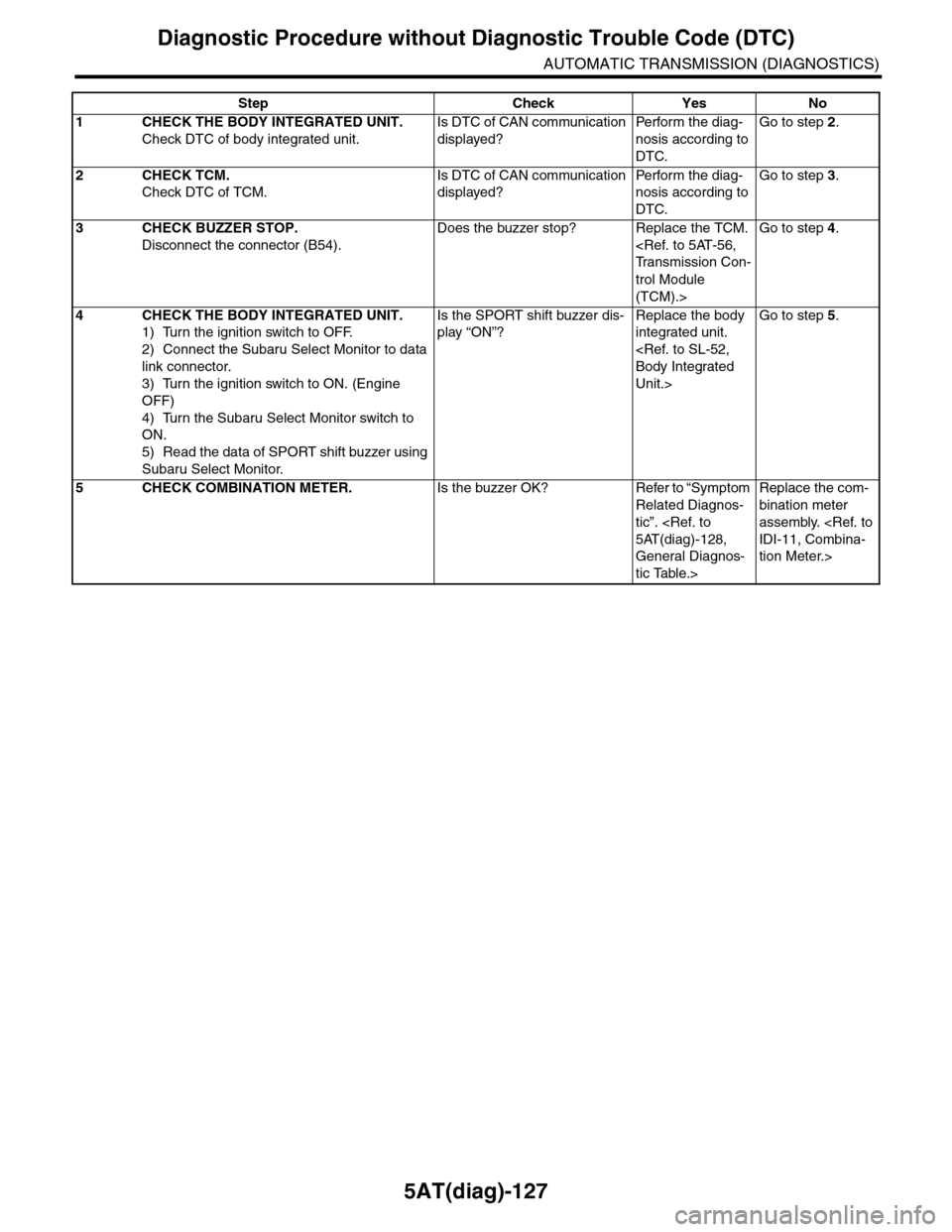
5AT(diag)-127
Diagnostic Procedure without Diagnostic Trouble Code (DTC)
AUTOMATIC TRANSMISSION (DIAGNOSTICS)
Step Check Yes No
1CHECK THE BODY INTEGRATED UNIT.
Check DTC of body integrated unit.
Is DTC of CAN communication
displayed?
Pe r for m t h e d ia g -
nosis according to
DTC.
Go to step 2.
2CHECK TCM.
Check DTC of TCM.
Is DTC of CAN communication
displayed?
Pe r for m t h e d ia g -
nosis according to
DTC.
Go to step 3.
3CHECK BUZZER STOP.
Disconnect the connector (B54).
Does the buzzer stop? Replace the TCM.
trol Module
(TCM).>
Go to step 4.
4CHECK THE BODY INTEGRATED UNIT.
1) Turn the ignition switch to OFF.
2) Connect the Subaru Select Monitor to data
link connector.
3) Turn the ignition switch to ON. (Engine
OFF)
4) Turn the Subaru Select Monitor switch to
ON.
5) Read the data of SPORT shift buzzer using
Subaru Select Monitor.
Is the SPORT shift buzzer dis-
play “ON”?
Replace the body
integrated unit.
Unit.>
Go to step 5.
5CHECK COMBINATION METER.Is the buzzer OK? Refer to “Symptom
Related Diagnos-
tic”.
General Diagnos-
tic Table.>
Replace the com-
bination meter
assembly.
tion Meter.>
Page 2265 of 2453
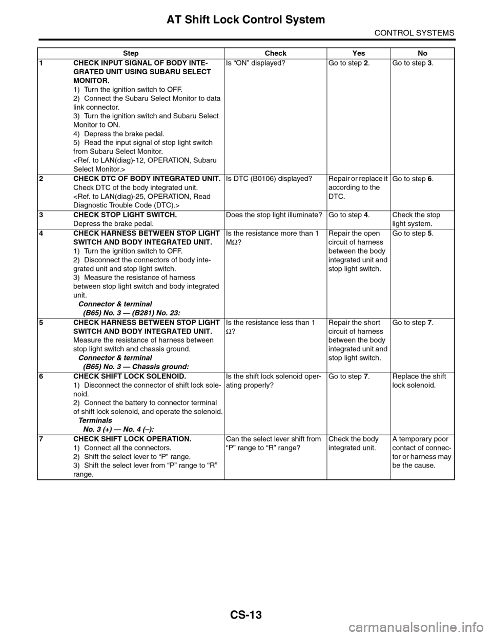
CS-13
AT Shift Lock Control System
CONTROL SYSTEMS
Step Check Yes No
1CHECK INPUT SIGNAL OF BODY INTE-
GRATED UNIT USING SUBARU SELECT
MONITOR.
1) Turn the ignition switch to OFF.
2) Connect the Subaru Select Monitor to data
link connector.
3) Turn the ignition switch and Subaru Select
Monitor to ON.
4) Depress the brake pedal.
5) Read the input signal of stop light switch
from Subaru Select Monitor.
Is “ON” displayed? Go to step 2.Go to step 3.
2CHECK DTC OF BODY INTEGRATED UNIT.
Check DTC of the body integrated unit.
Is DTC (B0106) displayed? Repair or replace it
according to the
DTC.
Go to step 6.
3CHECK STOP LIGHT SWITCH.
Depress the brake pedal.
Does the stop light illuminate? Go to step 4.Check the stop
light system.
4CHECK HARNESS BETWEEN STOP LIGHT
SWITCH AND BODY INTEGRATED UNIT.
1) Turn the ignition switch to OFF.
2) Disconnect the connectors of body inte-
grated unit and stop light switch.
3) Measure the resistance of harness
between stop light switch and body integrated
unit.
Connector & terminal
(B65) No. 3 — (B281) No. 23:
Is the resistance more than 1
MΩ?
Repair the open
circuit of harness
between the body
integrated unit and
stop light switch.
Go to step 5.
5CHECK HARNESS BETWEEN STOP LIGHT
SWITCH AND BODY INTEGRATED UNIT.
Measure the resistance of harness between
stop light switch and chassis ground.
Connector & terminal
(B65) No. 3 — Chassis ground:
Is the resistance less than 1
Ω?
Repair the short
circuit of harness
between the body
integrated unit and
stop light switch.
Go to step 7.
6CHECK SHIFT LOCK SOLENOID.
1) Disconnect the connector of shift lock sole-
noid.
2) Connect the battery to connector terminal
of shift lock solenoid, and operate the solenoid.
Te r m i n a l s
No. 3 (+) — No. 4 (–):
Is the shift lock solenoid oper-
ating properly?
Go to step 7.Replace the shift
lock solenoid.
7CHECK SHIFT LOCK OPERATION.
1) Connect all the connectors.
2) Shift the select lever to “P” range.
3) Shift the select lever from “P” range to “R”
range.
Can the select lever shift from
“P” range to “R” range?
Check the body
integrated unit.
A temporary poor
contact of connec-
tor or harness may
be the cause.
Page 2267 of 2453
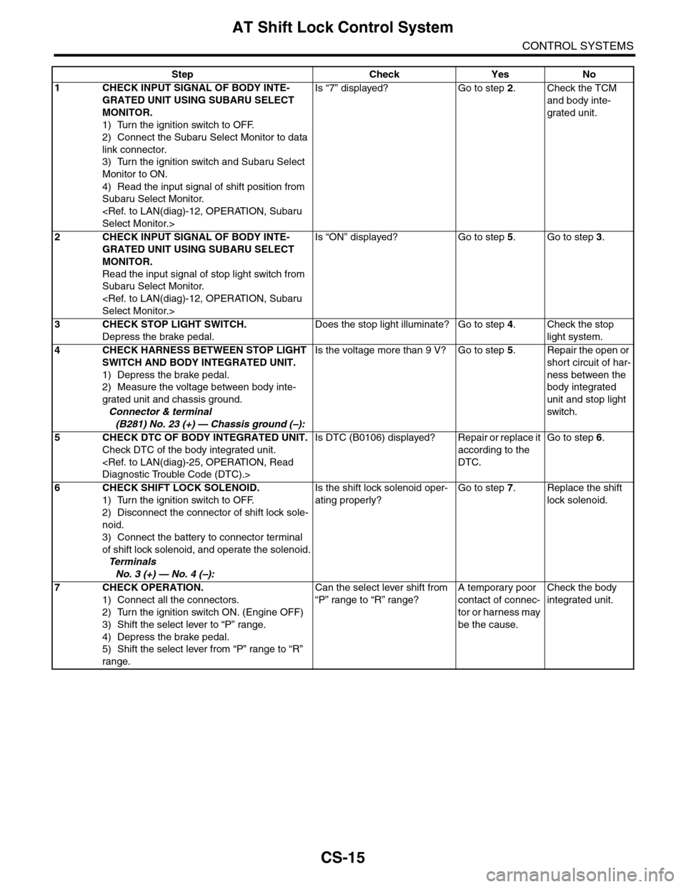
CS-15
AT Shift Lock Control System
CONTROL SYSTEMS
Step Check Yes No
1CHECK INPUT SIGNAL OF BODY INTE-
GRATED UNIT USING SUBARU SELECT
MONITOR.
1) Turn the ignition switch to OFF.
2) Connect the Subaru Select Monitor to data
link connector.
3) Turn the ignition switch and Subaru Select
Monitor to ON.
4) Read the input signal of shift position from
Subaru Select Monitor.
Is “7” displayed? Go to step 2.Check the TCM
and body inte-
grated unit.
2CHECK INPUT SIGNAL OF BODY INTE-
GRATED UNIT USING SUBARU SELECT
MONITOR.
Read the input signal of stop light switch from
Subaru Select Monitor.
Is “ON” displayed? Go to step 5.Go to step 3.
3CHECK STOP LIGHT SWITCH.
Depress the brake pedal.
Does the stop light illuminate? Go to step 4.Check the stop
light system.
4CHECK HARNESS BETWEEN STOP LIGHT
SWITCH AND BODY INTEGRATED UNIT.
1) Depress the brake pedal.
2) Measure the voltage between body inte-
grated unit and chassis ground.
Connector & terminal
(B281) No. 23 (+) — Chassis ground (–):
Is the voltage more than 9 V? Go to step 5.Repair the open or
short circuit of har-
ness between the
body integrated
unit and stop light
switch.
5CHECK DTC OF BODY INTEGRATED UNIT.
Check DTC of the body integrated unit.
Is DTC (B0106) displayed? Repair or replace it
according to the
DTC.
Go to step 6.
6CHECK SHIFT LOCK SOLENOID.
1) Turn the ignition switch to OFF.
2) Disconnect the connector of shift lock sole-
noid.
3) Connect the battery to connector terminal
of shift lock solenoid, and operate the solenoid.
Te r m i n a l s
No. 3 (+) — No. 4 (–):
Is the shift lock solenoid oper-
ating properly?
Go to step 7.Replace the shift
lock solenoid.
7CHECK OPERATION.
1) Connect all the connectors.
2) Turn the ignition switch ON. (Engine OFF)
3) Shift the select lever to “P” range.
4) Depress the brake pedal.
5) Shift the select lever from “P” range to “R”
range.
Can the select lever shift from
“P” range to “R” range?
A temporary poor
contact of connec-
tor or harness may
be the cause.
Check the body
integrated unit.