fuse diagram SUBARU TRIBECA 2009 1.G Service Owner's Manual
[x] Cancel search | Manufacturer: SUBARU, Model Year: 2009, Model line: TRIBECA, Model: SUBARU TRIBECA 2009 1.GPages: 2453, PDF Size: 46.32 MB
Page 688 of 2453
SR-4
Sunroof Control System
SUNROOF/T-TOP/CONVERTIBLE TOP (SUNROOF)
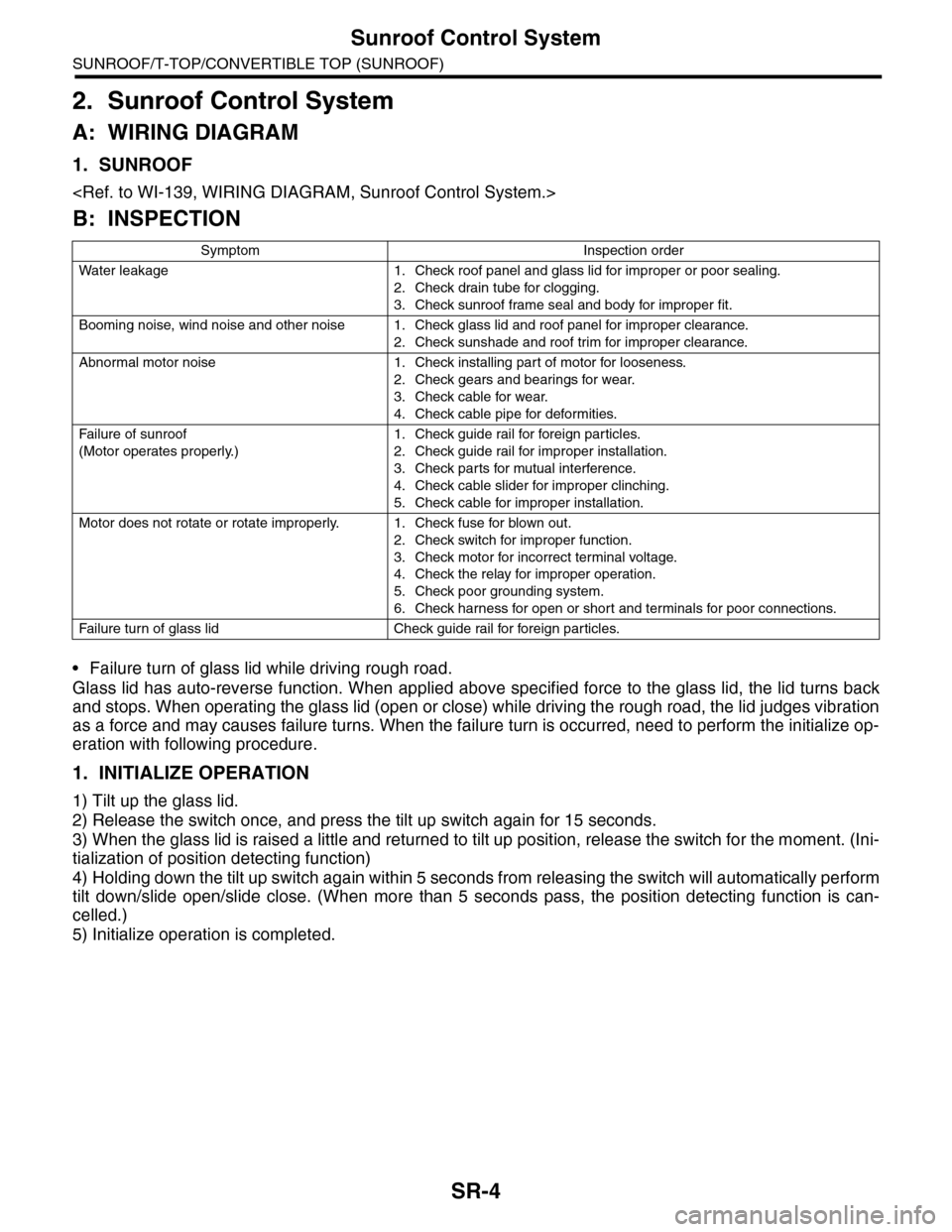
2. Sunroof Control System
A: WIRING DIAGRAM
1. SUNROOF
B: INSPECTION
•Failure turn of glass lid while driving rough road.
Glass lid has auto-reverse function. When applied above specified force to the glass lid, the lid turns back
and stops. When operating the glass lid (open or close) while driving the rough road, the lid judges vibration
as a force and may causes failure turns. When the failure turn is occurred, need to perform the initialize op-
eration with following procedure.
1. INITIALIZE OPERATION
1) Tilt up the glass lid.
2) Release the switch once, and press the tilt up switch again for 15 seconds.
3) When the glass lid is raised a little and returned to tilt up position, release the switch for the moment. (Ini-
tialization of position detecting function)
4) Holding down the tilt up switch again within 5 seconds from releasing the switch will automatically perform
tilt down/slide open/slide close. (When more than 5 seconds pass, the position detecting function is can-
celled.)
5) Initialize operation is completed.
Symptom Inspection order
Wa t er l e ak ag e 1 . Che ck r o o f p a ne l a n d g la ss li d fo r i mp r o pe r or p oo r se al i ng .
2. Check drain tube for clogging.
3. Check sunroof frame seal and body for improper fit.
Booming noise, wind noise and other noise 1. Check glass lid and roof panel for improper clearance.
2. Check sunshade and roof trim for improper clearance.
Abnormal motor noise 1. Check installing part of motor for looseness.
2. Check gears and bearings for wear.
3. Check cable for wear.
4. Check cable pipe for deformities.
Fai l ur e of su n r oo f
(Motor operates properly.)
1. Check guide rail for foreign particles.
2. Check guide rail for improper installation.
3. Check parts for mutual interference.
4. Check cable slider for improper clinching.
5. Check cable for improper installation.
Motor does not rotate or rotate improperly. 1. Check fuse for blown out.
2. Check switch for improper function.
3. Check motor for incorrect terminal voltage.
4. Check the relay for improper operation.
5. Check poor grounding system.
6. Check harness for open or short and terminals for poor connections.
Fai l ur e tu r n o f gl a ss l i d Ch e ck gu i de ra il fo r fo r e ig n p a r ti cl e s.
Page 700 of 2453
WW-5
Wiper and Washer System
WIPER AND WASHER SYSTEMS
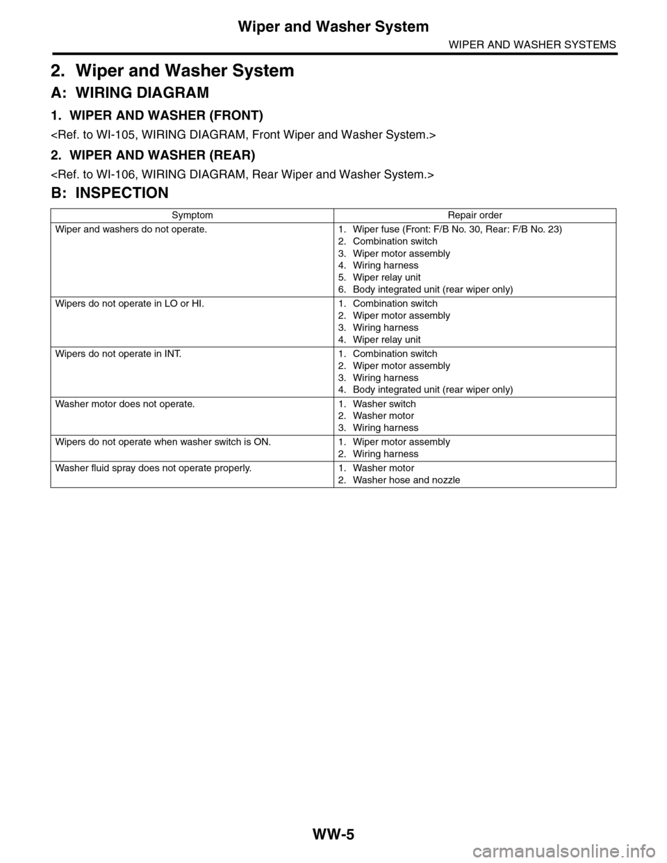
2. Wiper and Washer System
A: WIRING DIAGRAM
1. WIPER AND WASHER (FRONT)
2. WIPER AND WASHER (REAR)
B: INSPECTION
Symptom Repair order
Wiper and washers do not operate. 1. Wiper fuse (Front: F/B No. 30, Rear : F/B No. 23)
2. Combination switch
3. Wiper motor assembly
4. Wiring harness
5. Wiper relay unit
6. Body integrated unit (rear wiper only)
Wipers do not operate in LO or HI. 1. Combination switch
2. Wiper motor assembly
3. Wiring harness
4. Wiper relay unit
Wipers do not operate in INT. 1. Combination switch
2. Wiper motor assembly
3. Wiring harness
4. Body integrated unit (rear wiper only)
Wa sh e r mo to r do e s n ot o pe ra t e. 1 . Wa sh e r swit c h
2. Washer motor
3. Wiring harness
Wipers do not operate when washer switch is ON. 1. Wiper motor assembly
2. Wiring harness
Wa sh e r fl u id sp ray do e s n ot op e ra te pr o p er l y. 1 . Wa sh e r m ot o r
2. Washer hose and nozzle
Page 964 of 2453
TPM(diag)-14
Subaru Select Monitor
TIRE PRESSURE MONITORING SYSTEM (DIAGNOSTICS)
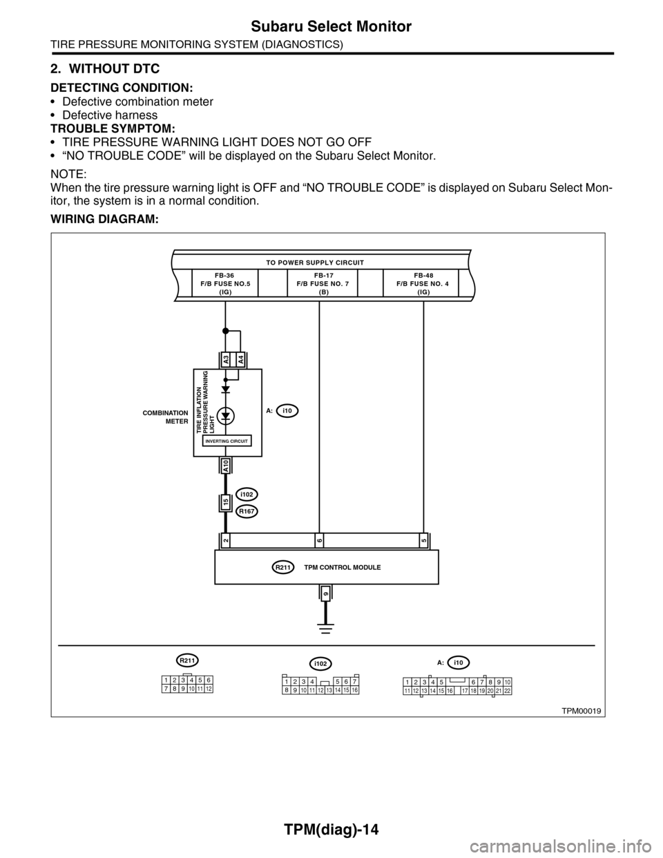
2. WITHOUT DTC
DETECTING CONDITION:
•Defective combination meter
•Defective harness
TROUBLE SYMPTOM:
•TIRE PRESSURE WARNING LIGHT DOES NOT GO OFF
•“NO TROUBLE CODE” will be displayed on the Subaru Select Monitor.
NOTE:
When the tire pressure warning light is OFF and “NO TROUBLE CODE” is displayed on Subaru Select Mon-
itor, the system is in a normal condition.
WIRING DIAGRAM:
TPM00019
TO POWER SUPPLY CIRCUIT
FB-36 F/B FUSE NO.5(IG)
26
COMBINATIONMETERA:i10
A3
A10
TIRE INFLATION PRESSURE WARNINGLIGHT
FB-17F/B FUSE NO. 7 (B)
i102
R167
R211
FB-48F/B FUSE NO. 4 (IG)
A4
INVERTING CIRCUIT
15
5
9
TPM CONTROL MODULE
i102
1238910411 12 1314 15 16567
A:i10
12345 678910111219 20 2113 14 15 161718 22
R211
123456789101112
Page 970 of 2453
TPM(diag)-20
Tire Pressure Warning Light/Trouble Indicator Light Illumination Pattern (DTC)
TIRE PRESSURE MONITORING SYSTEM (DIAGNOSTICS)
1) When the tire pressure warning light does not illuminate in accordance with this illumination pattern, there
must be an electrical malfunction.
2) When tire pressure warning light does not go off, check the tire pressure monitoring control module/warn-
ing light circuit and the combination meter circuit.
(DTC).>
NOTE:
If the problem is fixed while driving at approximately 40 km/h (25 MPH) after the tire pressure warning light
blinks/lights, the warning light goes out and the tire pressure monitor system operates normally. (If there is
a decrease in tire pressure, or malfunction of the system, the past malfunctions are displayed.)
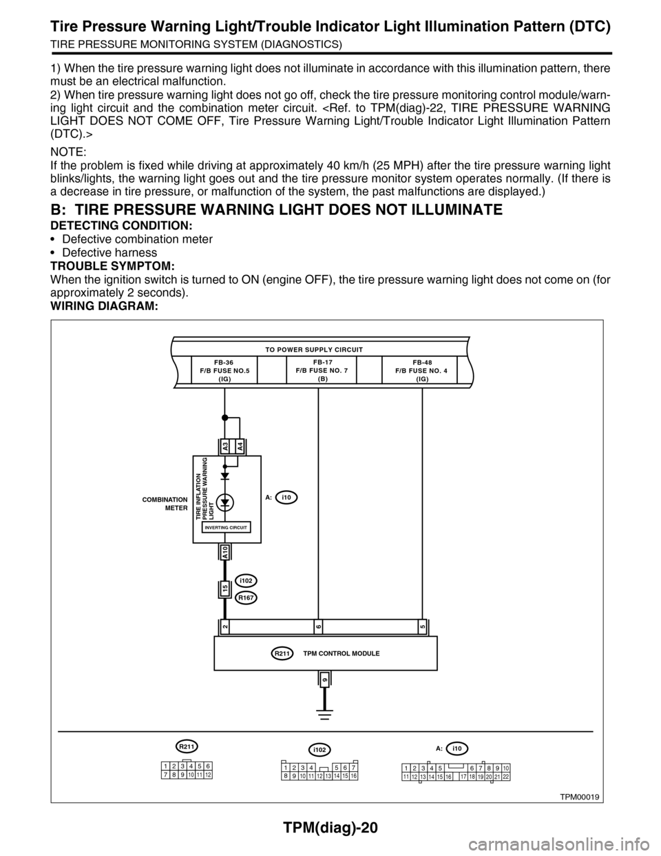
B: TIRE PRESSURE WARNING LIGHT DOES NOT ILLUMINATE
DETECTING CONDITION:
•Defective combination meter
•Defective harness
TROUBLE SYMPTOM:
When the ignition switch is turned to ON (engine OFF), the tire pressure warning light does not come on (for
approximately 2 seconds).
WIRING DIAGRAM:
TPM00019
TO POWER SUPPLY CIRCUIT
FB-36 F/B FUSE NO.5(IG)
26
COMBINATIONMETERA:i10
A3
A10
TIRE INFLATION PRESSURE WARNINGLIGHT
FB-17F/B FUSE NO. 7 (B)
i102
R167
R211
FB-48F/B FUSE NO. 4 (IG)
A4
INVERTING CIRCUIT
15
5
9
TPM CONTROL MODULE
i102
1238910411 12 1314 15 16567
A:i10
12345 678910111219 20 2113 14 15 161718 22
R211
123456789101112
Page 972 of 2453
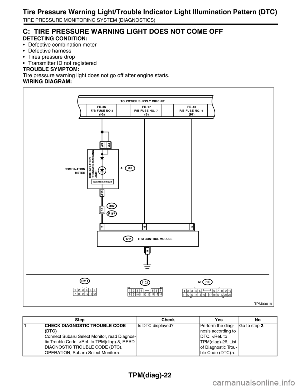
TPM(diag)-22
Tire Pressure Warning Light/Trouble Indicator Light Illumination Pattern (DTC)
TIRE PRESSURE MONITORING SYSTEM (DIAGNOSTICS)
C: TIRE PRESSURE WARNING LIGHT DOES NOT COME OFF
DETECTING CONDITION:
•Defective combination meter
•Defective harness
•Tires pressure drop
•Transmitter ID not registered
TROUBLE SYMPTOM:
Tire pressure warning light does not go off after engine starts.
WIRING DIAGRAM:
TPM00019
TO POWER SUPPLY CIRCUIT
FB-36 F/B FUSE NO.5(IG)
26
COMBINATIONMETERA:i10
A3
A10
TIRE INFLATION PRESSURE WARNINGLIGHT
FB-17F/B FUSE NO. 7 (B)
i102
R167
R211
FB-48F/B FUSE NO. 4 (IG)
A4
INVERTING CIRCUIT
15
5
9
TPM CONTROL MODULE
i102
1238910411 12 1314 15 16567
A:i10
12345 678910111219 20 2113 14 15 161718 22
R211
123456789101112
Step Check Yes No
1CHECK DIAGNOSTIC TROUBLE CODE
(DTC)
Connect Subaru Select Monitor, read Diagnos-
tic Trouble Code.
OPERATION, Subaru Select Monitor.>
Is DTC displayed? Perform the diag-
nosis according to
DTC.
of Diagnostic Trou-
ble Code (DTC).>
Go to step 2.
Page 974 of 2453
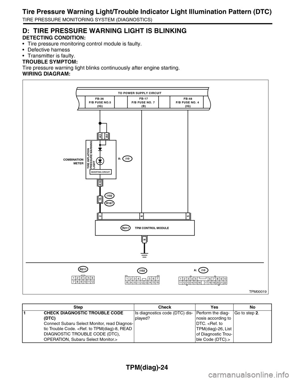
TPM(diag)-24
Tire Pressure Warning Light/Trouble Indicator Light Illumination Pattern (DTC)
TIRE PRESSURE MONITORING SYSTEM (DIAGNOSTICS)
D: TIRE PRESSURE WARNING LIGHT IS BLINKING
DETECTING CONDITION:
•Tire pressure monitoring control module is faulty.
•Defective harness
•Transmitter is faulty.
TROUBLE SYMPTOM:
Tire pressure warning light blinks continuously after engine starting.
WIRING DIAGRAM:
TPM00019
TO POWER SUPPLY CIRCUIT
FB-36 F/B FUSE NO.5(IG)
26
COMBINATIONMETERA:i10
A3
A10
TIRE INFLATION PRESSURE WARNINGLIGHT
FB-17F/B FUSE NO. 7 (B)
i102
R167
R211
FB-48F/B FUSE NO. 4 (IG)
A4
INVERTING CIRCUIT
15
5
9
TPM CONTROL MODULE
i102
1238910411 12 1314 15 16567
A:i10
12345 678910111219 20 2113 14 15 161718 22
R211
123456789101112
Step Check Yes No
1CHECK DIAGNOSTIC TROUBLE CODE
(DTC)
Connect Subaru Select Monitor, read Diagnos-
tic Trouble Code.
OPERATION, Subaru Select Monitor.>
Is diagnostics code (DTC) dis-
played?
Pe r for m t h e d ia g -
nosis according to
DTC.
of Diagnostic Trou-
ble Code (DTC).>
Go to step 2.
Page 984 of 2453
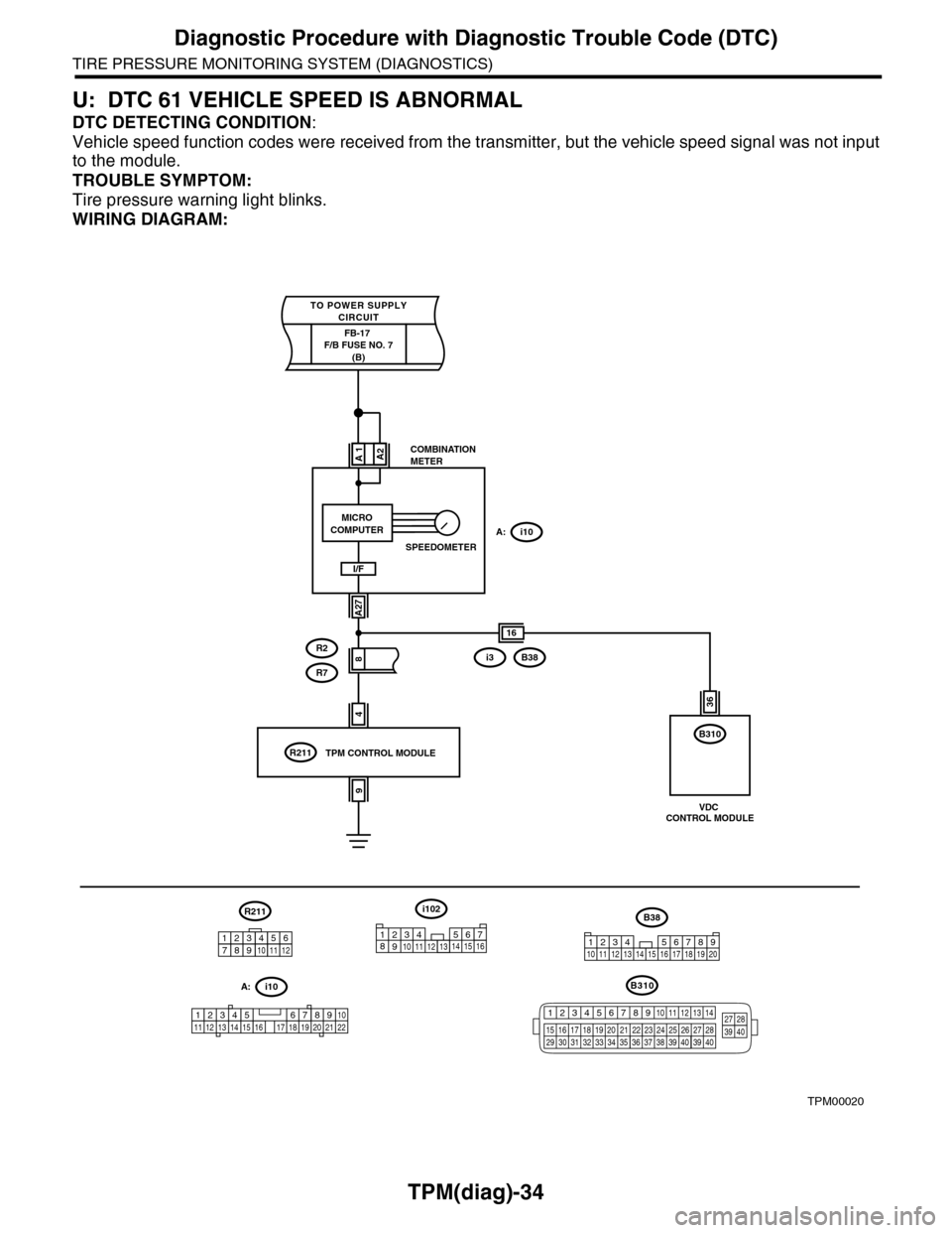
TPM(diag)-34
Diagnostic Procedure with Diagnostic Trouble Code (DTC)
TIRE PRESSURE MONITORING SYSTEM (DIAGNOSTICS)
U: DTC 61 VEHICLE SPEED IS ABNORMAL
DTC DETECTING CONDITION:
Vehicle speed function codes were received from the transmitter, but the vehicle speed signal was not input
to the module.
TROUBLE SYMPTOM:
Tire pressure warning light blinks.
WIRING DIAGRAM:
TPM00020
4
COMBINATIONMETER
A:i10
A1
A27
R2
R7
R211
A2
I/F
8
9
TPM CONTROL MODULE
i102
1238910411 12 1314 15 16567
A:i10
12345 678910111219 20 2113 14 15 161718 22
R211
16
B310
MICROCOMPUTER
SPEEDOMETER
FB-17 F/B FUSE NO. 7(B)
TO POWER SUPPLYCIRCUIT
i3B38
B38
1234 5678910 11 12 13 14 15 16 17 18 19 20
36
VDC CONTROL MODULE
123456789101112
B310
12345678910 11 12 13 14
15 16 17 18 19 2021 22 23 24 25 26 27 2829 30 31 32 33 3435 36 37 38 39403940
27 283940
Page 1126 of 2453
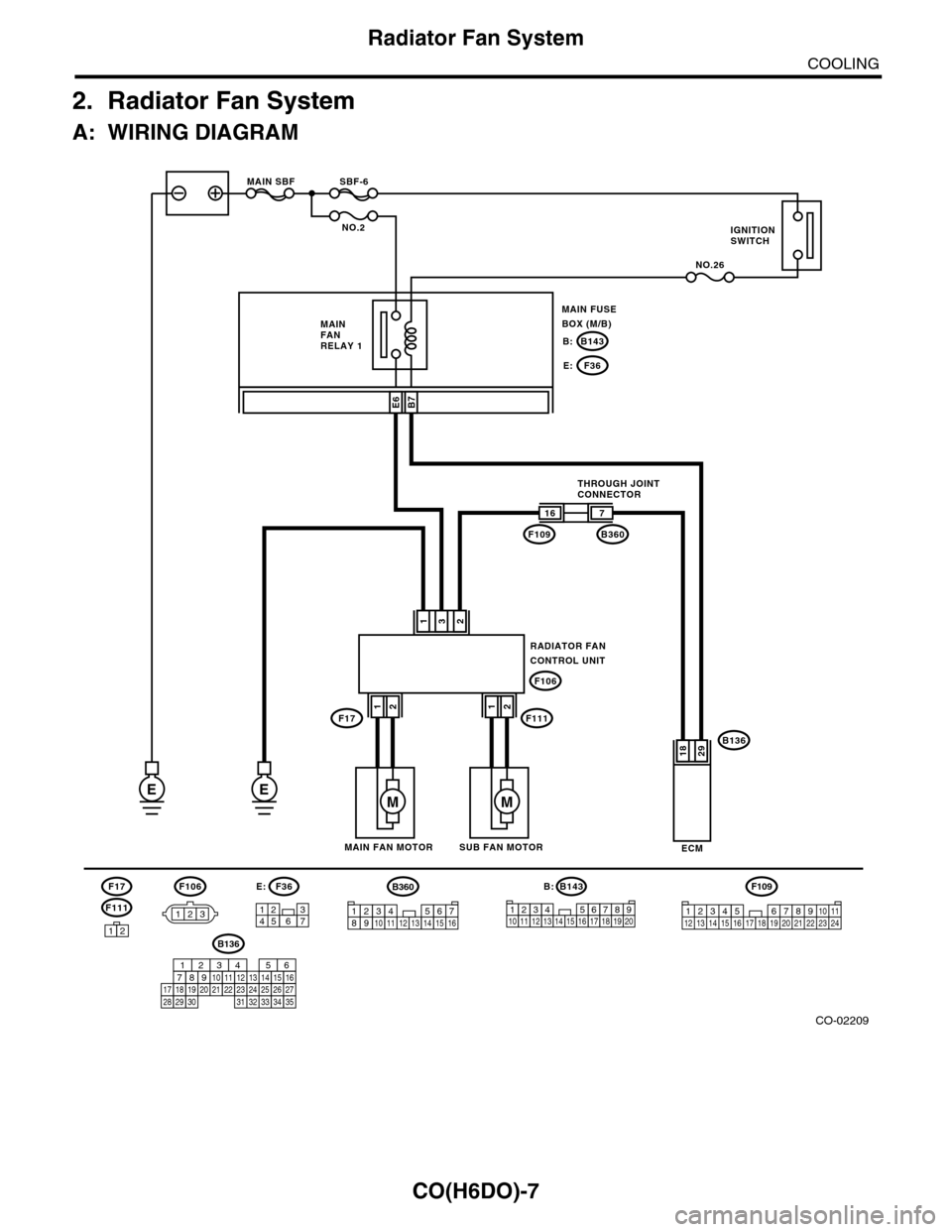
CO(H6DO)-7
Radiator Fan System
COOLING
2. Radiator Fan System
A: WIRING DIAGRAM
CO-02209
RADIATOR FANCONTROL UNIT
132
B136
ECM
16
F109
F106
7
B360
2918
F106
123
B7
E
SBF-6MAIN SBF
NO.2
NO.26
B143B:
F36E:
E6
3127456
F36E:B143
123456712131415161718
B:
8191192010
EM
SUB FAN MOTORMAIN FAN MOTOR
THROUGH JOINTCONNECTOR
MAIN FANRELAY 1
MAIN FUSEBOX (M/B)
IGNITIONSWITCH
F17F11112
M
12
F111
F17
12
F109
3412 8910 1112 13 14 15 16 17 18 19 20 21 22 23 24567
B136
16101112131415252430
9871718192028212223293231
123456
2726333435
B360
12345678910111213141516
Page 2210 of 2453
5AT(diag)-93
Diagnostic Procedure with Diagnostic Trouble Code (DTC)
AUTOMATIC TRANSMISSION (DIAGNOSTICS)
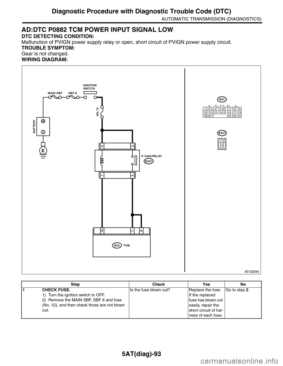
AD:DTC P0882 TCM POWER INPUT SIGNAL LOW
DTC DETECTING CONDITION:
Malfunction of PVIGN power supply relay or open, short circuit of PVIGN power supply circuit.
TROUBLE SYMPTOM:
Gear is not changed.
WIRING DIAGRAM:
AT-03294
8710
B54
B357
TCM
B54
B357
12789563410 11 1219 20 2113 14 15 16 17 18222324
MAIN SBF SBF-8
NO.12
E
32
41
1234
BATTERY
IGNITIONSWITCH
1234
1234
RELAYP-VING
Step Check Yes No
1CHECK FUSE.
1) Turn the ignition switch to OFF.
2) Remove the MAIN SBF, SBF 8 and fuse
(No. 12), and then check those are not blown
out.
Is the fuse blown out? Replace the fuse.
If the replaced
fuse has blown out
easily, repair the
short circuit of har-
ness of each fuse.
Go to step 2.
Page 2287 of 2453
WI-3
Basic Diagnostic Procedure
WIRING SYSTEM
1. Basic Diagnostic Procedure
A: BASIC PROCEDURES
1. GENERAL DESCRIPTION
The most important purpose of diagnostics is to
quickly determine which part is malfunctioning, to
save time and labor.
2. IDENTIFICATION OF TROUBLE SYMP-
TOM
Determine what the problem is based on the symp-
tom.
3. PROBABLE CAUSE OF TROUBLE
Look at the wiring diagram and check the system’s
circuit. Then check the switch, relay, fuse, ground,
etc.
4. LOCATION AND REPAIR OF TROUBLE
1) Using the diagnostics, narrow down the causes.
2) If necessary, use a voltmeter, ohmmeter, etc.
3) Before replacing certain component parts
(switch, relay, etc.), check the power supply,
ground, for open wiring harness, poor connectors,
etc. If no problem is encountered, check the com-
ponent parts.
5. SYSTEM OPERATION CHECK
After repairing, ensure that the system operates
properly.
B: BASIC INSPECTION
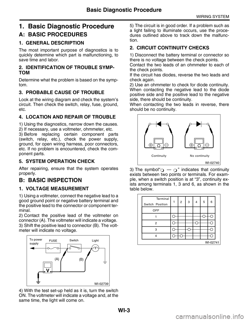
1. VOLTAGE MEASUREMENT
1) Using a voltmeter, connect the negative lead to a
good ground point or negative battery terminal and
the positive lead to the connector or component ter-
minal.
2) Contact the positive lead of the voltmeter on
connector (A). The voltmeter will indicate a voltage.
3) Shift the positive lead to connector (B). The volt-
meter will indicate no voltage.
4) With the test set-up held as it is, turn the switch
ON. The voltmeter will indicate a voltage and, at the
same time, the light will come on.
5) The circuit is in good order. If a problem such as
a light failing to illuminate occurs, use the proce-
dures outlined above to track down the malfunc-
tion.
2. CIRCUIT CONTINUITY CHECKS
1) Disconnect the battery terminal or connector so
there is no voltage between the check points.
Contact the two leads of an ohmmeter to each of
the check points.
If the circuit has diodes, reverse the two leads and
check again.
2) Use an ohmmeter to check for diode continuity.
When contacting the negative lead to the diode
positive side and the positive lead to the negative
side, there should be continuity.
When contacting the two leads in reverse, there
should be no continuity.
3) The symbol“ — ” indicates that continuity
exists between two points or terminals. For exam-
ple, when a switch position is at “3”, continuity ex-
ists among terminals 1, 3 and 6, as shown in the
table below.
WI-02739
To powerFUSEsupplySwitchLight
V
(A)(B)
WI-02740
Continuity No continuity
�