catalytic converter SUBARU TRIBECA 2009 1.G Service Workshop Manual
[x] Cancel search | Manufacturer: SUBARU, Model Year: 2009, Model line: TRIBECA, Model: SUBARU TRIBECA 2009 1.GPages: 2453, PDF Size: 46.32 MB
Page 1151 of 2453
EC(H6DO)-3
Front Catalytic Converter
EMISSION CONTROL (AUX. EMISSION CONTROL DEVICES)
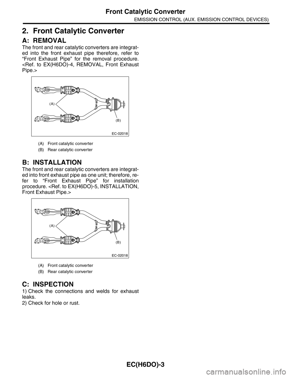
2. Front Catalytic Converter
A: REMOVAL
The front and rear catalytic converters are integrat-
ed into the front exhaust pipe therefore, refer to
“Front Exhaust Pipe” for the removal procedure.
B: INSTALLATION
The front and rear catalytic converters are integrat-
ed into front exhaust pipe as one unit; therefore, re-
fer to “Front Exhaust Pipe” for installation
procedure.
C: INSPECTION
1) Check the connections and welds for exhaust
leaks.
2) Check for hole or rust.
(A) Front catalytic converter
(B) Rear catalytic converter
(A) Front catalytic converter
(B) Rear catalytic converter
(A)
(B)
EC-02018
(A)
(B)
EC-02018
Page 1152 of 2453
EC(H6DO)-4
Rear Catalytic Converter
EMISSION CONTROL (AUX. EMISSION CONTROL DEVICES)
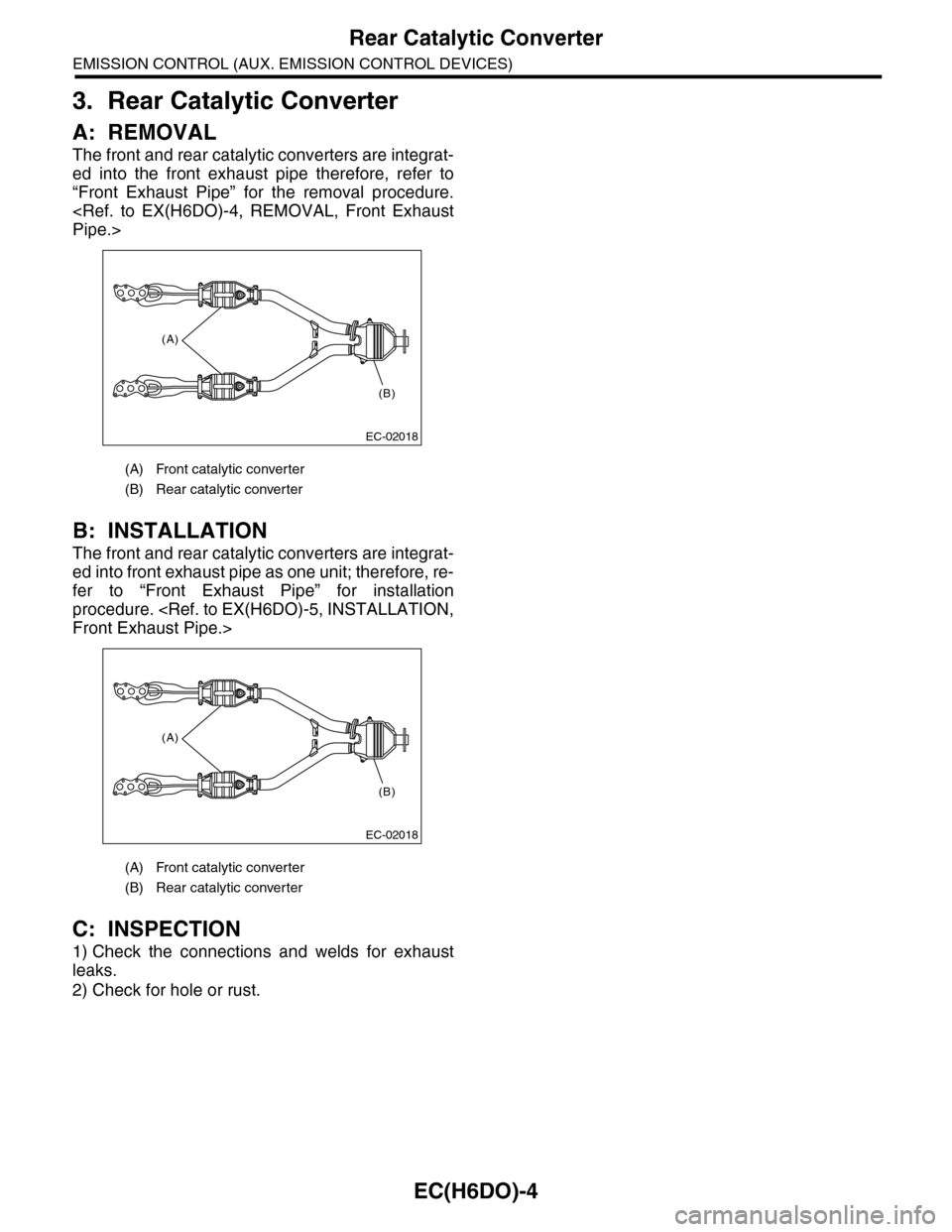
3. Rear Catalytic Converter
A: REMOVAL
The front and rear catalytic converters are integrat-
ed into the front exhaust pipe therefore, refer to
“Front Exhaust Pipe” for the removal procedure.
B: INSTALLATION
The front and rear catalytic converters are integrat-
ed into front exhaust pipe as one unit; therefore, re-
fer to “Front Exhaust Pipe” for installation
procedure.
C: INSPECTION
1) Check the connections and welds for exhaust
leaks.
2) Check for hole or rust.
(A) Front catalytic converter
(B) Rear catalytic converter
(A) Front catalytic converter
(B) Rear catalytic converter
(A)
(B)
EC-02018
(A)
(B)
EC-02018
Page 1172 of 2453
EN(H6DO)(diag)-11
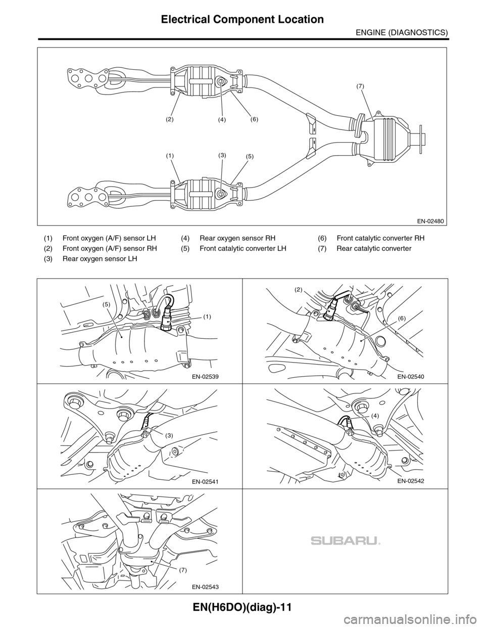
Electrical Component Location
ENGINE (DIAGNOSTICS)
(1) Front oxygen (A/F) sensor LH (4) Rear oxygen sensor RH (6) Front catalytic converter RH
(2) Front oxygen (A/F) sensor RH (5) Front catalytic converter LH (7) Rear catalytic converter
(3) Rear oxygen sensor LH
EN-02480
(2)
(1)(3)
(4)(6)
(7)
(5)
EN-02539
(5)
(1)
EN-02540
(2)
(6)
EN-02541
(3)
EN-02542
(4)
(7)
EN-02543
Page 1333 of 2453
EN(H6DO)(diag)-172
Diagnostic Procedure with Diagnostic Trouble Code (DTC)
ENGINE (DIAGNOSTICS)
Step Check Yes No
1CHECK ANY OTHER DTC ON DISPLAY.Is any other DTC displayed? Check DTC using
“List of Diagnostic
Tr o u b l e C o d e
(DTC)”.
69, List of Diag-
nostic Trouble
Code (DTC).>
NOTE:
In this case, it is
not necessary to
inspect DTC
P0133.
Go to step 2.
2 CHECK EXHAUST SYSTEM.
NOTE:Check the following item.
•Loose installation of front portion of exhaust
pipe onto cylinder heads
•Loose connection between front exhaust
pipe and front catalytic converter
•Damage of exhaust pipe resulting in a hole
Is there any fault in exhaust
system?
Repair the exhaust
system.
Replace the front
oxygen (A/F) sen-
sor.
Fr o nt Ox yg en ( A /
F) Sensor.>
Page 1360 of 2453
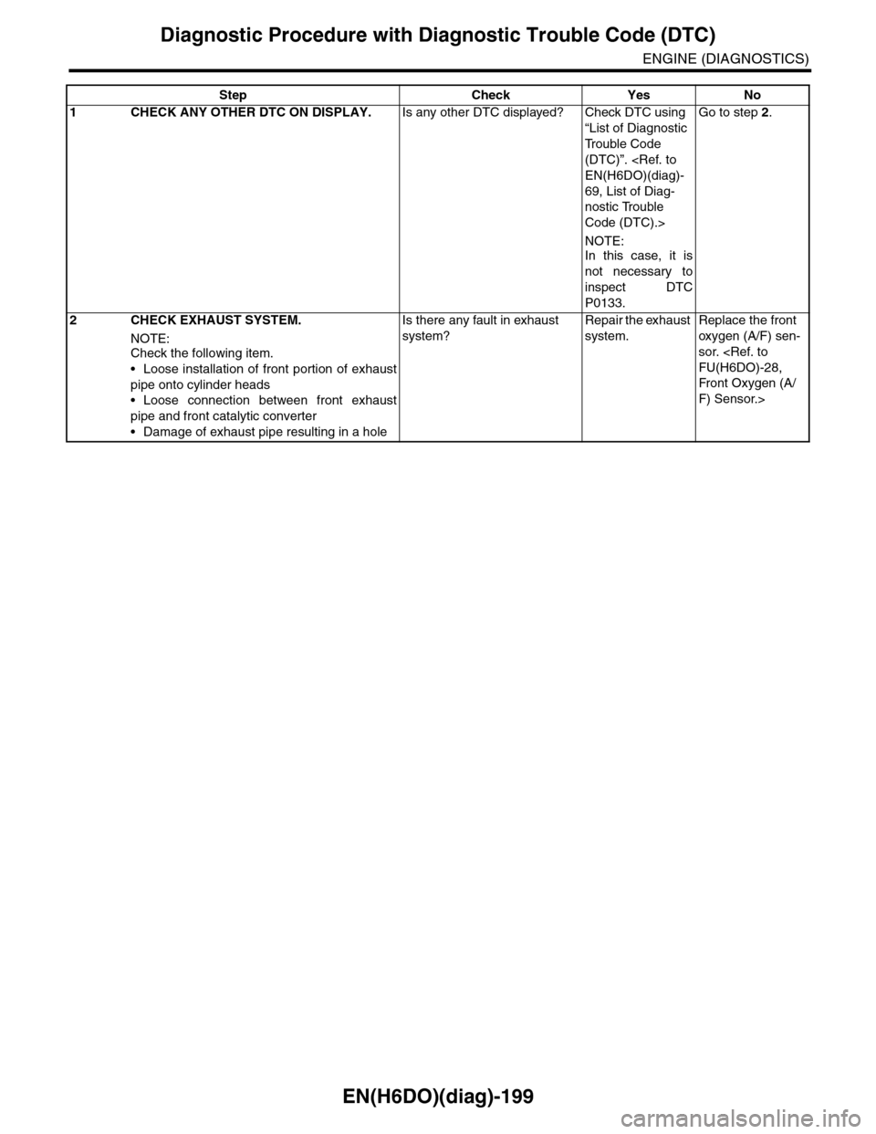
EN(H6DO)(diag)-199
Diagnostic Procedure with Diagnostic Trouble Code (DTC)
ENGINE (DIAGNOSTICS)
Step Check Yes No
1CHECK ANY OTHER DTC ON DISPLAY.Is any other DTC displayed? Check DTC using
“List of Diagnostic
Tr o u b l e C o d e
(DTC)”.
69, List of Diag-
nostic Trouble
Code (DTC).>
NOTE:
In this case, it is
not necessary to
inspect DTC
P0133.
Go to step 2.
2 CHECK EXHAUST SYSTEM.
NOTE:Check the following item.
•Loose installation of front portion of exhaust
pipe onto cylinder heads
•Loose connection between front exhaust
pipe and front catalytic converter
•Damage of exhaust pipe resulting in a hole
Is there any fault in exhaust
system?
Repair the exhaust
system.
Replace the front
oxygen (A/F) sen-
sor.
Fr o nt Ox yg en ( A /
F) Sensor.>
Page 1430 of 2453
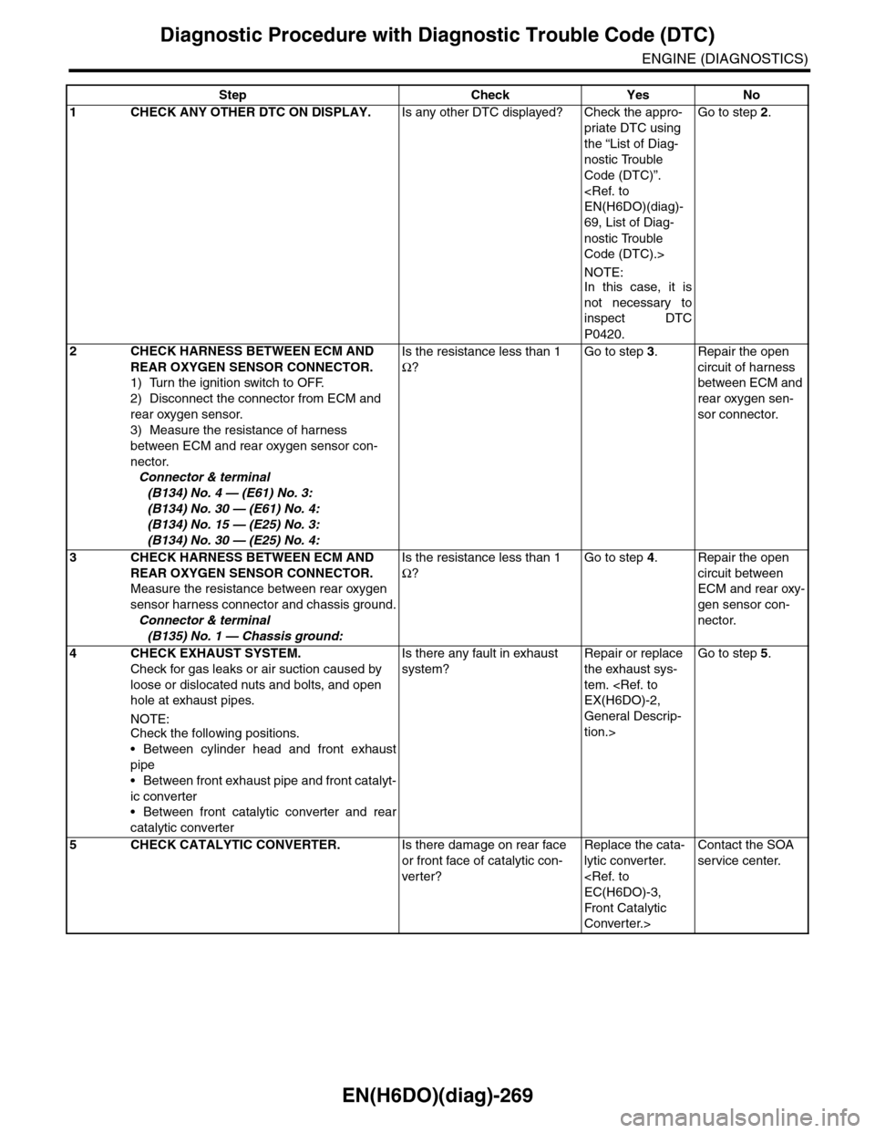
EN(H6DO)(diag)-269
Diagnostic Procedure with Diagnostic Trouble Code (DTC)
ENGINE (DIAGNOSTICS)
Step Check Yes No
1CHECK ANY OTHER DTC ON DISPLAY.Is any other DTC displayed? Check the appro-
priate DTC using
the “List of Diag-
nostic Trouble
Code (DTC)”.
69, List of Diag-
nostic Trouble
Code (DTC).>
NOTE:In this case, it is
not necessary to
inspect DTC
P0420.
Go to step 2.
2CHECK HARNESS BETWEEN ECM AND
REAR OXYGEN SENSOR CONNECTOR.
1) Turn the ignition switch to OFF.
2) Disconnect the connector from ECM and
rear oxygen sensor.
3) Measure the resistance of harness
between ECM and rear oxygen sensor con-
nector.
Connector & terminal
(B134) No. 4 — (E61) No. 3:
(B134) No. 30 — (E61) No. 4:
(B134) No. 15 — (E25) No. 3:
(B134) No. 30 — (E25) No. 4:
Is the resistance less than 1
Ω?
Go to step 3.Repair the open
circuit of harness
between ECM and
rear oxygen sen-
sor connector.
3CHECK HARNESS BETWEEN ECM AND
REAR OXYGEN SENSOR CONNECTOR.
Measure the resistance between rear oxygen
sensor harness connector and chassis ground.
Connector & terminal
(B135) No. 1 — Chassis ground:
Is the resistance less than 1
Ω?
Go to step 4.Repair the open
circuit between
ECM and rear oxy-
gen sensor con-
nector.
4 CHECK EXHAUST SYSTEM.
Check for gas leaks or air suction caused by
loose or dislocated nuts and bolts, and open
hole at exhaust pipes.
NOTE:Check the following positions.
•Between cylinder head and front exhaust
pipe
•Between front exhaust pipe and front catalyt-
ic converter
•Between front catalytic converter and rear
catalytic converter
Is there any fault in exhaust
system?
Repair or replace
the exhaust sys-
tem.
General Descrip-
tion.>
Go to step 5.
5CHECK CATALYTIC CONVERTER.Is there damage on rear face
or front face of catalytic con-
ver ter?
Replace the cata-
lytic converter.
Front Catalytic
Converter.>
Contact the SOA
service center.
Page 1557 of 2453
EX(H6DO)-3
General Description
EXHAUST
B: CAUTION
•Wear work clothing, including a cap, protective
goggles and protective shoes during operation.
•Remove contamination including dirt and corro-
sion before removal, installation or disassembly.
•Keep the disassembled parts in order and pro-
tect them from dust and dirt.
•Before removal, installation or disassembly, be
sure to clarify the failure. Avoid unnecessary re-
moval, installation, disassembly and replacement.
•Be careful not to burn yourself, because each
part on the vehicle is hot after running.
•Be sure to tighten fasteners including bolts and
nuts to the specified torque.
•Place shop jacks or rigid racks at the specified
points.
•Before disconnecting connectors of sensors or
units, be sure to disconnect the ground cable from
battery.
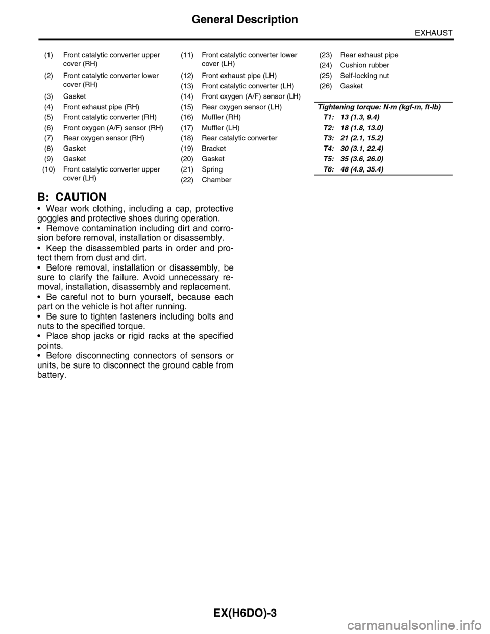
(1) Front catalytic converter upper
cover (RH)
(11) Front catalytic converter lower
cover (LH)
(23) Rear exhaust pipe
(24) Cushion rubber
(2) Front catalytic converter lower
cover (RH)
(12) Front exhaust pipe (LH) (25) Self-locking nut
(13) Front catalytic converter (LH) (26) Gasket
(3) Gasket (14) Front oxygen (A/F) sensor (LH)
(4) Front exhaust pipe (RH) (15) Rear oxygen sensor (LH)Tightening torque: N·m (kgf-m, ft-lb)
(5) Front catalytic converter (RH) (16) Muffler (RH)T1: 13 (1.3, 9.4)
(6) Front oxygen (A/F) sensor (RH) (17) Muffler (LH)T2: 18 (1.8, 13.0)
(7) Rear oxygen sensor (RH) (18) Rear catalytic converterT3: 21 (2.1, 15.2)
(8) Gasket (19) BracketT4: 30 (3.1, 22.4)
(9) Gasket (20) GasketT5: 35 (3.6, 26.0)
(10) Front catalytic converter upper
cover (LH)
(21) SpringT6: 48 (4.9, 35.4)
(22) Chamber
Page 1733 of 2453
GD(H6DO)-121
Diagnostic Trouble Code (DTC) Detecting Criteria
GENERAL DESCRIPTION
CB:DTC P0420 CATALYST SYSTEM EFFICIENCY BELOW THRESHOLD (BANK 1)
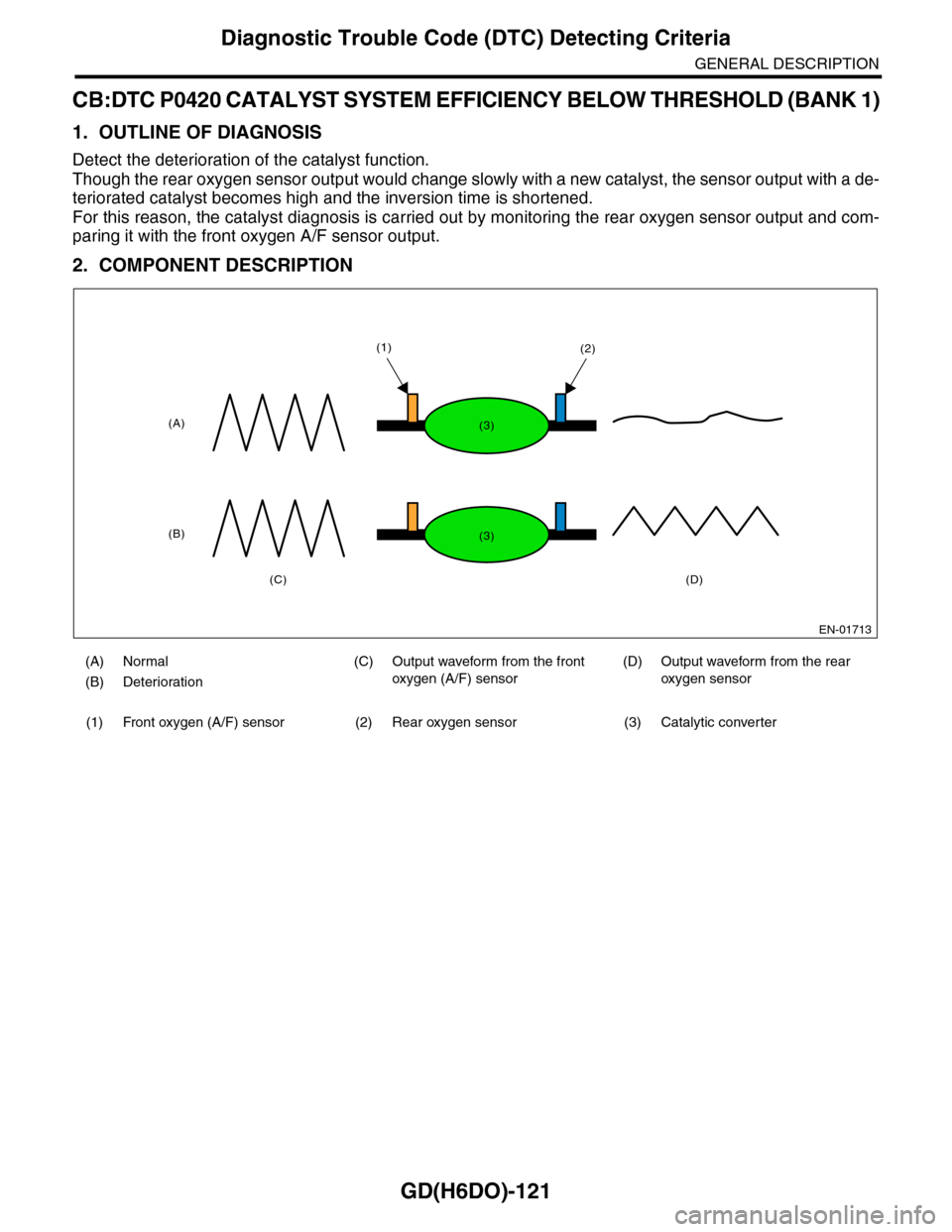
1. OUTLINE OF DIAGNOSIS
Detect the deterioration of the catalyst function.
Though the rear oxygen sensor output would change slowly with a new catalyst, the sensor output with a de-
teriorated catalyst becomes high and the inversion time is shortened.
For this reason, the catalyst diagnosis is carried out by monitoring the rear oxygen sensor output and com-
paring it with the front oxygen A/F sensor output.
2. COMPONENT DESCRIPTION
(A) Normal (C) Output waveform from the front
oxygen (A/F) sensor
(D) Output waveform from the rear
oxygen sensor(B) Deterioration
(1) Front oxygen (A/F) sensor (2) Rear oxygen sensor (3) Catalytic converter
EN-01713
(A)
(B)
(C)(D)
(1)(2)
(3)
(3)