security light SUBARU TRIBECA 2009 1.G Service Owner's Manual
[x] Cancel search | Manufacturer: SUBARU, Model Year: 2009, Model line: TRIBECA, Model: SUBARU TRIBECA 2009 1.GPages: 2453, PDF Size: 46.32 MB
Page 657 of 2453
SL-28
Security System
SECURITY AND LOCKS
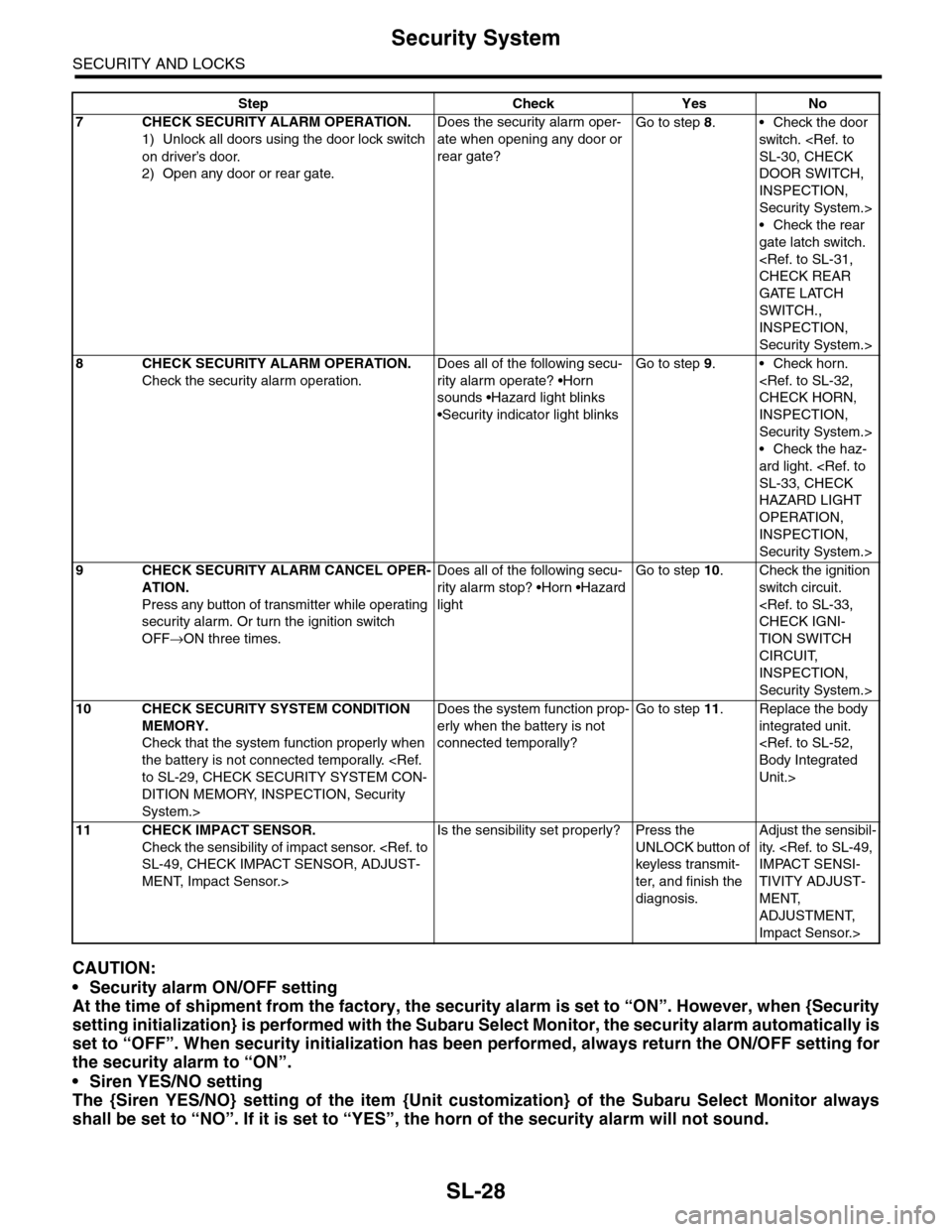
CAUTION:
•Security alarm ON/OFF setting
At the time of shipment from the factory, the security alarm is set to “ON”. However, when {Security
setting initialization} is performed with the Subaru Select Monitor, the security alarm automatically is
set to “OFF”. When security initialization has been performed, always return the ON/OFF setting for
the security alarm to “ON”.
•Siren YES/NO setting
The {Siren YES/NO} setting of the item {Unit customization} of the Subaru Select Monitor always
shall be set to “NO”. If it is set to “YES”, the horn of the security alarm will not sound.
7CHECK SECURITY ALARM OPERATION.
1) Unlock all doors using the door lock switch
on driver’s door.
2) Open any door or rear gate.
Does the security alarm oper-
ate when opening any door or
rear gate?
Go to step 8.•Check the door
switch.
DOOR SWITCH,
INSPECTION,
Security System.>
•Check the rear
gate latch switch.
GATE LATCH
SWITCH.,
INSPECTION,
Security System.>
8CHECK SECURITY ALARM OPERATION.
Check the security alarm operation.
Does all of the following secu-
rity alarm operate? •Horn
sounds •Hazard light blinks
•Security indicator light blinks
Go to step 9.•Check horn.
INSPECTION,
Security System.>
•Check the haz-
ard light.
HAZARD LIGHT
OPERATION,
INSPECTION,
Security System.>
9CHECK SECURITY ALARM CANCEL OPER-
ATION.
Press any button of transmitter while operating
security alarm. Or turn the ignition switch
OFF→ON three times.
Does all of the following secu-
rity alarm stop? •Horn •Hazard
light
Go to step 10.Check the ignition
switch circuit.
TION SWITCH
CIRCUIT,
INSPECTION,
Security System.>
10 CHECK SECURITY SYSTEM CONDITION
MEMORY.
Check that the system function properly when
the battery is not connected temporally.
DITION MEMORY, INSPECTION, Security
System.>
Does the system function prop-
erly when the battery is not
connected temporally?
Go to step 11.Replace the body
integrated unit.
Unit.>
11 CHECK IMPACT SENSOR.
Check the sensibility of impact sensor.
MENT, Impact Sensor.>
Is the sensibility set properly? Press the
UNLOCK button of
keyless transmit-
ter, and finish the
diagnosis.
Adjust the sensibil-
ity.
TIVITY ADJUST-
MENT,
ADJUSTMENT,
Impact Sensor.>
Step Check Yes No
Page 658 of 2453
SL-29
Security System
SECURITY AND LOCKS
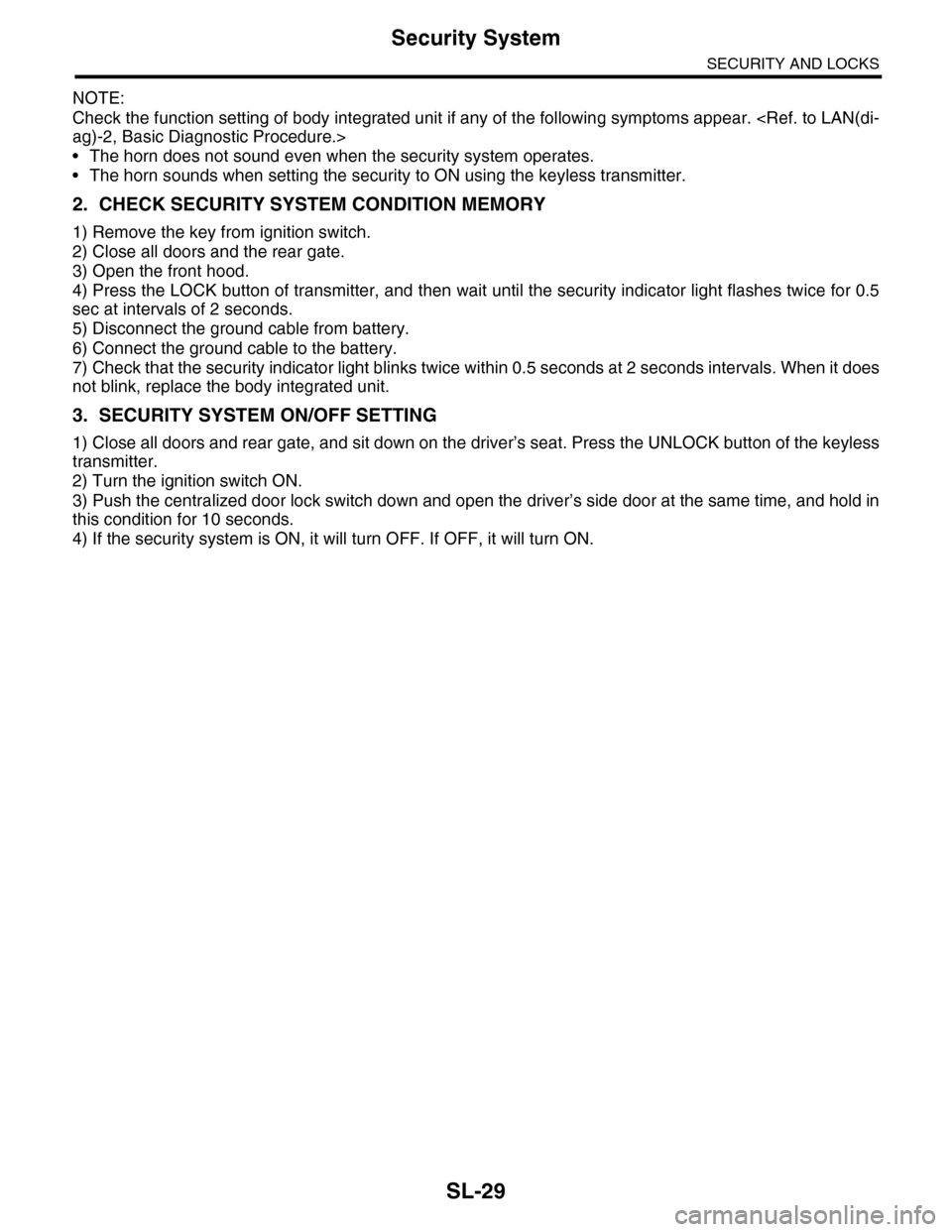
NOTE:
Check the function setting of body integrated unit if any of the following symptoms appear.
•The horn does not sound even when the security system operates.
•The horn sounds when setting the security to ON using the keyless transmitter.
2. CHECK SECURITY SYSTEM CONDITION MEMORY
1) Remove the key from ignition switch.
2) Close all doors and the rear gate.
3) Open the front hood.
4) Press the LOCK button of transmitter, and then wait until the security indicator light flashes twice for 0.5
sec at intervals of 2 seconds.
5) Disconnect the ground cable from battery.
6) Connect the ground cable to the battery.
7) Check that the security indicator light blinks twice within 0.5 seconds at 2 seconds intervals. When it does
not blink, replace the body integrated unit.
3. SECURITY SYSTEM ON/OFF SETTING
1) Close all doors and rear gate, and sit down on the driver’s seat. Press the UNLOCK button of the keyless
transmitter.
2) Turn the ignition switch ON.
3) Push the centralized door lock switch down and open the driver’s side door at the same time, and hold in
this condition for 10 seconds.
4) If the security system is ON, it will turn OFF. If OFF, it will turn ON.
Page 661 of 2453
SL-32
Security System
SECURITY AND LOCKS
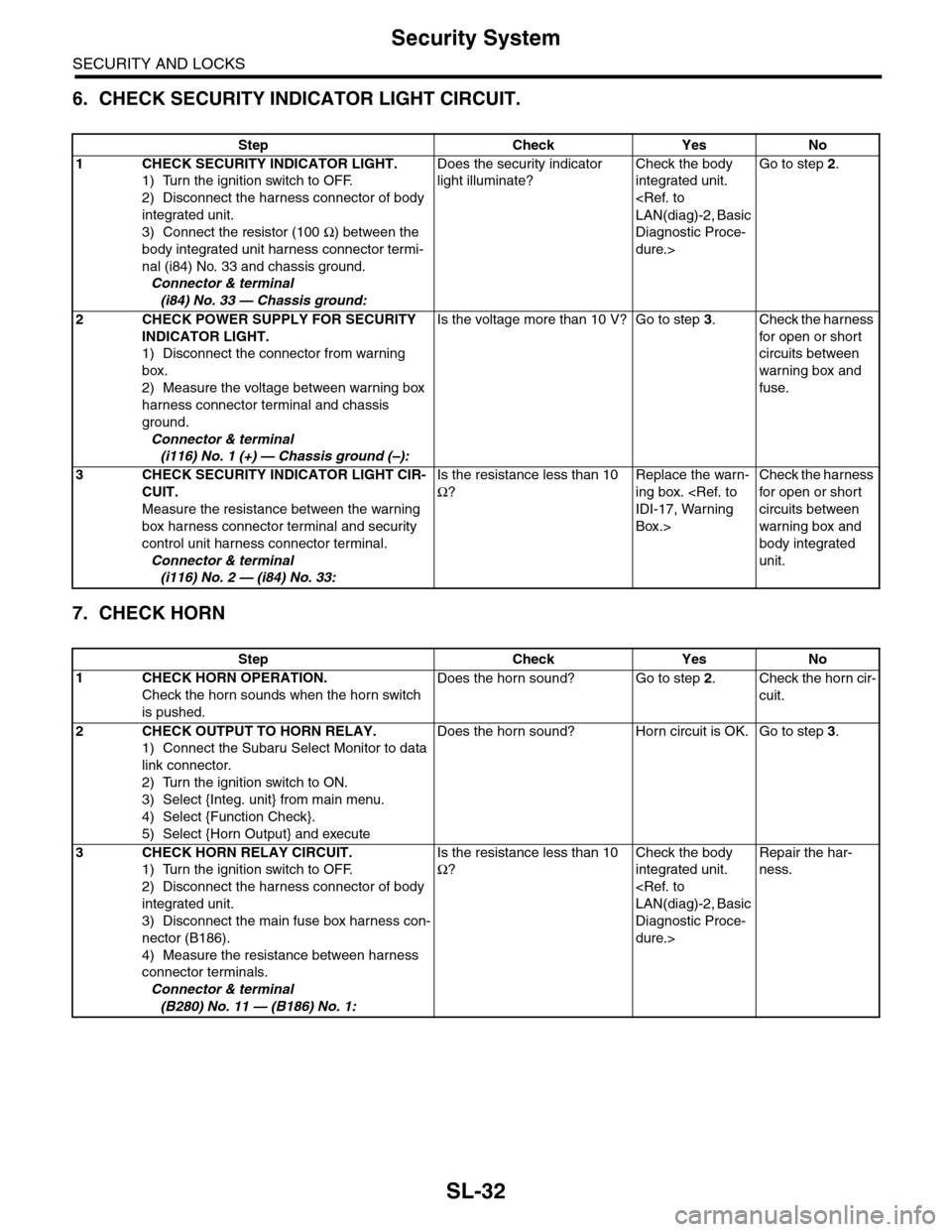
6. CHECK SECURITY INDICATOR LIGHT CIRCUIT.
7. CHECK HORN
Step Check Yes No
1CHECK SECURITY INDICATOR LIGHT.
1) Turn the ignition switch to OFF.
2) Disconnect the harness connector of body
integrated unit.
3) Connect the resistor (100 Ω) between the
body integrated unit harness connector termi-
nal (i84) No. 33 and chassis ground.
Connector & terminal
(i84) No. 33 — Chassis ground:
Does the security indicator
light illuminate?
Check the body
integrated unit.
Diagnostic Proce-
dure.>
Go to step 2.
2CHECK POWER SUPPLY FOR SECURITY
INDICATOR LIGHT.
1) Disconnect the connector from warning
box.
2) Measure the voltage between warning box
harness connector terminal and chassis
ground.
Connector & terminal
(i116) No. 1 (+) — Chassis ground (–):
Is the voltage more than 10 V? Go to step 3.Check the harness
for open or shor t
circuits between
warning box and
fuse.
3CHECK SECURITY INDICATOR LIGHT CIR-
CUIT.
Measure the resistance between the warning
box harness connector terminal and security
control unit harness connector terminal.
Connector & terminal
(i116) No. 2 — (i84) No. 33:
Is the resistance less than 10
Ω?
Replace the warn-
ing box.
Box.>
Check the harness
for open or shor t
circuits between
warning box and
body integrated
unit.
Step Check Yes No
1CHECK HORN OPERATION.
Check the horn sounds when the horn switch
is pushed.
Does the horn sound? Go to step 2.Check the horn cir-
cuit.
2CHECK OUTPUT TO HORN RELAY.
1) Connect the Subaru Select Monitor to data
link connector.
2) Turn the ignition switch to ON.
3) Select {Integ. unit} from main menu.
4) Select {Function Check}.
5) Select {Horn Output} and execute
Does the horn sound? Horn circuit is OK. Go to step 3.
3CHECK HORN RELAY CIRCUIT.
1) Turn the ignition switch to OFF.
2) Disconnect the harness connector of body
integrated unit.
3) Disconnect the main fuse box harness con-
nector (B186).
4) Measure the resistance between harness
connector terminals.
Connector & terminal
(B280) No. 11 — (B186) No. 1:
Is the resistance less than 10
Ω?
Check the body
integrated unit.
Diagnostic Proce-
dure.>
Repair the har-
ness.
Page 662 of 2453
SL-33
Security System
SECURITY AND LOCKS
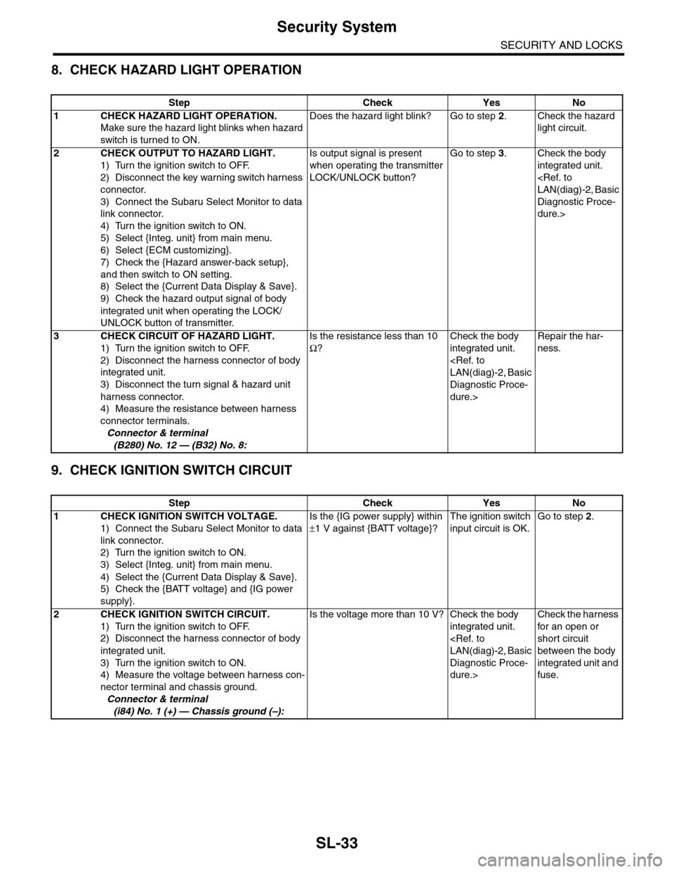
8. CHECK HAZARD LIGHT OPERATION
9. CHECK IGNITION SWITCH CIRCUIT
Step Check Yes No
1CHECK HAZARD LIGHT OPERATION.
Make sure the hazard light blinks when hazard
switch is turned to ON.
Does the hazard light blink? Go to step 2.Check the hazard
light circuit.
2CHECK OUTPUT TO HAZARD LIGHT.
1) Turn the ignition switch to OFF.
2) Disconnect the key warning switch harness
connector.
3) Connect the Subaru Select Monitor to data
link connector.
4) Turn the ignition switch to ON.
5) Select {Integ. unit} from main menu.
6) Select {ECM customizing}.
7) Check the {Hazard answer-back setup},
and then switch to ON setting.
8) Select the {Current Data Display & Save}.
9) Check the hazard output signal of body
integrated unit when operating the LOCK/
UNLOCK button of transmitter.
Is output signal is present
when operating the transmitter
LOCK/UNLOCK button?
Go to step 3.Check the body
integrated unit.
Diagnostic Proce-
dure.>
3CHECK CIRCUIT OF HAZARD LIGHT.
1) Turn the ignition switch to OFF.
2) Disconnect the harness connector of body
integrated unit.
3) Disconnect the turn signal & hazard unit
harness connector.
4) Measure the resistance between harness
connector terminals.
Connector & terminal
(B280) No. 12 — (B32) No. 8:
Is the resistance less than 10
Ω?
Check the body
integrated unit.
Diagnostic Proce-
dure.>
Repair the har-
ness.
Step Check Yes No
1CHECK IGNITION SWITCH VOLTAGE.
1) Connect the Subaru Select Monitor to data
link connector.
2) Turn the ignition switch to ON.
3) Select {Integ. unit} from main menu.
4) Select the {Current Data Display & Save}.
5) Check the {BATT voltage} and {IG power
supply}.
Is the {IG power supply} within
±1 V against {BATT voltage}?
The ignition switch
input circuit is OK.
Go to step 2.
2 CHECK IGNITION SWITCH CIRCUIT.
1) Turn the ignition switch to OFF.
2) Disconnect the harness connector of body
integrated unit.
3) Turn the ignition switch to ON.
4) Measure the voltage between harness con-
nector terminal and chassis ground.
Connector & terminal
(i84) No. 1 (+) — Chassis ground (–):
Is the voltage more than 10 V? Check the body
integrated unit.
Diagnostic Proce-
dure.>
Check the harness
for an open or
short circuit
between the body
integrated unit and
fuse.
Page 678 of 2453
SL-49
Impact Sensor
SECURITY AND LOCKS
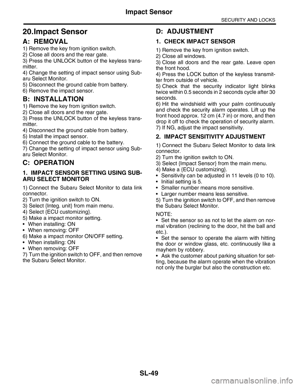
20.Impact Sensor
A: REMOVAL
1) Remove the key from ignition switch.
2) Close all doors and the rear gate.
3) Press the UNLOCK button of the keyless trans-
mitter.
4) Change the setting of impact sensor using Sub-
aru Select Monitor.
5) Disconnect the ground cable from battery.
6) Remove the impact sensor.
B: INSTALLATION
1) Remove the key from ignition switch.
2) Close all doors and the rear gate.
3) Press the UNLOCK button of the keyless trans-
mitter.
4) Disconnect the ground cable from battery.
5) Install the impact sensor.
6) Connect the ground cable to the battery.
7) Change the setting of impact sensor using Sub-
aru Select Monitor.
C: OPERATION
1. IMPACT SENSOR SETTING USING SUB-
ARU SELECT MONITOR
1) Connect the Subaru Select Monitor to data link
connector.
2) Turn the ignition switch to ON.
3) Select {Integ. unit} from main menu.
4) Select {ECU customizing}.
5) Make a impact monitor setting.
•When installing: ON
•When removing: OFF
6) Make a impact monitor ON/OFF setting.
•When installing: ON
•When removing: OFF
7) Turn the ignition switch to OFF, and then remove
the Subaru Select Monitor.
D: ADJUSTMENT
1. CHECK IMPACT SENSOR
1) Remove the key from ignition switch.
2) Close all windows.
3) Close all doors and the rear gate. Leave open
the front hood.
4) Press the LOCK button of the keyless transmit-
ter from outside of vehicle.
5) Check that the security indicator light blinks
twice within 0.5 seconds in 2 seconds cycle after 30
seconds.
6) Hit the windshield with your palm continuously
and check the security alarm operates. Lift up the
front hood approx. 12 cm (4.7 in) or more, and then
drop it off to check the operation of security alarm.
7) If NG, adjust the impact sensitivity.
2. IMPACT SENSITIVITY ADJUSTMENT
1) Connect the Subaru Select Monitor to data link
connector.
2) Turn the ignition switch to ON.
3) Select {Impact Sensor} from the main menu.
4) Make a {ECU customizing}.
•Sensitivity can be adjusted in 11 levels (0 to 10).
•Initial setting is 5.
•Smaller number means more sensitive.
•Larger number means less sensitive.
5) Turn the ignition switch to OFF, and then remove
the Subaru Select Monitor.
NOTE:
•Set the sensor so as not to let the alarm on nor-
mal vibration (reclining to the door, hit the ball and
etc.).
•Set the sensor to operate the alarm with hitting
the door or window glass, etc. continuously like a
mayhem by robbery.
•Ask the customer about parking situation for set-
ting, because the alarm operate when the vibration
not only the burglar but also the construction etc.
Page 684 of 2453
SL-55
Immobilizer Antenna
SECURITY AND LOCKS
26.Immobilizer Antenna
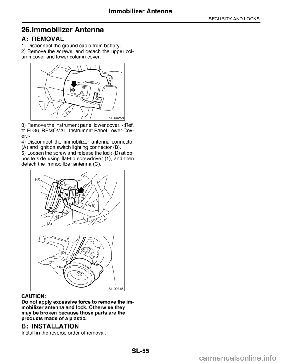
A: REMOVAL
1) Disconnect the ground cable from battery.
2) Remove the screws, and detach the upper col-
umn cover and lower column cover.
3) Remove the instrument panel lower cover.
er.>
4) Disconnect the immobilizer antenna connector
(A) and ignition switch lighting connector (B).
5) Loosen the screw and release the lock (D) at op-
posite side using flat-tip screwdriver (1), and then
detach the immobilizer antenna (C).
CAUTION:
Do not apply excessive force to remove the im-
mobilizer antenna and lock. Otherwise they
may be broken because those parts are the
products made of a plastic.
B: INSTALLATION
Install in the reverse order of removal.
SL-00258
(D)
(1)
SL-00315
(A)
(C)
(B)
Page 2358 of 2453
WI-74
Immobilizer System
WIRING SYSTEM
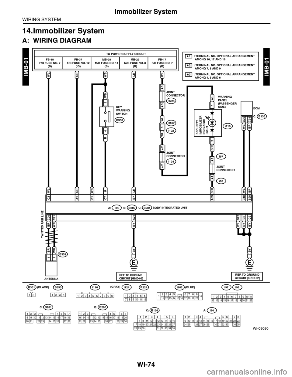
14.Immobilizer System
A: WIRING DIAGRAM
WI-08080
IMB-01IMB-01
BR
B351
12
B350
1234
A: i84
1234567891011121415161718192021222324252627282930313233343513
WLGRWBLRWL
FB-18F/B FUSE NO. 7(B)
FB-37F/B FUSE NO. 12(IG)
MB-28M/B FUSE NO. 14(B)
KEYWARNINGSWITCH
MB-29M/B FUSE NO. 8(B)
FB-17F/B FUSE NO. 7(B)
ECM
TO POWER SUPPLY CIRCUIT
C26C34B350
WB
R
4
WB
3
WL
C2
GR
A1
RWB
C7C1
LR
B7
BrR BrR
A33
BP
B28
WL
B18
BYBY
BY
C9
BY
C8
BY
B22
WLBP
A: i84B: B280C: B281B: B280
C20
WR
BRWR
C21
BY
A21
12
ANTENNA
BODY INTEGRATED UNIT
B351
WARNINGPANEL(PASSENGERSIDE)
SECURITYIMMOBILIZERINDICATORLIGHT
B136C:
2
56782194310242223 25111213141526 27 281617181920 21
B281C:
5467821931022 23111213141524 25 26 2716171828 29192021 30
B280B:
i116
REF. TO GROUNDCIRCUIT [GND-02]
(BLACK)
TWISTED PAIR LINE
JOINTCONNECTOR
i97
i98
1*
1*
JOINTCONNECTOR
R224
R167
i102
3*
3*
JOINTCONNECTOR
i124
2*
2*
1
WL
: TERMINAL NO. OPTIONAL ARRANGEMENT AMONG 16, 17 AND 18
: TERMINAL NO. OPTIONAL ARRANGEMENT AMONG 7, 8 AND 9
1*
2*
: TERMINAL NO. OPTIONAL ARRANGEMENT AMONG 4, 5 AND 63*
123456789101112
i124i98i97
12345678910111213141516171819202122
i116
12345678910
C: B136
16101112131415252430
9871718192028212223293231
123456
2726333435
R224
1234567891413121110151617181920
i102(BLUE)
5
WL
WL
REF. TO GROUNDCIRCUIT [GND-05]
(GRAY)
Page 2428 of 2453
WI-144
Security System
WIRING SYSTEM
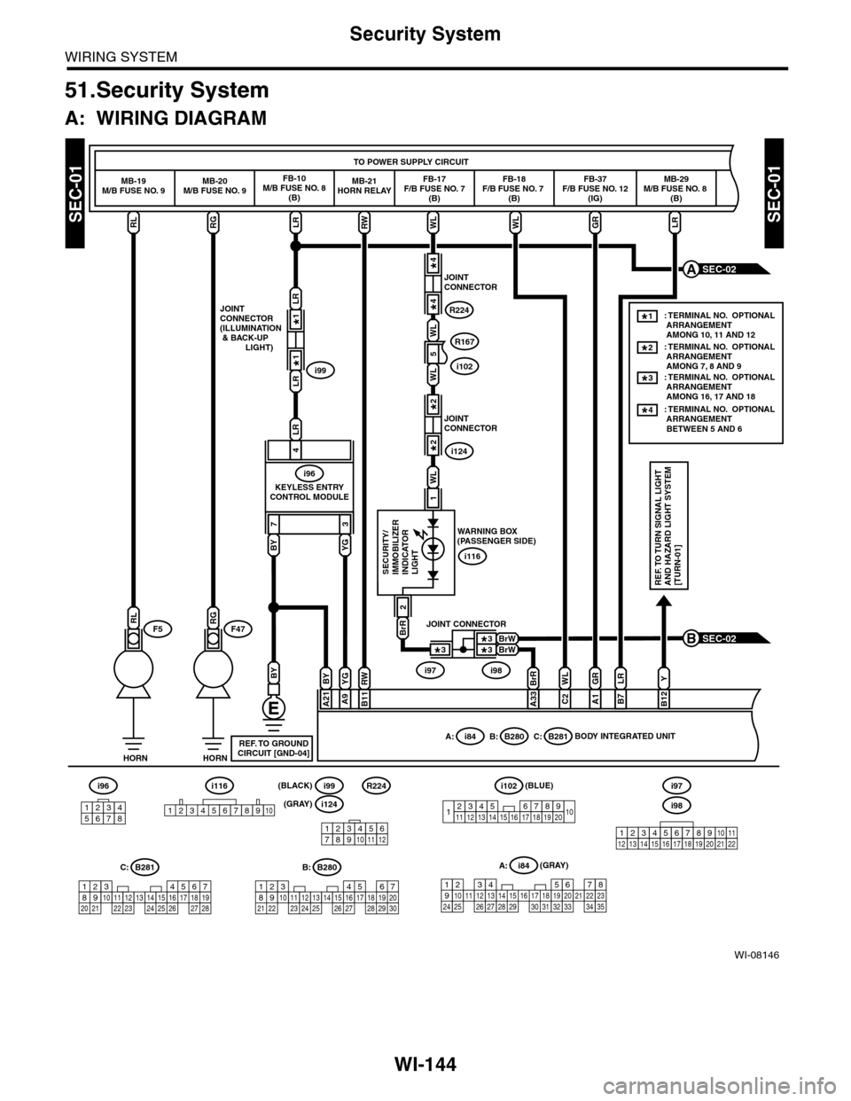
51.Security System
A: WIRING DIAGRAM
WI-08146
SEC-01SEC-01
SEC-02B
HORNHORN
F5F47
TO POWER SUPPLY CIRCUIT
MB-19M/B FUSE NO. 9MB-20M/B FUSE NO. 9FB-10M/B FUSE NO. 8(B)
FB-17F/B FUSE NO. 7(B)
FB-18F/B FUSE NO. 7 (B)
FB-37F/B FUSE NO. 12(IG)
MB-29M/B FUSE NO. 8 (B)
RGLRWLWLGRLRRL
73
LR
LR
JOINTCONNECTOR(ILLUMINATION & BACK-UP LIGHT)
KEYLESS ENTRYCONTROL MODULE
i99
LR
4
i96
BY
BYYG
A9
RW
B11
BY
A21
BrR
A33
WL
WL
R167
i102
WL
C2
GR
A1
LR
B7
Y
B12
BrR
2
1
SECURITY/IMMOBILIZERINDICATORLIGHTREF. TO TURN SIGNAL LIGHTAND HAZARD LIGHT SYSTEM[TURN-01]
BODY INTEGRATED UNITA: i84B: B280C: B281
WARNING BOX(PASSENGER SIDE)
i116YG
RW
RGRL
i96
12345678
567821943102422 23 25111213141526 27 281617181920 21
B281C:
5467821931022 23111213141524 25 26 2716171828 29192021 30
B280B:A: i84
1234567891011121415161718192021222324252627282930313233343513
REF. TO GROUNDCIRCUIT [GND-04]
SEC-02A
MB-21HORN RELAY
5
JOINTCONNECTOR
i124
2*
2*
1*
1*
JOINTCONNECTOR
R224
4*
4*
WL
BrWBrW
JOINT CONNECTOR
i97i98
3*
3*3*
: TERMINAL NO. OPTIONAL ARRANGEMENT AMONG 7, 8 AND 9: TERMINAL NO. OPTIONAL ARRANGEMENT AMONG 16, 17 AND 18
2*
: TERMINAL NO. OPTIONAL ARRANGEMENT AMONG 10, 11 AND 12
1*
3*
: TERMINAL NO. OPTIONAL ARRANGEMENT BETWEEN 5 AND 6
4*
1234567891413121110151617181920
i102(BLUE)
123456789101112
R224
i124(GRAY)
(GRAY)
i99(BLACK)i116
12345678910i98
i97
12345678910111213141516171819202122