checking oil SUBARU TRIBECA 2009 1.G Service Workshop Manual
[x] Cancel search | Manufacturer: SUBARU, Model Year: 2009, Model line: TRIBECA, Model: SUBARU TRIBECA 2009 1.GPages: 2453, PDF Size: 46.32 MB
Page 4 of 2453
AB-5
General Description
AIRBAG SYSTEM
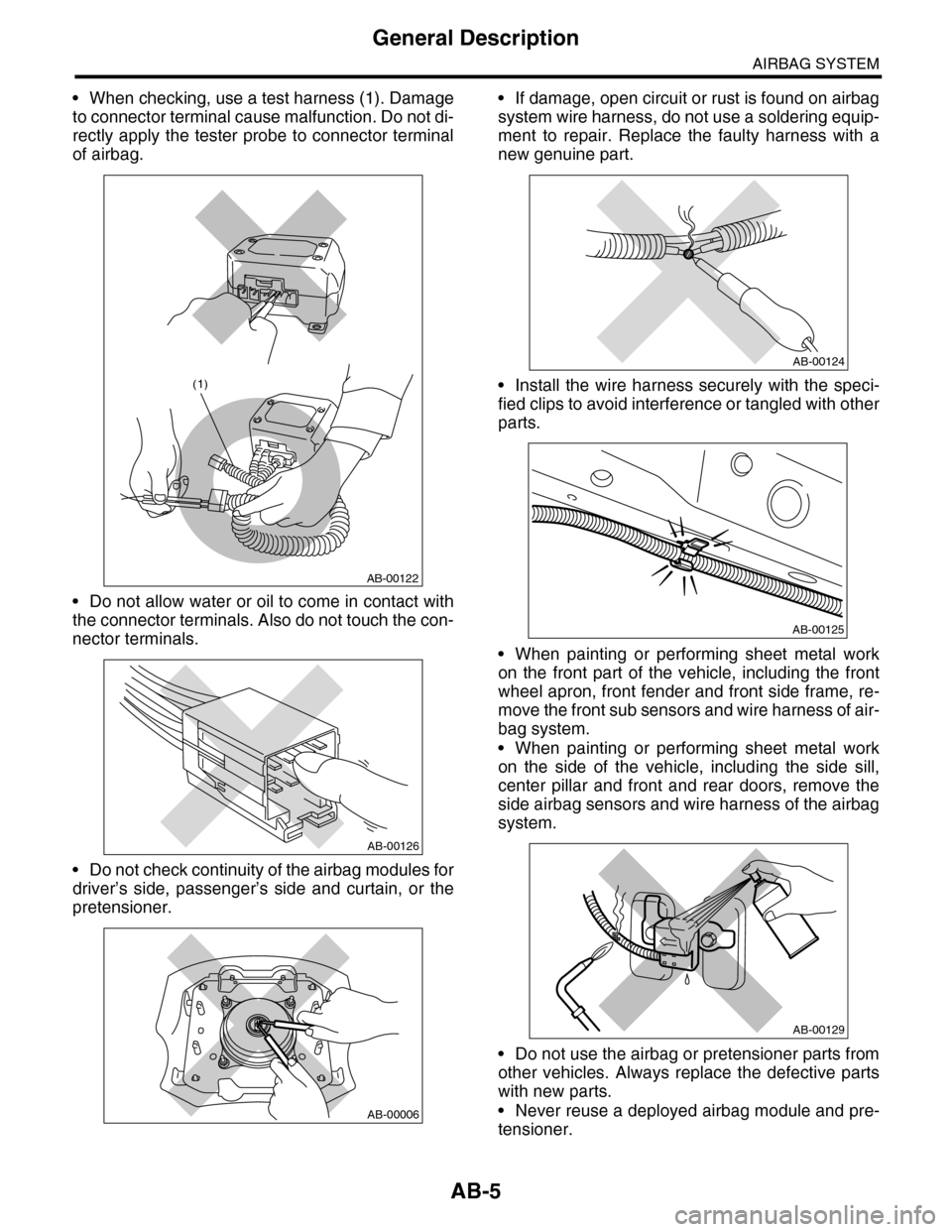
•When checking, use a test harness (1). Damage
to connector terminal cause malfunction. Do not di-
rectly apply the tester probe to connector terminal
of airbag.
•Do not allow water or oil to come in contact with
the connector terminals. Also do not touch the con-
nector terminals.
•Do not check continuity of the airbag modules for
driver’s side, passenger’s side and curtain, or the
pretensioner.
•If damage, open circuit or rust is found on airbag
system wire harness, do not use a soldering equip-
ment to repair. Replace the faulty harness with a
new genuine part.
•Install the wire harness securely with the speci-
fied clips to avoid interference or tangled with other
parts.
•When painting or performing sheet metal work
on the front part of the vehicle, including the front
wheel apron, front fender and front side frame, re-
move the front sub sensors and wire harness of air-
bag system.
•When painting or performing sheet metal work
on the side of the vehicle, including the side sill,
center pillar and front and rear doors, remove the
side airbag sensors and wire harness of the airbag
system.
•Do not use the airbag or pretensioner parts from
other vehicles. Always replace the defective parts
with new parts.
•Never reuse a deployed airbag module and pre-
tensioner.
AB-00122
(1)
AB-00126
AB-00006
AB-00124
AB-00125
AB-00129
Page 28 of 2453
AB(diag)-4
General Description
AIRBAG SYSTEM (DIAGNOSTICS)
3. General Description
A: CAUTION
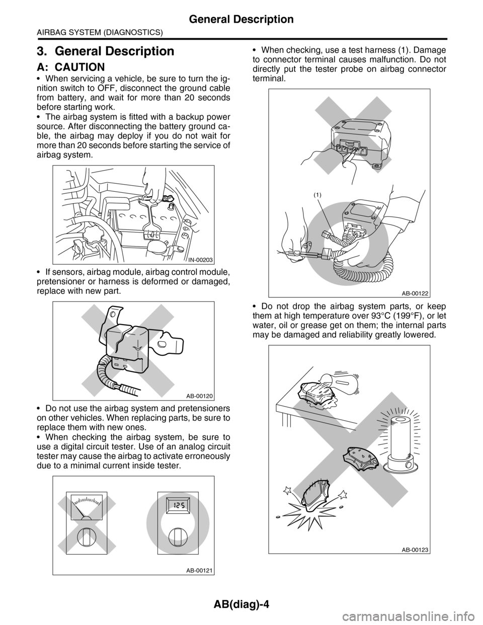
•When servicing a vehicle, be sure to turn the ig-
nition switch to OFF, disconnect the ground cable
from battery, and wait for more than 20 seconds
before starting work.
•The airbag system is fitted with a backup power
source. After disconnecting the battery ground ca-
ble, the airbag may deploy if you do not wait for
more than 20 seconds before starting the service of
airbag system.
•If sensors, airbag module, airbag control module,
pretensioner or harness is deformed or damaged,
replace with new part.
•Do not use the airbag system and pretensioners
on other vehicles. When replacing parts, be sure to
replace them with new ones.
•When checking the airbag system, be sure to
use a digital circuit tester. Use of an analog circuit
tester may cause the airbag to activate erroneously
due to a minimal current inside tester.
•When checking, use a test harness (1). Damage
to connector terminal causes malfunction. Do not
directly put the tester probe on airbag connector
terminal.
•Do not drop the airbag system parts, or keep
them at high temperature over 93°C (199°F), or let
water, oil or grease get on them; the internal parts
may be damaged and reliability greatly lowered.
IN-00203
AB-00120
AB-00121
AB-00122
(1)
AB-00123
Page 204 of 2453
ET-19
Antenna
ENTERTAINMENT
14.Antenna
A: INSPECTION
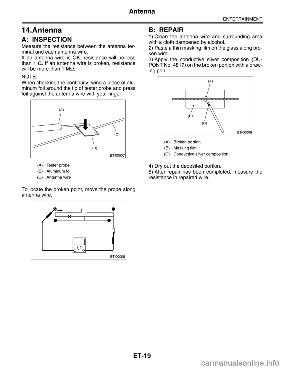
Measure the resistance between the antenna ter-
minal and each antenna wire.
If an antenna wire is OK, resistance will be less
than 1 Ω. If an antenna wire is broken, resistance
will be more than 1 MΩ.
NOTE:
When checking the continuity, wind a piece of alu-
minum foil around the tip of tester probe and press
foil against the antenna wire with your finger.
To locate the broken point, move the probe along
antenna wire.
B: REPAIR
1) Clean the antenna wire and surrounding area
with a cloth dampened by alcohol.
2) Paste a thin masking film on the glass along bro-
ken wire.
3) Apply the conductive silver composition (DU-
PONT No. 4817) on the broken portion with a draw-
ing pen.
4) Dry out the deposited portion.
5) After repair has been completed, measure the
resistance in repaired wire.
(A) Tester probe
(B) Aluminum foil
(C) Antenna wire
ET-00007
(B)
(C)
(A)
ET-00008
(A) Broken portion
(B) Masking film
(C) Conductive silver composition
ET-00009
(B)
(C)
(A)
Page 818 of 2453
DI-34
General Diagnostic Table
DIFFERENTIALS
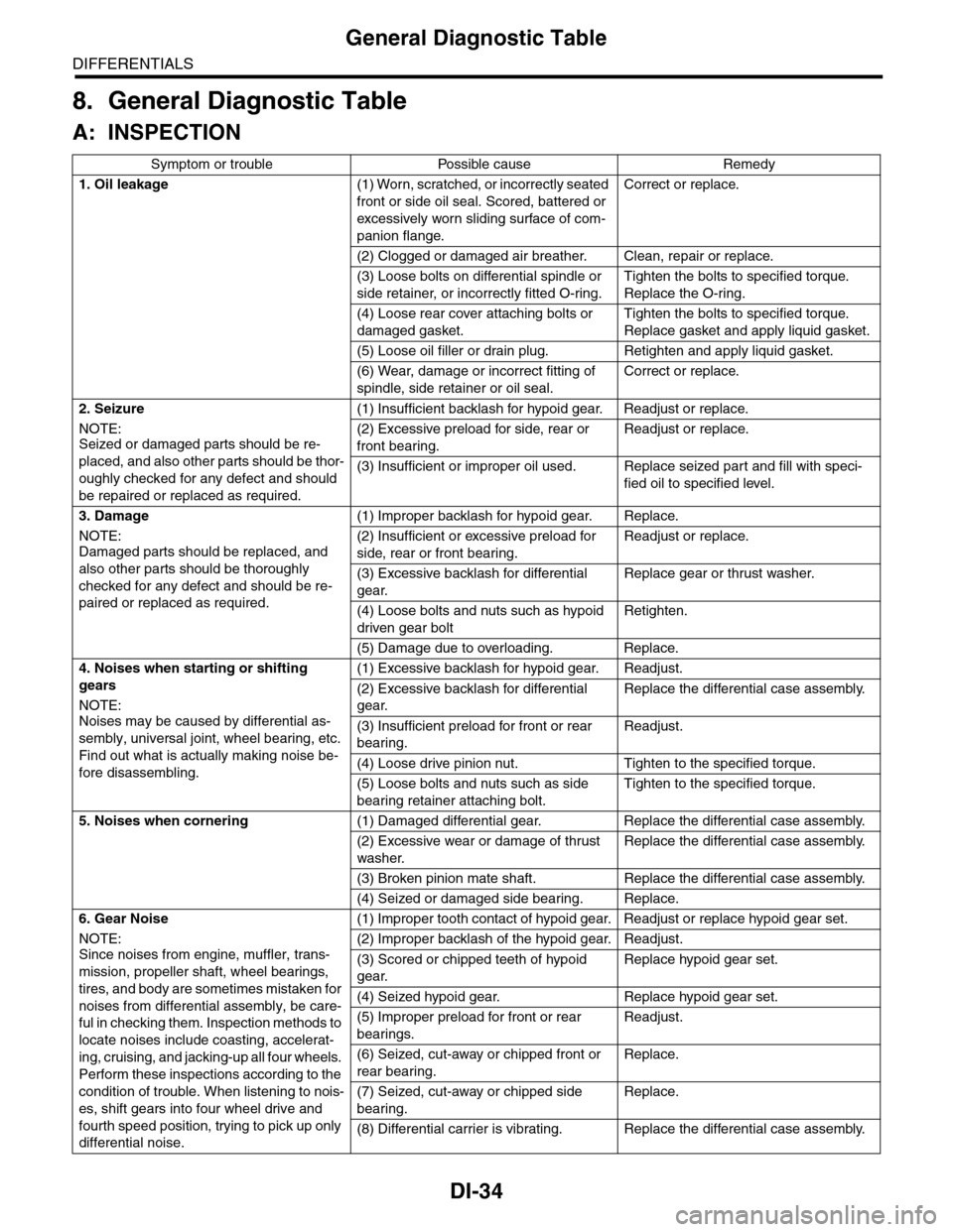
8. General Diagnostic Table
A: INSPECTION
Symptom or trouble Possible cause Remedy
1. Oil leakage(1) Worn, scratched, or incorrectly seated
front or side oil seal. Scored, battered or
excessively wor n sliding surface of com-
panion flange.
Correct or replace.
(2) Clogged or damaged air breather. Clean, repair or replace.
(3) Loose bolts on differential spindle or
side retainer, or incorrectly fitted O-ring.
Tighten the bolts to specified torque.
Replace the O-ring.
(4) Loose rear cover attaching bolts or
damaged gasket.
Tighten the bolts to specified torque.
Replace gasket and apply liquid gasket.
(5) Loose oil filler or drain plug. Retighten and apply liquid gasket.
(6) Wear, damage or incorrect fitting of
spindle, side retainer or oil seal.
Correct or replace.
2. Seizure
NOTE:Seized or damaged parts should be re-
placed, and also other parts should be thor-
oughly checked for any defect and should
be repaired or replaced as required.
(1) Insufficient backlash for hypoid gear. Readjust or replace.
(2) Excessive preload for side, rear or
front bearing.
Readjust or replace.
(3) Insufficient or improper oil used. Replace seized part and fill with speci-
fied oil to specified level.
3. Damage
NOTE:Damaged parts should be replaced, and
also other parts should be thoroughly
checked for any defect and should be re-
paired or replaced as required.
(1) Improper backlash for hypoid gear. Replace.
(2) Insufficient or excessive preload for
side, rear or front bearing.
Readjust or replace.
(3) Excessive backlash for differential
gear.
Replace gear or thrust washer.
(4) Loose bolts and nuts such as hypoid
driven gear bolt
Retighten.
(5) Damage due to overloading. Replace.
4. Noises when starting or shifting
gears
NOTE:
Noises may be caused by differential as-
sembly, universal joint, wheel bearing, etc.
Find out what is actually making noise be-
fore disassembling.
(1) Excessive backlash for hypoid gear. Readjust.
(2) Excessive backlash for differential
gear.
Replace the differential case assembly.
(3) Insufficient preload for front or rear
bearing.
Readjust.
(4) Loose drive pinion nut. Tighten to the specified torque.
(5) Loose bolts and nuts such as side
bearing retainer attaching bolt.
Tighten to the specified torque.
5. Noises when cornering(1) Damaged differential gear. Replace the differential case assembly.
(2) Excessive wear or damage of thrust
washer.
Replace the differential case assembly.
(3) Broken pinion mate shaft. Replace the differential case assembly.
(4) Seized or damaged side bearing. Replace.
6. Gear Noise
NOTE:
Since noises from engine, muffler, trans-
mission, propeller shaft, wheel bearings,
tires, and body are sometimes mistaken for
noises from differential assembly, be care-
ful in checking them. Inspection methods to
locate noises include coasting, accelerat-
ing, cruising, and jacking-up all four wheels.
Perform these inspections according to the
condition of trouble. When listening to nois-
es, shift gears into four wheel drive and
fourth speed position, trying to pick up only
differential noise.
(1) Improper tooth contact of hypoid gear. Readjust or replace hypoid gear set.
(2) Improper backlash of the hypoid gear. Readjust.
(3) Scored or chipped teeth of hypoid
gear.
Replace hypoid gear set.
(4) Seized hypoid gear. Replace hypoid gear set.
(5) Improper preload for front or rear
bearings.
Readjust.
(6) Seized, cut-away or chipped front or
rear bearing.
Replace.
(7) Seized, cut-away or chipped side
bearing.
Replace.
(8) Differential carrier is vibrating. Replace the differential case assembly.
Page 868 of 2453
FS-20
Front Strut
FRONT SUSPENSION
C: DISASSEMBLY
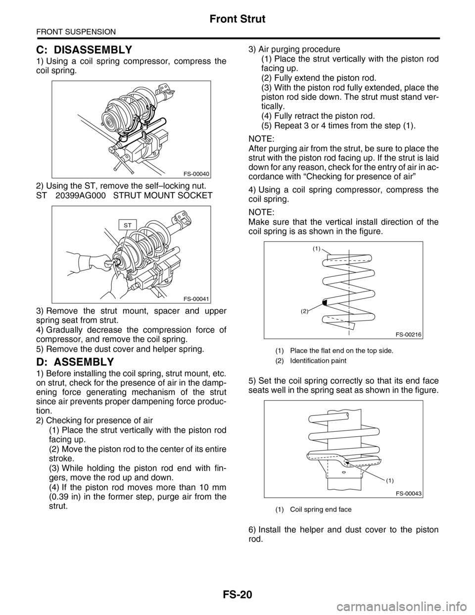
1) Using a coil spring compressor, compress the
coil spring.
2) Using the ST, remove the self–locking nut.
ST 20399AG000 STRUT MOUNT SOCKET
3) Remove the strut mount, spacer and upper
spring seat from strut.
4) Gradually decrease the compression force of
compressor, and remove the coil spring.
5) Remove the dust cover and helper spring.
D: ASSEMBLY
1) Before installing the coil spring, strut mount, etc.
on strut, check for the presence of air in the damp-
ening force generating mechanism of the strut
since air prevents proper dampening force produc-
tion.
2) Checking for presence of air
(1) Place the strut vertically with the piston rod
facing up.
(2) Move the piston rod to the center of its entire
stroke.
(3) While holding the piston rod end with fin-
gers, move the rod up and down.
(4) If the piston rod moves more than 10 mm
(0.39 in) in the former step, purge air from the
strut.
3) Air purging procedure
(1) Place the strut vertically with the piston rod
facing up.
(2) Fully extend the piston rod.
(3) With the piston rod fully extended, place the
piston rod side down. The strut must stand ver-
tically.
(4) Fully retract the piston rod.
(5) Repeat 3 or 4 times from the step (1).
NOTE:
After purging air from the strut, be sure to place the
strut with the piston rod facing up. If the strut is laid
down for any reason, check for the entry of air in ac-
cordance with “Checking for presence of air”
4) Using a coil spring compressor, compress the
coil spring.
NOTE:
Make sure that the vertical install direction of the
coil spring is as shown in the figure.
5) Set the coil spring correctly so that its end face
seats well in the spring seat as shown in the figure.
6) Install the helper and dust cover to the piston
rod.
FS-00040
FS-00041
ST
(1) Place the flat end on the top side.
(2) Identification paint
(1) Coil spring end face
FS-00216
(2)
(1)
FS-00043
(1)
Page 1089 of 2453
VDC-8
VDC Control Module & Hydraulic Control Unit (VDCCM&H/U)
VEHICLE DYNAMICS CONTROL (VDC)
4) Connect the VDCCM&H/U connectors.
NOTE:
•Be sure to remove all foreign matter from inside
the connector before connecting.
•Make sure the VDCCM&H/U connector is se-
curely locked.
5) Bleed air from the brake system.
C: INSPECTION
1) Check the condition of connection and settle-
ment of connector.
2) Check the mark used for VDCCM&H/U identifi-
cation.
Refer to “SPECIFICATION” for the identification
mark.
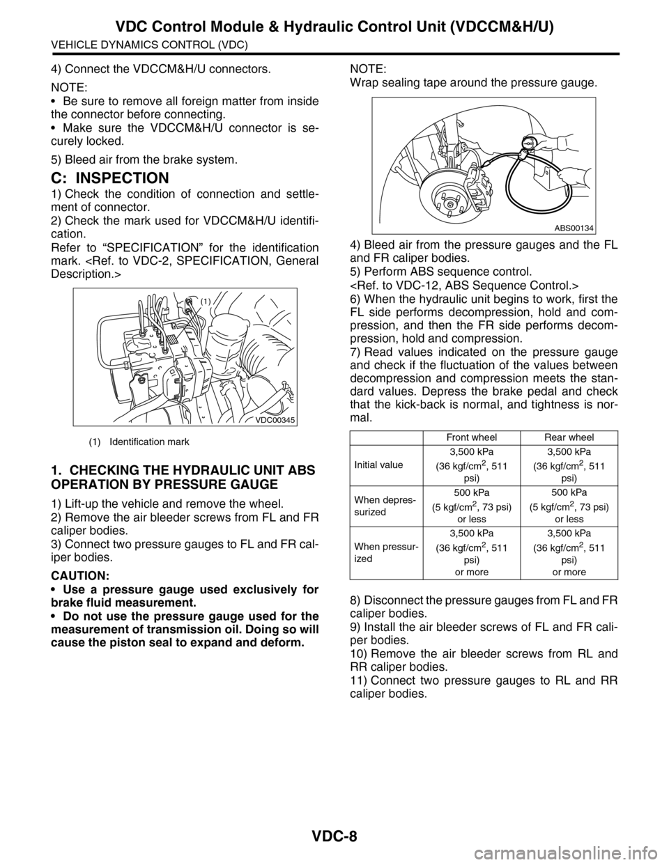
1. CHECKING THE HYDRAULIC UNIT ABS
OPERATION BY PRESSURE GAUGE
1) Lift-up the vehicle and remove the wheel.
2) Remove the air bleeder screws from FL and FR
caliper bodies.
3) Connect two pressure gauges to FL and FR cal-
iper bodies.
CAUTION:
•Use a pressure gauge used exclusively for
brake fluid measurement.
•Do not use the pressure gauge used for the
measurement of transmission oil. Doing so will
cause the piston seal to expand and deform.
NOTE:
Wrap sealing tape around the pressure gauge.
4) Bleed air from the pressure gauges and the FL
and FR caliper bodies.
5) Perform ABS sequence control.
6) When the hydraulic unit begins to work, first the
FL side performs decompression, hold and com-
pression, and then the FR side performs decom-
pression, hold and compression.
7) Read values indicated on the pressure gauge
and check if the fluctuation of the values between
decompression and compression meets the stan-
dard values. Depress the brake pedal and check
that the kick-back is normal, and tightness is nor-
mal.
8) Disconnect the pressure gauges from FL and FR
caliper bodies.
9) Install the air bleeder screws of FL and FR cali-
per bodies.
10) Remove the air bleeder screws from RL and
RR caliper bodies.
11) Connect two pressure gauges to RL and RR
caliper bodies.
(1) Identification mark
VDC00345
(1)
Front wheelRear wheel
Initial value
3,500 kPa
(36 kgf/cm2, 511
psi)
3,500 kPa
(36 kgf/cm2, 511
psi)
When depres-
surized
500 kPa
(5 kgf/cm2, 73 psi)
or less
500 kPa
(5 kgf/cm2, 73 psi)
or less
When pressur-
ized
3,500 kPa
(36 kgf/cm2, 511
psi)
or more
3,500 kPa
(36 kgf/cm2, 511
psi)
or more
ABS00134
Page 1090 of 2453
VDC-9
VDC Control Module & Hydraulic Control Unit (VDCCM&H/U)
VEHICLE DYNAMICS CONTROL (VDC)
12) Bleed air from the brake system.
13) Bleed air from RL and RR caliper bodies, and
pressure gauge.
14) Perform ABS sequence control.
15) When the hydraulic unit begins to work, first the
RR side performs decompression, hold and com-
pression, and then the RL side performs decom-
pression, hold and compression.
16) Read values indicated on the pressure gauge
and check if the fluctuation of the values between
decompression and compression meets specifica-
tion. Depress the brake pedal and check that the
kick-back is normal, and tightness is normal.
17) Disconnect the pressure gauge from the RL
and RR caliper bodies.
18) Install the air bleeder screws of RL and RR cal-
iper bodies.
19) Bleed air from the brake system.
2. CHECKING THE HYDRAULIC UNIT ABS
OPERATION WITH THE BRAKE TESTER
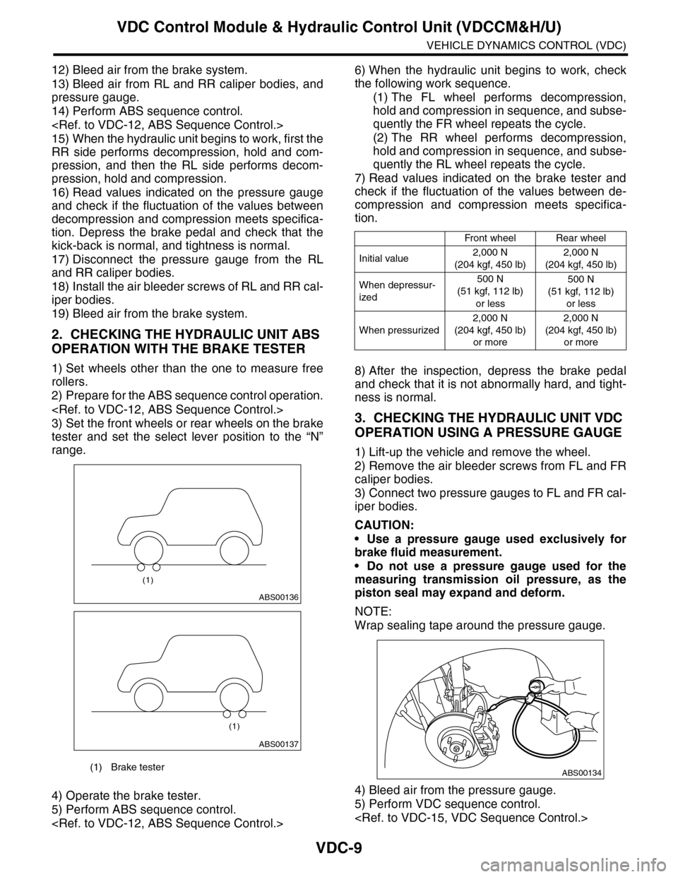
1) Set wheels other than the one to measure free
rollers.
2) Prepare for the ABS sequence control operation.
3) Set the front wheels or rear wheels on the brake
tester and set the select lever position to the “N”
range.
4) Operate the brake tester.
5) Perform ABS sequence control.
6) When the hydraulic unit begins to work, check
the following work sequence.
(1) The FL wheel performs decompression,
hold and compression in sequence, and subse-
quently the FR wheel repeats the cycle.
(2) The RR wheel performs decompression,
hold and compression in sequence, and subse-
quently the RL wheel repeats the cycle.
7) Read values indicated on the brake tester and
check if the fluctuation of the values between de-
compression and compression meets specifica-
tion.
8) After the inspection, depress the brake pedal
and check that it is not abnormally hard, and tight-
ness is normal.
3. CHECKING THE HYDRAULIC UNIT VDC
OPERATION USING A PRESSURE GAUGE
1) Lift-up the vehicle and remove the wheel.
2) Remove the air bleeder screws from FL and FR
caliper bodies.
3) Connect two pressure gauges to FL and FR cal-
iper bodies.
CAUTION:
•Use a pressure gauge used exclusively for
brake fluid measurement.
•Do not use a pressure gauge used for the
measuring transmission oil pressure, as the
piston seal may expand and deform.
NOTE:
Wrap sealing tape around the pressure gauge.
4) Bleed air from the pressure gauge.
5) Perform VDC sequence control.
(1) Brake tester
ABS00136
(1)
ABS00137
(1)
Front wheelRear wheel
Initial value2,000 N
(204 kgf, 450 lb)
2,000 N
(204 kgf, 450 lb)
When depressur-
ized
500 N
(51 kgf, 112 lb)
or less
500 N
(51 kgf, 112 lb)
or less
When pressurized
2,000 N
(204 kgf, 450 lb)
or more
2,000 N
(204 kgf, 450 lb)
or more
ABS00134
Page 1856 of 2453
LU(H6DO)-7
Engine Oil
LUBRICATION
3. Engine Oil
A: INSPECTION
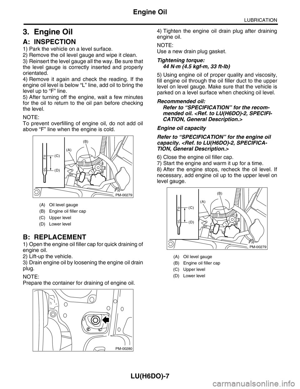
1) Park the vehicle on a level surface.
2) Remove the oil level gauge and wipe it clean.
3) Reinsert the level gauge all the way. Be sure that
the level gauge is correctly inserted and properly
orientated.
4) Remove it again and check the reading. If the
engine oil level is below “L” line, add oil to bring the
level up to “F” line.
5) After turning off the engine, wait a few minutes
for the oil to return to the oil pan before checking
the level.
NOTE:
To prevent overfilling of engine oil, do not add oil
above “F” line when the engine is cold.
B: REPLACEMENT
1) Open the engine oil filler cap for quick draining of
engine oil.
2) Lift-up the vehicle.
3) Drain engine oil by loosening the engine oil drain
plug.
NOTE:
Prepare the container for draining of engine oil.
4) Tighten the engine oil drain plug after draining
engine oil.
NOTE:
Use a new drain plug gasket.
Tightening torque:
44 N·m (4.5 kgf-m, 33 ft-lb)
5) Using engine oil of proper quality and viscosity,
fill engine oil through the oil filler duct to the upper
level on level gauge. Make sure that the vehicle is
parked on a level surface when checking oil level.
Recommended oil:
Refer to “SPECIFICATION” for the recom-
mended oil.
Engine oil capacity
Refer to “SPECIFICATION” for the engine oil
capacity.
6) Close the engine oil filler cap.
7) Start the engine and warm it up for a time.
8) After the engine stops, recheck the oil level. If
necessary, add engine oil up to the upper level on
level gauge.
(A) Oil level gauge
(B) Engine oil filler cap
(C) Upper level
(D) Lower level
PM-00279
(A)
(B)
(C)
(D)
PM-00280
(A) Oil level gauge
(B) Engine oil filler cap
(C) Upper level
(D) Lower level
PM-00279
(A)
(B)
(C)
(D)
Page 1936 of 2453
ME(H6DO)-70
Cylinder Block
MECHANICAL
D: ASSEMBLY
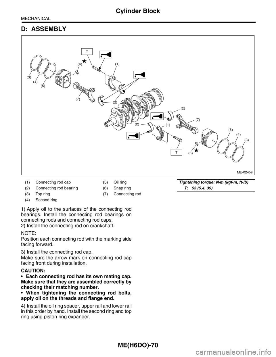
1) Apply oil to the surfaces of the connecting rod
bearings. Install the connecting rod bearings on
connecting rods and connecting rod caps.
2) Install the connecting rod on crankshaft.
NOTE:
Position each connecting rod with the marking side
facing forward.
3) Install the connecting rod cap.
Make sure the arrow mark on connecting rod cap
facing front during installation.
CAUTION:
•Each connecting rod has its own mating cap.
Make sure that they are assembled correctly by
checking their matching number.
•When tightening the connecting rod bolts,
apply oil on the threads and flange end.
4) Install the oil ring spacer, upper rail and lower rail
in this order by hand. Install the second ring and top
ring using piston ring expander.
(1) Connecting rod cap (5) Oil ringTightening torque: N·m (kgf-m, ft-lb)
(2) Connecting rod bearing (6) Snap ringT: 53 (5.4, 39)
(3) Top ring (7) Connecting rod
(4) Second ring
(1)
(1)
(2)
(2)
(2)
(7)
(3)
(4)(5)
(7)
(3)
(4)
(5)
(6)
(6)T
T
ME-02459
Page 1980 of 2453
SC(H6DO)-22
Generator
STARTING/CHARGING SYSTEMS
D: ASSEMBLY
Assemble in the reverse order of disassembly.
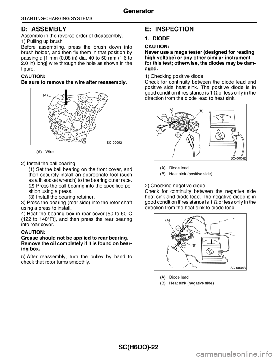
1) Pulling up brush
Before assembling, press the brush down into
brush holder, and then fix them in that position by
passing a [1 mm (0.08 in) dia. 40 to 50 mm (1.6 to
2.0 in) long] wire through the hole as shown in the
figure.
CAUTION:
Be sure to remove the wire after reassembly.
2) Install the ball bearing.
(1) Set the ball bearing on the front cover, and
then securely install an appropriate tool (such
as a fit socket wrench) to the bearing outer race.
(2) Press the ball bearing into the specified po-
sition using a press.
(3) Install the bearing retainer.
3) Press the bearing (rear side) into the rotor shaft
using a press to install.
4) Heat the bearing box in rear cover [50 to 60°C
(122 to 140°F)], and then press the rear bearing
into rear cover.
CAUTION:
Grease should not be applied to rear bearing.
Remove the oil completely if it is found on bear-
ing box.
5) After reassembly, turn the pulley by hand to
check that rotor turns smoothly.
E: INSPECTION
1. DIODE
CAUTION:
Never use a mega tester (designed for reading
high voltage) or any other similar instrument
for this test; otherwise, the diodes may be dam-
aged.
1) Checking positive diode
Check for continuity between the diode lead and
positive side heat sink. The positive diode is in
good condition if resistance is 1 Ω o r l e s s o n l y i n t h e
direction from the diode lead to heat sink.
2) Checking negative diode
Check for continuity between the negative side
heat sink and diode lead. The negative diode is in
good condition if resistance is 1 Ω o r l e s s o n l y i n t h e
direction from the heat sink to diode lead.
(A) Wire
SC-00092
(A)
(A) Diode lead
(B) Heat sink (positive side)
(A) Diode lead
(B) Heat sink (negative side)
SC-00042
(B)(A)
(A)
(B)
SC-00043