stop start SUBARU TRIBECA 2009 1.G Service Owner's Manual
[x] Cancel search | Manufacturer: SUBARU, Model Year: 2009, Model line: TRIBECA, Model: SUBARU TRIBECA 2009 1.GPages: 2453, PDF Size: 46.32 MB
Page 1098 of 2453
VDC-17
VDC Sequence Control
VEHICLE DYNAMICS CONTROL (VDC)
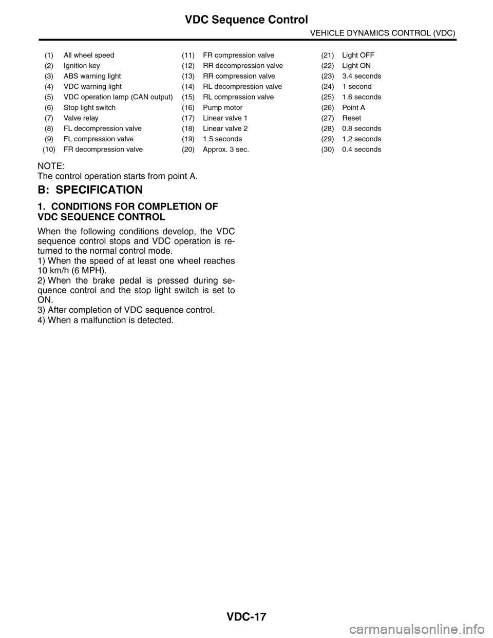
NOTE:
The control operation starts from point A.
B: SPECIFICATION
1. CONDITIONS FOR COMPLETION OF
VDC SEQUENCE CONTROL
When the following conditions develop, the VDC
sequence control stops and VDC operation is re-
turned to the normal control mode.
1) When the speed of at least one wheel reaches
10 km/h (6 MPH).
2) When the brake pedal is pressed during se-
quence control and the stop light switch is set to
ON.
3) After completion of VDC sequence control.
4) When a malfunction is detected.
(1) All wheel speed (11) FR compression valve (21) Light OFF
(2) Ignition key (12) RR decompression valve (22) Light ON
(3) ABS warning light (13) RR compression valve (23) 3.4 seconds
(4) VDC warning light (14) RL decompression valve (24) 1 second
(5) VDC operation lamp (CAN output) (15) RL compression valve (25) 1.6 seconds
(6) Stop light switch (16) Pump motor (26) Point A
(7) Valve relay (17) Linear valve 1 (27) Reset
(8) FL decompression valve (18) Linear valve 2 (28) 0.8 seconds
(9) FL compression valve (19) 1.5 seconds (29) 1.2 seconds
(10) FR decompression valve (20) Approx. 3 sec. (30) 0.4 seconds
Page 1129 of 2453
CO(H6DO)-10
Engine Coolant
COOLING
3. Engine Coolant
A: REPLACEMENT
1. DRAINING OF ENGINE COOLANT
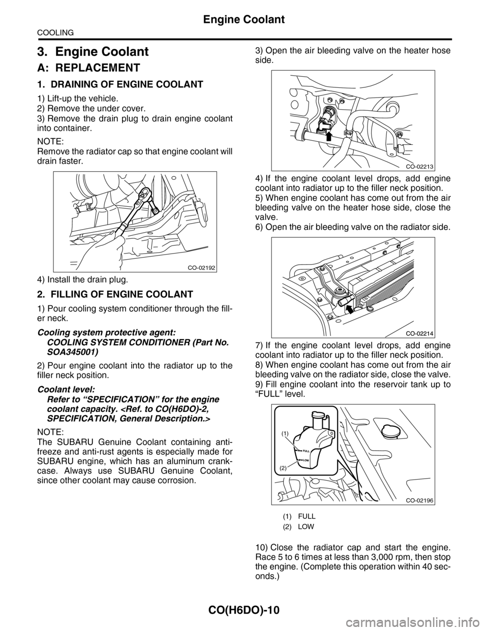
1) Lift-up the vehicle.
2) Remove the under cover.
3) Remove the drain plug to drain engine coolant
into container.
NOTE:
Remove the radiator cap so that engine coolant will
drain faster.
4) Install the drain plug.
2. FILLING OF ENGINE COOLANT
1) Pour cooling system conditioner through the fill-
er neck.
Cooling system protective agent:
COOLING SYSTEM CONDITIONER (Part No.
SOA345001)
2) Pour engine coolant into the radiator up to the
filler neck position.
Coolant level:
Refer to “SPECIFICATION” for the engine
coolant capacity.
NOTE:
The SUBARU Genuine Coolant containing anti-
freeze and anti-rust agents is especially made for
SUBARU engine, which has an aluminum crank-
case. Always use SUBARU Genuine Coolant,
since other coolant may cause corrosion.
3) Open the air bleeding valve on the heater hose
side.
4) If the engine coolant level drops, add engine
coolant into radiator up to the filler neck position.
5) When engine coolant has come out from the air
bleeding valve on the heater hose side, close the
valve.
6) Open the air bleeding valve on the radiator side.
7) If the engine coolant level drops, add engine
coolant into radiator up to the filler neck position.
8) When engine coolant has come out from the air
bleeding valve on the radiator side, close the valve.
9) Fill engine coolant into the reservoir tank up to
“FULL” level.
10) Close the radiator cap and start the engine.
Race 5 to 6 times at less than 3,000 rpm, then stop
the engine. (Complete this operation within 40 sec-
onds.)
CO-02192
(1) FULL
(2) LOW
CO-02213
CO-02196
(1)
(2)
Page 1130 of 2453
CO(H6DO)-11
Engine Coolant
COOLING
11) Wait for one minute after the engine stops,
open the radiator cap. If the engine coolant level
drops, add engine coolant into radiator up to the fill-
er neck position.
12) Perform the procedures 10) and 11) again.
13) Attach the radiator cap and reservoir tank cap
properly.
14) Start the engine and operate the heater at max-
imum hot position and the blower speed setting to
“LO.”
15) Run the engine at 2,000 rpm or less until radia-
tor fan starts and stops.
NOTE:
•Be careful with the engine coolant temperature
gauge to prevent overheating.
•If the radiator hose becomes harden with the
pressure of engine coolant, air bleeding operation
seems to be almost completed.
16) Stop the engine and wait until the engine cool-
ant temperature lowers to 30°C (86°F).
17) Open the radiator cap. If the engine coolant lev-
el drops, add engine coolant into radiator up to the
filler neck position and reservoir tank to the “FULL”
level.
18) Attach the radiator cap and reservoir tank cap
properly.
19) Set the heater setting to maximum hot position
and the blower speed setting to “LO” and start the
engine. Perform racing at less than 3,000 rpm. If
the flowing sound is heard at this time, perform the
procedures from 15) again.
B: INSPECTION
1. RELATIONSHIP OF SUBARU COOLANT
CONCENTRATION AND FREEZING TEM-
PERATURE
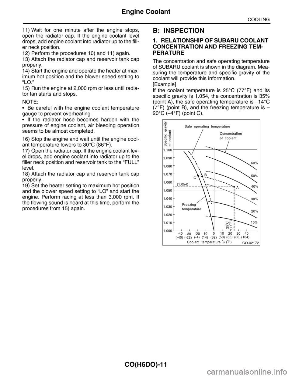
The concentration and safe operating temperature
of SUBARU coolant is shown in the diagram. Mea-
suring the temperature and specific gravity of the
coolant will provide this information.
[Example]
If the coolant temperature is 25°C (77°F) and its
specific gravity is 1.054, the concentration is 35%
(point A), the safe operating temperature is –14°C
(7°F) (point B), and the freezing temperature is –
20°C (–4°F) (point C).
CO-02172
60%
(1.054)
1.000
1.010
1.020
1.030
1.040
1.050
1.060
1.070
1.080
1.090
1.100
Safe operating temperature
Freezingtemperature
Concentrationof coolant
Specific gravityof coolant
Coolant temperature
B
A
C
-40(-40) (-22)(-4)(14)(32)(50) (68) (86)
( F)
(104)-30-20 -10010203040
(77 F)
50%
40%
30%
20%
25 C
10%
C
Page 1166 of 2453
EN(H6DO)(diag)-5
General Description
ENGINE (DIAGNOSTICS)
3. General Description
A: CAUTION
1) Airbag system wiring harness is routed near the
ECM, main relay and fuel pump relay.
CAUTION:
•All airbag system wiring harnesses and con-
nectors are colored yellow. Do not use electri-
cal test equipment on these circuits.
•Be careful not to damage the airbag system
wiring harness when servicing the ECM, TCM,
main relay and fuel pump relay.
2) Never connect the battery in reverse polarity.
•The ECM will be destroyed instantly.
•The fuel injector and other parts will be dam-
aged.
3) Do not disconnect the battery terminals while the
engine is running.
A large counter electromotive force will be generat-
ed in the generator, and this voltage may damage
electronic parts such as ECM etc.
4) Before disconnecting the connectors of each
sensor and ECM, be sure to turn the ignition switch
to OFF. Perform the clear memory mode after con-
necting the connectors.
5) Poor contact has been identified as a primary
cause of this problem. Measure the voltage or re-
sistance of individual sensor or all electrical control
modules using a tapered pin with a diameter of less
than 0.64 mm (0.025 in). Do not insert the pin more
than 5 mm (0.20 in) into the part.
6) Remove the ECM from the located position after
disconnecting two cables on battery.
Otherwise, the ECM may be damaged.
CAUTION:
When replacing the ECM, be careful not to use
the wrong spec. ECM to avoid any damage on
the fuel injection system.
7) Connectors of each sensor in the engine com-
partment and the harness connectors on the en-
gine side and body side are all designed to be
waterproof. Even if the connectors are waterproof,
take care not to allow water to get into them when
washing the vehicle, or when servicing the vehicle
in rainy weather.
8) Use ECM mounting stud bolts as the grounding
point to chassis when measuring voltage and resis-
tance in the passenger compartment.
9) Use the engine ground terminal or engine as-
sembly as the grounding point to chassis when
measuring the voltage and resistance in engine
compartment.
10) Every MFI-related part is a precision part. Do
not drop them.
11) Observe the following cautions when installing
a radio in MFI equipped models.
CAUTION:
•The antenna must be kept as far apart as pos-
sible from control unit. (The ECM is located un-
der the steering column, inside of the
instrument panel lower trim panel.)
•The antenna feeder must be placed as far apart
as possible from the ECM and MFI harness.
•Carefully adjust the antenna for correct
matching.
•When mounting a large power type radio, pay
special attention to the three items mentioned
above.
•Incorrect installation of the radio may affect
the operation of ECM.
12) Release the pressure in the fuel system before
disconnecting the fuel hose. If engine starts during
this operation, run it until it stops.
13) For the model with ABS, the ABS warning light
may illuminate when performing driving test with
jacked-up or lifted-up condition, but this is not a
system malfunction. The reason for this is the
speed difference between the front and rear
wheels. After diagnosis of engine control system,
perform the ABS memory clear procedure of self-
diagnosis function.
B: INSPECTION
Before performing diagnostics, check the following
item which might affect engine problems.
1. BATTERY
1) Measure the battery voltage and specific gravity
of electrolyte.
Standard voltage: 12 V
Specific gravity: Above 1.260
2) Check the condition of the main and other fuses,
and harnesses and connectors. Also check for
proper grounding.
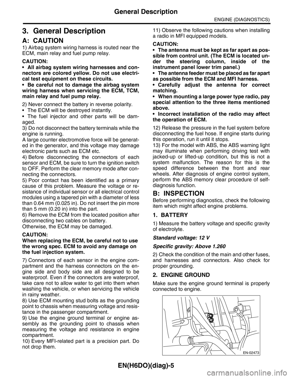
2. ENGINE GROUND
Make sure the engine ground terminal is properly
connected to engine.
EN-02473
Page 1193 of 2453
![SUBARU TRIBECA 2009 1.G Service Owners Manual EN(H6DO)(diag)-32
Subaru Select Monitor
ENGINE (DIAGNOSTICS)
7. LED OPERATION MODE FOR ENGINE
1) On the «Main Menu» display screen, select the {Each System Check} and press the [YES] key.
2) On the SUBARU TRIBECA 2009 1.G Service Owners Manual EN(H6DO)(diag)-32
Subaru Select Monitor
ENGINE (DIAGNOSTICS)
7. LED OPERATION MODE FOR ENGINE
1) On the «Main Menu» display screen, select the {Each System Check} and press the [YES] key.
2) On the](/img/17/7322/w960_7322-1192.png)
EN(H6DO)(diag)-32
Subaru Select Monitor
ENGINE (DIAGNOSTICS)
7. LED OPERATION MODE FOR ENGINE
1) On the «Main Menu» display screen, select the {Each System Check} and press the [YES] key.
2) On the «System Selection Menu» display screen, select the {Engine} and press the [YES] key.
3) Press the [YES] key after the information of engine type has been displayed.
4) On the «Engine Diagnosis» display screen, select the {Current Data Display/Save}, and then press the
[YES] key.
5) On the «Data Display» screen, select the {Data LED Display} and press the [YES] key.
6) Using the scroll key, scroll the display screen up or down until the desired data is shown.
•A list of the support data is shown in the following table.
NOTE:
For detailed operation procedure, refer to the “SUBARU SELECT MONITOR OPERATION MANUAL”.
Description Display Message When LED “ON” required
Te s t m o d e s i g n a l Te s t m o d e t e r m i n a l D c h e c k / U c h e c k D c h e c k
Neutral position switch signal Neutral SW Neutral/Other than neutral Neutral
Idle switch signal Soft idle SW Idle/Other than idle In idle
Ignition switch signal Ignition SW ON Input/OFF Input ON input
Pow er s te e r in g sw it c h s ig n al Pow er s te e r in g S W ON I np u t/ O FF I np u t ON i np ut
Air conditioning switch signal A/C SW ON Input/OFF Input ON input
Starter switch signal Starter SW ON Input/OFF Input ON input
Fr o nt ox yg e n mo n it o r 1 Ft O 2 mo n it o r 1 Le a n/ Ri ch Ric h
Fr o nt ox yg e n mo n it o r 2 Ft O 2 mo n it o r 2 Le a n/ Ri ch Ric h
Knocking signal Knock signal Yes/No Yes
Crankshaft position sensor signal Crankshaft angle signal Yes/No Yes
Camshaft position sensor signal Camshaft angle signal Yes/No Yes
Rear defogger switch signal Rear defogger SW ON Input/OFF Input ON input
Blower fan switch signal Blower fan SW ON Input/OFF Input ON input
Light switch signal Light SW ON Input/OFF Input ON input
Wiper switch signal Wiper SW ON Input/OFF Input ON input
A/C middle pressure switch signal A/C middle pressure SW ON Input/OFF Input ON input
Air conditioner compressor relay sig-
nalCompressor relay ON output/OFF output ON output
Drain valve signal Vent. Solenoid Valve ON or OFF When drain valve is ON.
AT r e t a r d a n g l e d e m a n d s i g n a l AT r e t a r d a n g l e d e m a n d Ye s / N o Ye s
AT f u e l c u t s i g n a l AT f u e l c u t Ye s / N o Ye s
VDC torque down prohibition output Torque down output ON/OFF Prohibition
VDC torque down demand Torque down demand Yes/No Yes
AT c o o r d i n a t e p e r m i s s i o n s i g n a lAT c o o r d i n a t e p e r m i s s i o n
signalON/OFF Permission
Electronic throttle control motor relay
signalETC motor relay ON/OFF ON
Stop light switch signal Stop SW ON Input/OFF Input ON input
SET/COAST switch signal SET/CST SW ON Input/OFF Input ON input
RESUME/ACCEL switch signal RES/ACC SW ON Input/OFF Input ON input
Brake switch signal Brake SW ON Input/OFF Input ON input
Main switch signal Main SW ON Input/OFF Input ON input
Body integrated unit data reception Body Int. Unit Data Yes/No Yes
Body integrated unit counter update Body Int. Unit Count Yes/No Yes
Cruise control cancel switch signal CC Cancel SW ON Input/OFF Input ON input
Va r i a b l e va l v e l i f t d i a g n o s i s o i l p r e s -
sure switch signal 1Oil Temperature SW1 ON/OFF ON
Va r i a b l e va l v e l i f t d i a g n o s i s o i l p r e s -
sure switch signal 2Oil Temperature SW2 ON/OFF ON
Page 1197 of 2453
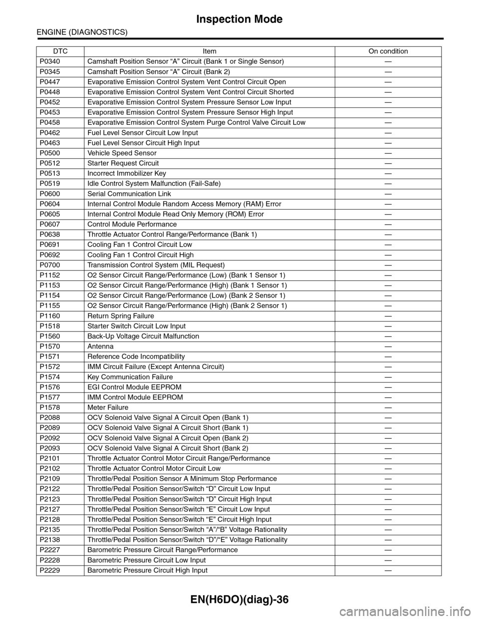
EN(H6DO)(diag)-36
Inspection Mode
ENGINE (DIAGNOSTICS)
P0340 Camshaft Position Sensor “A” Circuit (Bank 1 or Single Sensor) —
P0345 Camshaft Position Sensor “A” Circuit (Bank 2) —
P0447 Evaporative Emission Control System Vent Control Circuit Open —
P0448 Evaporative Emission Control System Vent Control Circuit Shorted —
P0452 Evaporative Emission Control System Pressure Sensor Low Input —
P0453 Evaporative Emission Control System Pressure Sensor High Input —
P0458 Evaporative Emission Control System Purge Control Valve Circuit Low —
P0462 Fuel Level Sensor Circuit Low Input —
P0463 Fuel Level Sensor Circuit High Input —
P0500 Vehicle Speed Sensor—
P0512 Starter Request Circuit—
P0513 Incorrect Immobilizer Key —
P0519 Idle Control System Malfunction (Fail-Safe) —
P0600 Serial Communication Link —
P0604 Internal Control Module Random Access Memory (RAM) Error —
P0605 Internal Control Module Read Only Memory (ROM) Error —
P0607 Control Module Performance —
P0638 Throttle Actuator Control Range/Performance (Bank 1) —
P0691 Cooling Fan 1 Control Circuit Low —
P0692 Cooling Fan 1 Control Circuit High —
P0700 Transmission Control System (MIL Request) —
P1152 O2 Sensor Circuit Range/Performance (Low) (Bank 1 Sensor 1) —
P1153 O2 Sensor Circuit Range/Performance (High) (Bank 1 Sensor 1) —
P1154 O2 Sensor Circuit Range/Performance (Low) (Bank 2 Sensor 1) —
P1155 O2 Sensor Circuit Range/Performance (High) (Bank 2 Sensor 1) —
P1160 Return Spring Failure—
P1518 Starter Switch Circuit Low Input —
P1560 Back-Up Voltage Circuit Malfunction —
P1570 Antenna—
P1571 Reference Code Incompatibility —
P1572 IMM Circuit Failure (Except Antenna Circuit) —
P1574 Key Communication Failure —
P1576 EGI Control Module EEPROM —
P1577 IMM Control Module EEPROM —
P1578 Meter Failure—
P2088 OCV Solenoid Valve Signal A Circuit Open (Bank 1) —
P2089 OCV Solenoid Valve Signal A Circuit Short (Bank 1) —
P2092 OCV Solenoid Valve Signal A Circuit Open (Bank 2) —
P2093 OCV Solenoid Valve Signal A Circuit Short (Bank 2) —
P2101 Throttle Actuator Control Motor Circuit Range/Performance —
P2102 Throttle Actuator Control Motor Circuit Low —
P2109 Throttle/Pedal Position Sensor A Minimum Stop Performance —
P2122 Throttle/Pedal Position Sensor/Switch “D” Circuit Low Input —
P2123 Throttle/Pedal Position Sensor/Switch “D” Circuit High Input —
P2127 Throttle/Pedal Position Sensor/Switch “E” Circuit Low Input —
P2128 Throttle/Pedal Position Sensor/Switch “E” Circuit High Input —
P2135 Throttle/Pedal Position Sensor/Switch “A”/“B” Voltage Rationality —
P2138 Throttle/Pedal Position Sensor/Switch “D”/“E” Voltage Rationality —
P2227 Barometric Pressure Circuit Range/Performance —
P2228 Barometric Pressure Circuit Low Input —
P2229 Barometric Pressure Circuit High Input —
DTC Item On condition
Page 1201 of 2453
EN(H6DO)(diag)-40
Drive Cycle
ENGINE (DIAGNOSTICS)
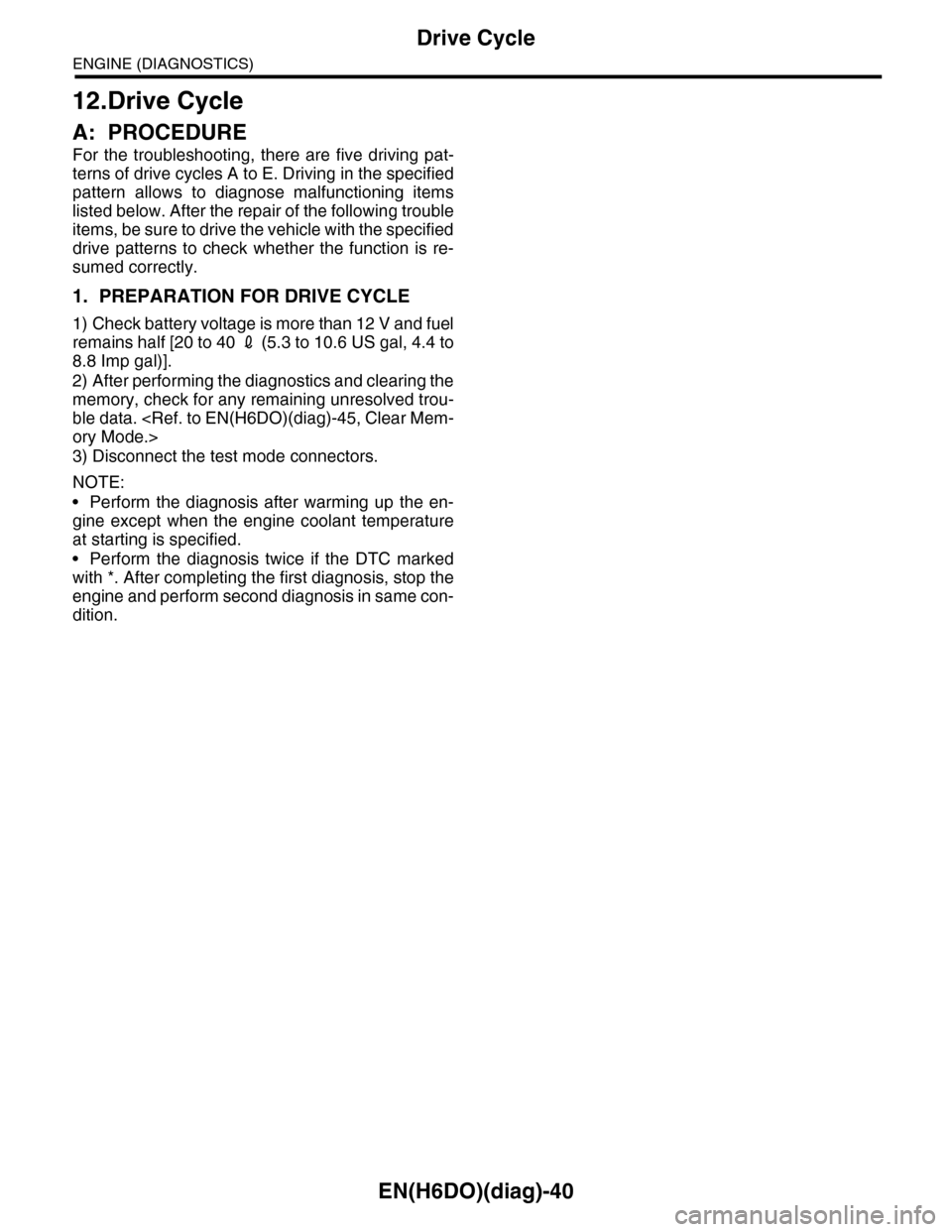
12.Drive Cycle
A: PROCEDURE
For the troubleshooting, there are five driving pat-
terns of drive cycles A to E. Driving in the specified
pattern allows to diagnose malfunctioning items
listed below. After the repair of the following trouble
items, be sure to drive the vehicle with the specified
drive patterns to check whether the function is re-
sumed correctly.
1. PREPARATION FOR DRIVE CYCLE
1) Check battery voltage is more than 12 V and fuel
remains half [20 to 40 2 (5.3 to 10.6 US gal, 4.4 to
8.8 Imp gal)].
2) After performing the diagnostics and clearing the
memory, check for any remaining unresolved trou-
ble data.
3) Disconnect the test mode connectors.
NOTE:
•Perform the diagnosis after warming up the en-
gine except when the engine coolant temperature
at starting is specified.
•Perform the diagnosis twice if the DTC marked
with *. After completing the first diagnosis, stop the
engine and perform second diagnosis in same con-
dition.
Page 1669 of 2453
GD(H6DO)-57
Diagnostic Trouble Code (DTC) Detecting Criteria
GENERAL DESCRIPTION
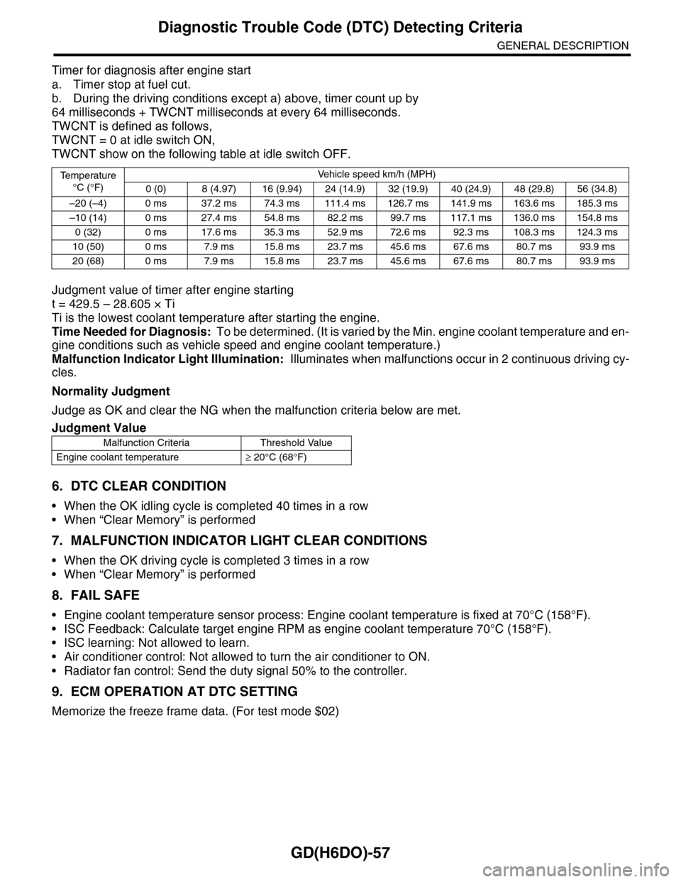
Timer for diagnosis after engine start
a. Timer stop at fuel cut.
b. During the driving conditions except a) above, timer count up by
64 milliseconds + TWCNT milliseconds at every 64 milliseconds.
TWCNT is defined as follows,
TWCNT = 0 at idle switch ON,
TWCNT show on the following table at idle switch OFF.
Judgment value of timer after engine starting
t = 429.5 – 28.605 × Ti
Ti is the lowest coolant temperature after starting the engine.
Time Needed for Diagnosis: To be determined. (It is varied by the Min. engine coolant temperature and en-
gine conditions such as vehicle speed and engine coolant temperature.)
Malfunction Indicator Light Illumination: Illuminates when malfunctions occur in 2 continuous driving cy-
cles.
Normality Judgment
Judge as OK and clear the NG when the malfunction criteria below are met.
6. DTC CLEAR CONDITION
•When the OK idling cycle is completed 40 times in a row
•When “Clear Memory” is performed
7. MALFUNCTION INDICATOR LIGHT CLEAR CONDITIONS
•When the OK driving cycle is completed 3 times in a row
•When “Clear Memory” is performed
8. FAIL SAFE
•Engine coolant temperature sensor process: Engine coolant temperature is fixed at 70°C (158°F).
•ISC Feedback: Calculate target engine RPM as engine coolant temperature 70°C (158°F).
•ISC learning: Not allowed to learn.
•Air conditioner control: Not allowed to turn the air conditioner to ON.
•Radiator fan control: Send the duty signal 50% to the controller.
9. ECM OPERATION AT DTC SETTING
Memorize the freeze frame data. (For test mode $02)
Te m p e r a t u r e
°C (°F)
Ve h i c l e s p e e d k m / h ( M P H )
0 (0) 8 (4.97) 16 (9.94) 24 (14.9) 32 (19.9) 40 (24.9) 48 (29.8) 56 (34.8)
–20 (–4) 0 ms 37.2 ms 74.3 ms 111.4 ms 126.7 ms 141.9 ms 163.6 ms 185.3 ms
–10 (14) 0 ms 27.4 ms 54.8 ms 82.2 ms 99.7 ms 117.1 ms 136.0 ms 154.8 ms
0 (32) 0 ms 17.6 ms 35.3 ms 52.9 ms 72.6 ms 92.3 ms 108.3 ms 124.3 ms
10 (50) 0 ms 7.9 ms 15.8 ms 23.7 ms 45.6 ms 67.6 ms 80.7 ms 93.9 ms
20 (68) 0 ms 7.9 ms 15.8 ms 23.7 ms 45.6 ms 67.6 ms 80.7 ms 93.9 ms
Judgment Value
Malfunction Criteria Threshold Value
Engine coolant temperature≥ 20°C (68°F)
Page 1670 of 2453
GD(H6DO)-58
Diagnostic Trouble Code (DTC) Detecting Criteria
GENERAL DESCRIPTION
AI: DTC P0126 INSUFFICIENT COOLANT TEMPERATURE FOR STABLE OPER-
ATION
1. OUTLINE OF DIAGNOSIS
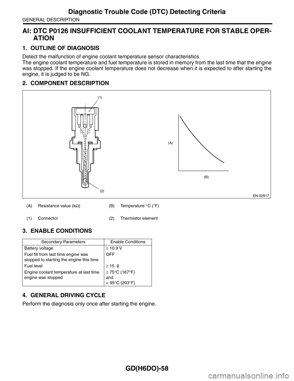
Detect the malfunction of engine coolant temperature sensor characteristics.
The engine coolant temperature and fuel temperature is stored in memory from the last time that the engine
was stopped. If the engine coolant temperature does not decrease when it is expected to after starting the
engine, it is judged to be NG.
2. COMPONENT DESCRIPTION
3. ENABLE CONDITIONS
4. GENERAL DRIVING CYCLE
Perform the diagnosis only once after starting the engine.
(A) Resistance value (kΩ)(B)Temperature °C (°F)
(1) Connector (2) Thermistor element
Secondary Parameters Enable Conditions
Battery voltage≥ 10.9 V
Fuel fill from last time engine was
stopped to starting the engine this time
OFF
Fuel level≥ 15 2
Engine coolant temperature at last time
engine was stopped
≥ 75°C (167°F)
and
< 95°C (203°F)
EN-02917
(A)
(2)
(1)
(B)
Page 1671 of 2453
GD(H6DO)-59
Diagnostic Trouble Code (DTC) Detecting Criteria
GENERAL DESCRIPTION
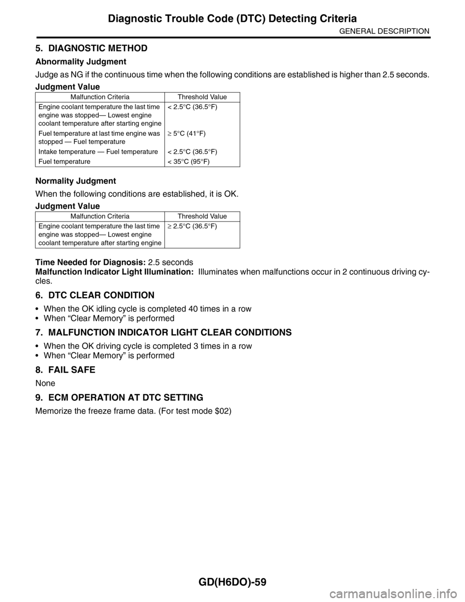
5. DIAGNOSTIC METHOD
Abnormality Judgment
Judge as NG if the continuous time when the following conditions are established is higher than 2.5 seconds.
Normality Judgment
When the following conditions are established, it is OK.
Time Needed for Diagnosis: 2.5 seconds
Malfunction Indicator Light Illumination: Illuminates when malfunctions occur in 2 continuous driving cy-
cles.
6. DTC CLEAR CONDITION
•When the OK idling cycle is completed 40 times in a row
•When “Clear Memory” is performed
7. MALFUNCTION INDICATOR LIGHT CLEAR CONDITIONS
•When the OK driving cycle is completed 3 times in a row
•When “Clear Memory” is performed
8. FAIL SAFE
None
9. ECM OPERATION AT DTC SETTING
Memorize the freeze frame data. (For test mode $02)
Judgment Value
Malfunction Criteria Threshold Value
Engine coolant temperature the last time
engine was stopped— Lowest engine
coolant temperature after starting engine
< 2.5°C (36.5°F)
Fuel temperature at last time engine was
stopped — Fuel temperature
≥ 5°C (41°F)
Intake temperature — Fuel temperature < 2.5°C (36.5°F)
Fuel temperature < 35°C (95°F)
Judgment Value
Malfunction Criteria Threshold Value
Engine coolant temperature the last time
engine was stopped— Lowest engine
coolant temperature after starting engine
≥ 2.5°C (36.5°F)