key SUBARU TRIBECA 2009 1.G Service Manual Online
[x] Cancel search | Manufacturer: SUBARU, Model Year: 2009, Model line: TRIBECA, Model: SUBARU TRIBECA 2009 1.GPages: 2453, PDF Size: 46.32 MB
Page 676 of 2453
SL-47
Key Lock Cylinders
SECURITY AND LOCKS
18.Key Lock Cylinders
A: REPLACEMENT
1) Raise the front door glass to the top position.
2) Remove the door trim.
3) Remove the sealing cover.
4) Remove the plug at the rear end of the panel.
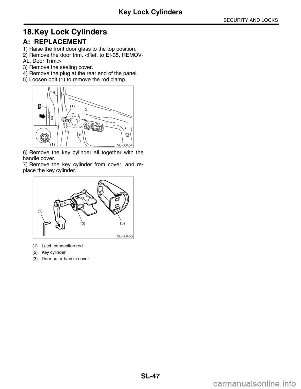
5) Loosen bolt (1) to remove the rod clamp.
6) Remove the key cylinder all together with the
handle cover.
7) Remove the key cylinder from cover, and re-
place the key cylinder.
(1) Latch connection rod
(2) Key cylinder
(3) Door outer handle cover
SL-00454
(1)
(1)
SL-00455
(1)
(2)(3)
Page 678 of 2453
SL-49
Impact Sensor
SECURITY AND LOCKS
20.Impact Sensor
A: REMOVAL
1) Remove the key from ignition switch.
2) Close all doors and the rear gate.
3) Press the UNLOCK button of the keyless trans-
mitter.
4) Change the setting of impact sensor using Sub-
aru Select Monitor.
5) Disconnect the ground cable from battery.
6) Remove the impact sensor.
B: INSTALLATION
1) Remove the key from ignition switch.
2) Close all doors and the rear gate.
3) Press the UNLOCK button of the keyless trans-
mitter.
4) Disconnect the ground cable from battery.
5) Install the impact sensor.
6) Connect the ground cable to the battery.
7) Change the setting of impact sensor using Sub-
aru Select Monitor.
C: OPERATION
1. IMPACT SENSOR SETTING USING SUB-
ARU SELECT MONITOR
1) Connect the Subaru Select Monitor to data link
connector.
2) Turn the ignition switch to ON.
3) Select {Integ. unit} from main menu.
4) Select {ECU customizing}.
5) Make a impact monitor setting.
•When installing: ON
•When removing: OFF
6) Make a impact monitor ON/OFF setting.
•When installing: ON
•When removing: OFF
7) Turn the ignition switch to OFF, and then remove
the Subaru Select Monitor.
D: ADJUSTMENT
1. CHECK IMPACT SENSOR
1) Remove the key from ignition switch.
2) Close all windows.
3) Close all doors and the rear gate. Leave open
the front hood.
4) Press the LOCK button of the keyless transmit-
ter from outside of vehicle.
5) Check that the security indicator light blinks
twice within 0.5 seconds in 2 seconds cycle after 30
seconds.
6) Hit the windshield with your palm continuously
and check the security alarm operates. Lift up the
front hood approx. 12 cm (4.7 in) or more, and then
drop it off to check the operation of security alarm.
7) If NG, adjust the impact sensitivity.
2. IMPACT SENSITIVITY ADJUSTMENT
1) Connect the Subaru Select Monitor to data link
connector.
2) Turn the ignition switch to ON.
3) Select {Impact Sensor} from the main menu.
4) Make a {ECU customizing}.
•Sensitivity can be adjusted in 11 levels (0 to 10).
•Initial setting is 5.
•Smaller number means more sensitive.
•Larger number means less sensitive.
5) Turn the ignition switch to OFF, and then remove
the Subaru Select Monitor.
NOTE:
•Set the sensor so as not to let the alarm on nor-
mal vibration (reclining to the door, hit the ball and
etc.).
•Set the sensor to operate the alarm with hitting
the door or window glass, etc. continuously like a
mayhem by robbery.
•Ask the customer about parking situation for set-
ting, because the alarm operate when the vibration
not only the burglar but also the construction etc.
Page 679 of 2453
SL-50
Keyless Entry Control Module
SECURITY AND LOCKS
21.Keyless Entry Control Module
A: REMOVAL
1) Disconnect the ground cable from battery.
2) Remove the glove box.
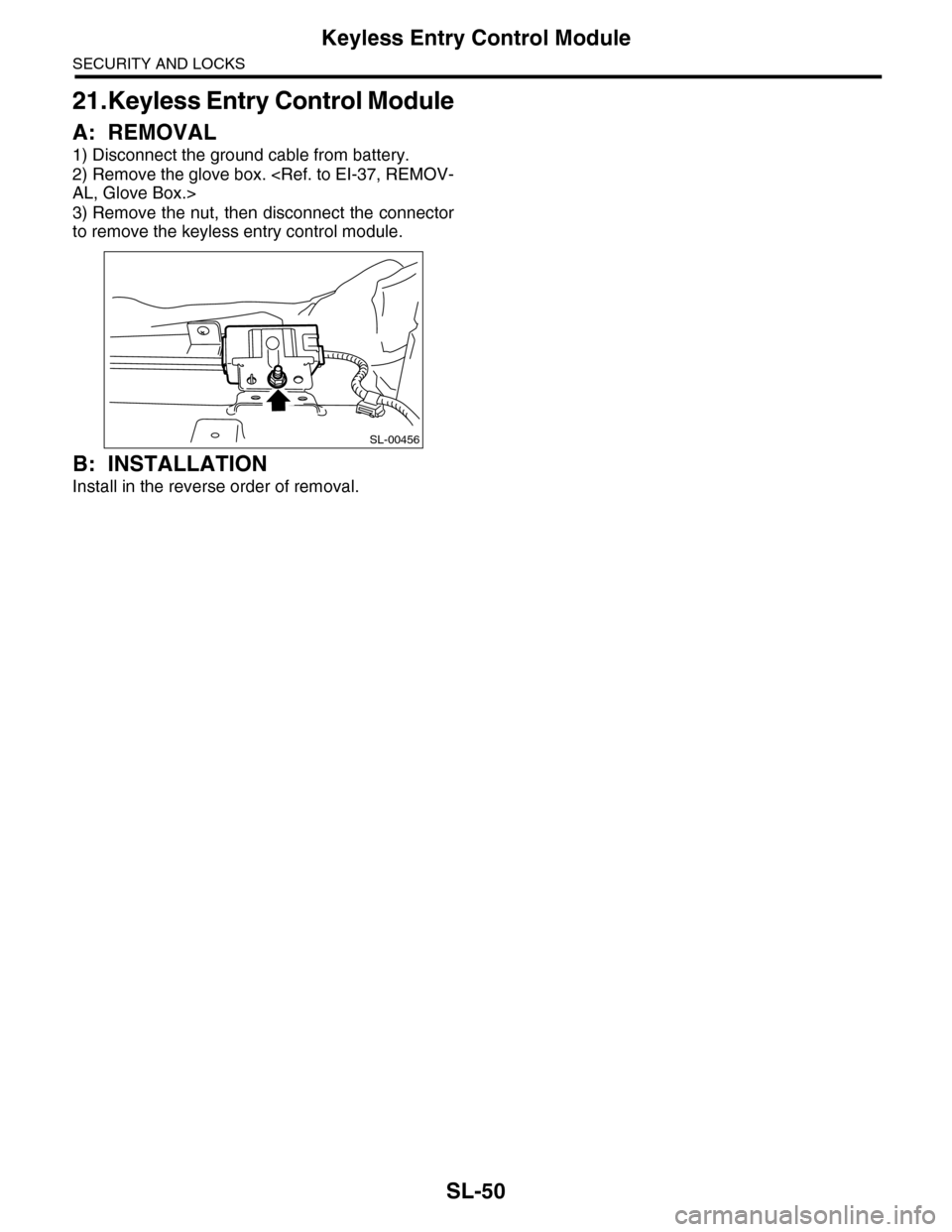
3) Remove the nut, then disconnect the connector
to remove the keyless entry control module.
B: INSTALLATION
Install in the reverse order of removal.
SL-00456
Page 680 of 2453
SL-51
Keyless Buzzer
SECURITY AND LOCKS
22.Keyless Buzzer
A: REMOVAL
1) Disconnect the ground cable from battery.
2) Remove the keyless buzzer installed to the
backside of radiator bracket.
B: INSTALLATION
Install in the reverse order of removal.
C: INSPECTION
Install the keyless buzzer to another vehicle which
operates keyless buzzer normally, check the buzz-
er sounds. If NG, replace the keyless buzzer.
Page 681 of 2453
SL-52
Body Integrated Unit
SECURITY AND LOCKS
23.Body Integrated Unit
A: REMOVAL
NOTE:
•When replacing the body integrated unit, check
the current setting and note it.
OPERATION, Subaru Select Monitor.>
•When replacing the body integrated unit, all im-
mobilizer keys also must be replaced and regis-
tered again.
1) Disconnect the ground cable from battery.
2) Remove the instrument panel lower cover.
er.>
3) Disconnect the connector of body integrated
unit.
CAUTION:
•Be careful to keep water and other foreign
materials away from body integrated unit.
•Do not attach or register the immobilizer re-
lated unit which is already registered to another
vehicle, for the purpose of diagnosis or func-
tion check.
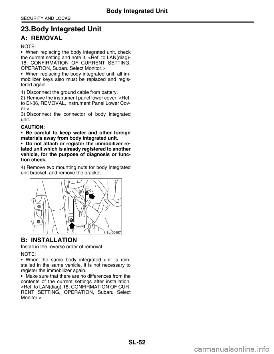
4) Remove two mounting nuts for body integrated
unit bracket, and remove the bracket.
B: INSTALLATION
Install in the reverse order of removal.
NOTE:
•When the same body integrated unit is rein-
stalled in the same vehicle, it is not necessary to
register the immobilizer again.
•Make sure that there are no differences from the
contents of the current settings after installation.
Monitor.>
SL-00457
Page 682 of 2453
SL-53
Transmitter
SECURITY AND LOCKS
24.Transmitter
A: REMOVAL
1. TRANSMITTER BATTERY
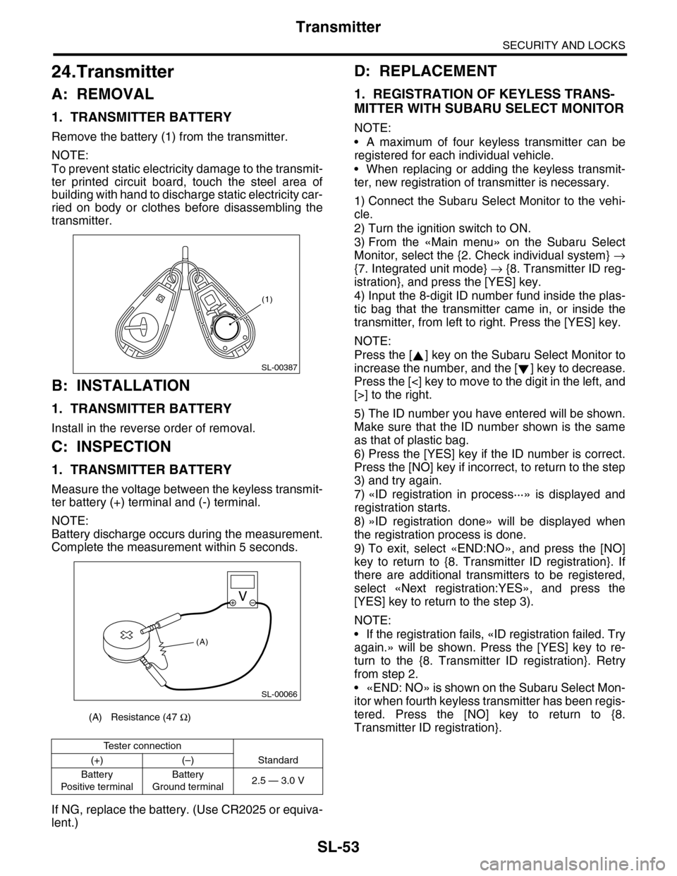
Remove the battery (1) from the transmitter.
NOTE:
To prevent static electricity damage to the transmit-
ter printed circuit board, touch the steel area of
building with hand to discharge static electricity car-
ried on body or clothes before disassembling the
transmitter.
B: INSTALLATION
1. TRANSMITTER BATTERY
Install in the reverse order of removal.
C: INSPECTION
1. TRANSMITTER BATTERY
Measure the voltage between the keyless transmit-
ter battery (+) terminal and (-) terminal.
NOTE:
Battery discharge occurs during the measurement.
Complete the measurement within 5 seconds.
If NG, replace the battery. (Use CR2025 or equiva-
lent.)
D: REPLACEMENT
1. REGISTRATION OF KEYLESS TRANS-
MITTER WITH SUBARU SELECT MONITOR
NOTE:
•A maximum of four keyless transmitter can be
registered for each individual vehicle.
•When replacing or adding the keyless transmit-
ter, new registration of transmitter is necessary.
1) Connect the Subaru Select Monitor to the vehi-
cle.
2) Turn the ignition switch to ON.
3) From the «Main menu» on the Subaru Select
Monitor, select the {2. Check individual system} →
{7. Integrated unit mode} → {8. Transmitter ID reg-
istration}, and press the [YES] key.
4) Input the 8-digit ID number fund inside the plas-
tic bag that the transmitter came in, or inside the
transmitter, from left to right. Press the [YES] key.
NOTE:
Press the [ ] key on the Subaru Select Monitor to
increase the number, and the [ ] key to decrease.
Press the [<] key to move to the digit in the left, and
[>] to the right.
5) The ID number you have entered will be shown.
Make sure that the ID number shown is the same
as that of plastic bag.
6) Press the [YES] key if the ID number is correct.
Press the [NO] key if incorrect, to return to the step
3) and try again.
7) «ID registration in process···» is displayed and
registration starts.
8) »ID registration done» will be displayed when
the registration process is done.
9) To exit, select «END:NO», and press the [NO]
key to return to {8. Transmitter ID registration}. If
there are additional transmitters to be registered,
select «Next registration:YES», and press the
[YES] key to return to the step 3).
NOTE:
•If the registration fails, «ID registration failed. Try
again.» will be shown. Press the [YES] key to re-
turn to the {8. Transmitter ID registration}. Retry
from step 2.
•«END: NO» is shown on the Subaru Select Mon-
itor when fourth keyless transmitter has been regis-
tered. Press the [NO] key to return to {8.
Transmitter ID registration}.(A) Resistance (47 Ω)
Te s t e r c o n n e c t i o n
(+) (–) Standard
Battery
Po si t ive t e r mi na l
Battery
Ground terminal2.5 — 3.0 V
(1)
SL-00387
SL-00066
(A)
Page 758 of 2453
BVC(diag)-3
Check List for Interview
BRAKE VACUUM CONTROL (BVC) (DIAGNOSTICS)
2. Check List for Interview
A: CHECK
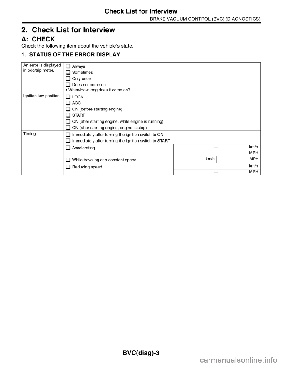
Check the following item about the vehicle’s state.
1. STATUS OF THE ERROR DISPLAY
An error is displayed
in odo/trip meter. Always
Sometimes
Only once
Does not come on
• When/How long does it come on?
Ignition key position LOCK
ACC
ON (before starting engine)
START
ON (after starting engine, while engine is running)
ON (after starting engine, engine is stop)
Timing Immediately after turning the ignition switch to ON
Immediately after turning the ignition switch to START
Accelerating — km/h
— MPH
While traveling at a constant speedkm/h MPH
Reducing speed — km/h
— MPH
Page 764 of 2453
BVC(diag)-9
Subaru Select Monitor
BRAKE VACUUM CONTROL (BVC) (DIAGNOSTICS)
6. Subaru Select Monitor
A: OPERATION
1. READ DIAGNOSTIC TROUBLE CODE
(DTC)
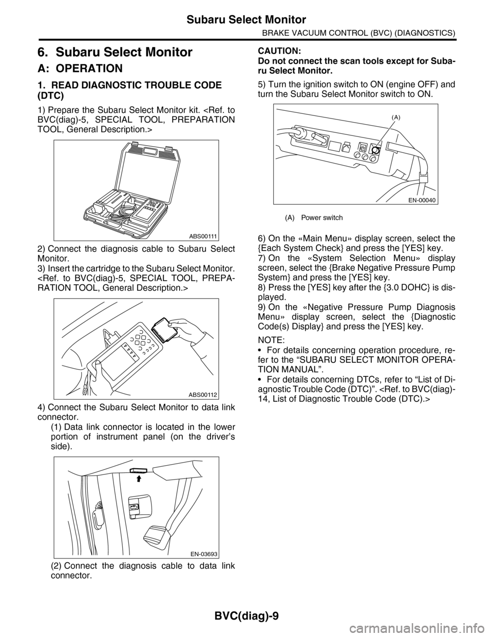
1) Prepare the Subaru Select Monitor kit.
TOOL, General Description.>
2) Connect the diagnosis cable to Subaru Select
Monitor.
3) Insert the cartridge to the Subaru Select Monitor.
4) Connect the Subaru Select Monitor to data link
connector.
(1) Data link connector is located in the lower
portion of instrument panel (on the driver’s
side).
(2) Connect the diagnosis cable to data link
connector.
CAUTION:
Do not connect the scan tools except for Suba-
ru Select Monitor.
5) Turn the ignition switch to ON (engine OFF) and
turn the Subaru Select Monitor switch to ON.
6) On the «Main Menu» display screen, select the
{Each System Check} and press the [YES] key.
7) On the «System Selection Menu» display
screen, select the {Brake Negative Pressure Pump
System} and press the [YES] key.
8) Press the [YES] key after the {3.0 DOHC} is dis-
played.
9) On the «Negative Pressure Pump Diagnosis
Menu» display screen, select the {Diagnostic
Code(s) Display} and press the [YES] key.
NOTE:
•For details concerning operation procedure, re-
fer to the “SUBARU SELECT MONITOR OPERA-
TION MANUAL”.
•For details concerning DTCs, refer to “List of Di-
agnostic Trouble Code (DTC)”.
ABS00111
ABS00112
EN-03693
(A) Power switch
(A)
EN-00040
Page 765 of 2453
![SUBARU TRIBECA 2009 1.G Service Manual Online BVC(diag)-10
Subaru Select Monitor
BRAKE VACUUM CONTROL (BVC) (DIAGNOSTICS)
2. READ CURRENT DATA
1) On the «Main Menu» display screen, select the {Each System Check} and press the [YES] key.
2) On t SUBARU TRIBECA 2009 1.G Service Manual Online BVC(diag)-10
Subaru Select Monitor
BRAKE VACUUM CONTROL (BVC) (DIAGNOSTICS)
2. READ CURRENT DATA
1) On the «Main Menu» display screen, select the {Each System Check} and press the [YES] key.
2) On t](/img/17/7322/w960_7322-764.png)
BVC(diag)-10
Subaru Select Monitor
BRAKE VACUUM CONTROL (BVC) (DIAGNOSTICS)
2. READ CURRENT DATA
1) On the «Main Menu» display screen, select the {Each System Check} and press the [YES] key.
2) On the «System Selection Menu» display screen, select the {Brake Negative Pressure Pump System} and
press the [YES] key.
3) Press the [YES] key after the {3.0 DOHC} is displayed.
4) On the «Negative Pressure Diagnosis Menu» display screen, select the {Current Data Display/Save}, and
then press the [YES] key.
5) On the «Data Display Menu» screen, select the {Data Display} and press the [YES] key.
6) Using a scroll key, scroll the display screen up or down until necessary data is shown.
•A list of the support data is shown in the following table.
NOTE:
For details concerning operation procedure, refer to the “SUBARU SELECT MONITOR OPERATION MAN-
UAL”.
3. CLEAR MEMORY MODE
1) On the «Main Menu» display screen, select the
{Each System Check} and press the [YES] key.
2) On the «System Selection Menu» display
screen, select the {Brake Negative Pressure Pump
System} and press the [YES] key.
3) Press the [YES] key after the {3.0 DOHC} is dis-
played.
4) On the «Negative Pressure Pump Diagnosis
Menu» display screen, select the {Clear Memory}
and press the [YES] key.
5) When “Done” and “Turn ignition switch OFF” are
shown on the display screen, turn the Subaru Se-
lect Monitor and ignition switch to OFF.
NOTE:
For details concerning operation procedure, refer
to the “SUBARU SELECT MONITOR OPERATION
MANUAL”.
4. FUNCTION CHECK MODE
1) Connect the test mode connector located under
the glove box.
2) Turn the ignition switch to ON (engine OFF) and
turn the Subaru Select Monitor switch to ON.
3) On the «Main Menu» display screen, select the
{Each System Check} and press the [YES] key.
4) On the «System Selection Menu» display
screen, select the {Brake Negative Pressure Pump
System} and press the [YES] key.
5) Press the [YES] key after the {3.0 DOHC} is dis-
played.
6) On the «Negative Pressure Pump Diagnosis
Menu» display screen, select the {Function Check
Mode} and press the [YES] key.
7) When the “Start Function Check Mode” is shown
on the screen, press the [YES] key.
8) When the “Depress the Brake Pedal 5 Times” is
shown on the screen, depress the brake pedal 5
times, and press the [YES] key while brake pedal is
not depressed.
9) Press the [YES] key after the {OK} is displayed.
Display Contents to be monitored Unit of measure
Atmospheric pressure Atmospheric pressure is displayed. mmHg, kPa or psig
Brake booster pressure Brake booster pressure is displayed. mmHg, kPa or psig
Te s t m o d e t e r m i n a l Te s t m o d e t e r m i n a l c o n n e c t i o n s t a t u s i s d i s p l a y e d . D C h e c k o r U C h e c k
Negative pressure pump motor Negative pressure motor operating status is displayed. ON or OFF
Negative pressure pump motor relay Negative pressure pump motor relay operating status is displayed. ON or OFF
Display Contents to be monitored
Clear Memory? DTC deleting function
(A) Test mode connector
EN-03694
(4)
Page 896 of 2453
PS-16
Tilt Steering Column
POWER ASSISTED SYSTEM (POWER STEERING)
B: INSTALLATION
1) Insert the end of the steering shaft into the toe
board.
2) With the tilt lever secured, tighten the steering
shaft mounting bolts under instrument panel.
Tightening torque:
25 N·m (2.5 kgf-m, 18.1 ft-lb)
3) Connect all the connectors under the instrument
panel.
4) Connect the airbag system connector at the har-
ness spool.
NOTE:
Make sure to apply double lock.
5) Install the instrument panel lower cover with tilt
lever held in the lowered position.
6) Install the universal joint.
7) Align the center position of the roll connector.
8) Install the steering wheel.
CAUTION:
Insert the roll connector guide pin into the
guide hole on lower end of steering wheel sur-
face to prevent damage.
C: DISASSEMBLY
Remove the two screws securing the upper steer-
ing column covers, and the two screws securing
the combination switch, and then remove related
parts.
D: ASSEMBLY
Insert the combination switch to the upper column
shaft, and install the upper column cover. Then
route the ignition key harness and combination
switch harness between the column cover mount-
ing bosses.
Tightening torque:
1.2 N·m (0.12 kgf-m, 0.9 ft-lb)
CAUTION:
Do not overtorque the screw.
E: INSPECTION
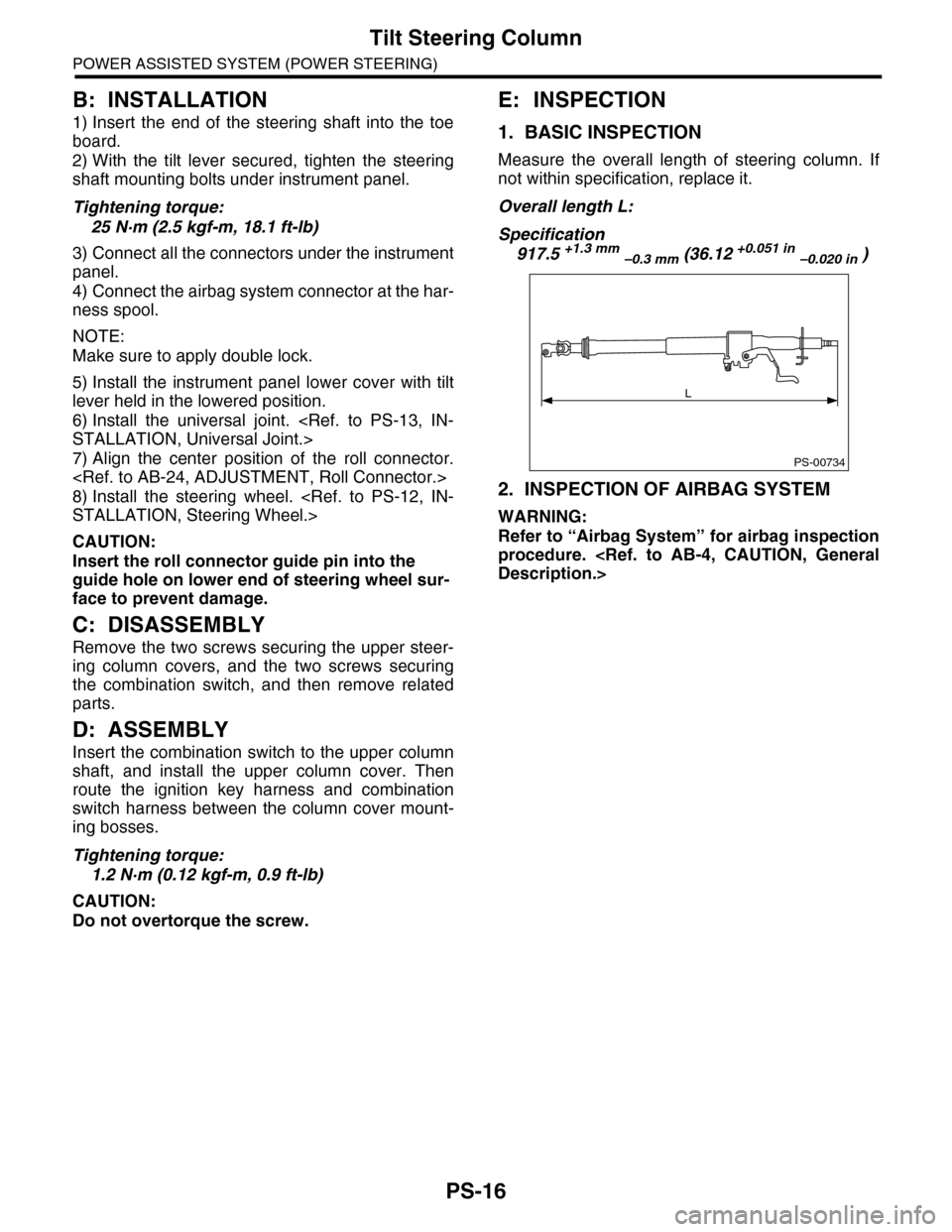
1. BASIC INSPECTION
Measure the overall length of steering column. If
not within specification, replace it.
Overall length L:
Specification
917.5 +1.3 mm –0.3 mm (36.12 +0.051 in –0.020 in )
2. INSPECTION OF AIRBAG SYSTEM
WARNING:
Refer to “Airbag System” for airbag inspection
procedure.
PS-00734
L