key SUBARU TRIBECA 2009 1.G Service Repair Manual
[x] Cancel search | Manufacturer: SUBARU, Model Year: 2009, Model line: TRIBECA, Model: SUBARU TRIBECA 2009 1.GPages: 2453, PDF Size: 46.32 MB
Page 568 of 2453
LI-35
Ignition Switch Illumination
LIGHTING SYSTEM
33.Ignition Switch Illumination
A: REMOVAL
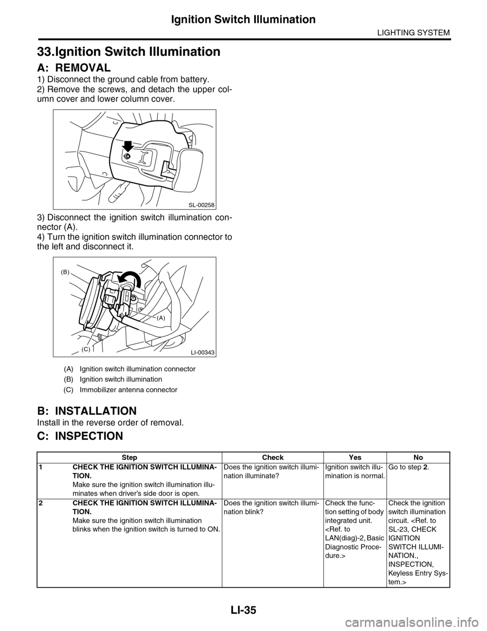
1) Disconnect the ground cable from battery.
2) Remove the screws, and detach the upper col-
umn cover and lower column cover.
3) Disconnect the ignition switch illumination con-
nector (A).
4) Turn the ignition switch illumination connector to
the left and disconnect it.
B: INSTALLATION
Install in the reverse order of removal.
C: INSPECTION
(A) Ignition switch illumination connector
(B) Ignition switch illumination
(C) Immobilizer antenna connector
SL-00258
LI-00343(C)
(B)
(A)
Step Check Yes No
1CHECK THE IGNITION SWITCH ILLUMINA-
TION.
Make sure the ignition switch illumination illu-
minates when driver’s side door is open.
Does the ignition switch illumi-
nation illuminate?
Ignition switch illu-
mination is normal.
Go to step 2.
2CHECK THE IGNITION SWITCH ILLUMINA-
TION.
Make sure the ignition switch illumination
blinks when the ignition switch is turned to ON.
Does the ignition switch illumi-
nation blink?
Check the func-
tion setting of body
integrated unit.
Diagnostic Proce-
dure.>
Check the ignition
switch illumination
circuit.
IGNITION
SWITCH ILLUMI-
NATION.,
INSPECTION,
Keyless Entr y Sys-
tem.>
Page 585 of 2453
OD(diag)-17
Subaru Select Monitor
OCCUPANT DETECTION SYSTEM (DIAGNOSTICS)
7. Subaru Select Monitor
A: OPERATION
1. READ DIAGNOSTIC TROUBLE CODE (DTC)
When malfunction of the airbag system and the occupant detection system occur, the DTC stored in airbag
control module will be read out.
Refer to the DTC readout of the airbag system (diagnosis).
NOTE:
•For details concerning operation procedure, refer to the “SUBARU SELECT MONITOR OPERATION
MANUAL”.
•For details concerning DTCs, refer to the “List of Diagnostic Trouble Code (Airbag system, Occupant de-
tection system).”
2. DISPLAY OF STATUS INFORMATION
Check the operating condition of each sensor in the event of malfunction in seat belt buckle switch and seat
position sensor, or when the seat belt buckle switch and seat position sensor has been replaced.
1) On the «Main Menu» display screen, select the {Each System Check} and press the [YES] key.
2) On the «System Selection Menu» display screen, select the {Airbag System} and press the [YES] key.
3) On the «Airbag System» display screen, select the {Status Data} and press the [YES] key.
The following table is for support data.
*1: The seat position is forward.
*2: The seat position is rearward.
*3: Displayed when data other than before and behind the seat, such as the breakdown etc, is input.
*4: Displayed when it is initial.
*5: Seat position sensor not supported
*6. Seat belt fastened
*7. Seat belt not fastened
*8: Displayed when data other than belt fastened or not fastened, such as breakdowns is input.
*9: Seat belt buckle switch not supported
*10: Passenger's seat air bag operating state
*11: Passenger's seat air bag non-operating state
NOTE:
For details concerning operation procedure, refer to the “SUBARU SELECT MONITOR OPERATION MAN-
UAL”.
Item Display Contents
Seat position sensor LHFr o nt p os it i on *1/Rear position *2 /Other *3/Initial Setting *3 /–– *5
Seat position sensor RH–– *5
Seat belt buckle switch LHBuckled *6/Unbuckled *7 /Other *8/Initial Setting *4 /–– *9
Seat belt buckle switch RHBuckled *6/Unbuckled *7 /Other *8/Initial Setting *4 /–– *9
Passenger’s airbag control statusON *10/OFF *11 /Initial Setting *4
Page 586 of 2453
OD(diag)-18
Subaru Select Monitor
OCCUPANT DETECTION SYSTEM (DIAGNOSTICS)
3. CLEAR MEMORY MODE
Clear the DTC stored in the airbag control module
after repairing the airbag system and occupant de-
tection system. (After the breakdown is recovered,
the breakdown code for completed recoveries are
read out when the next breakdown occurs if the
memory clear work is not performed.)
1) On the «Main Menu» display screen, select the
{Each System Check} and press the [YES] key.
2) On the «System Selection Menu» display
screen, select the {Airbag System} and press the
[YES] key.
3) On the {Airbag System} menu screen, select the
{Clear Memory} and press the [YES] key.
4) When the “Clear Memory?” is shown on the
screen, press the [YES] key.
5) When “Done” is displayed, turn the Subaru Se-
lect Monitor to OFF.
NOTE:
For details concerning operation procedure, refer
to the “SUBARU SELECT MONITOR OPERATION
MANUAL”.
4. SYSTEM CALIBRATION (REZEROING)
NOTE:
When replacing the occupant detection system, or
removing and disassembling the passenger’s seat,
always perform the system calibration after install-
ing a seat in the vehicle.
CAUTION:
When the trouble occurs in the system during
calibration process, “Occupant detection cali-
bration failure” is detected in the DTC 2A of the
airbag system and the airbag warning light
lights. In this case, after turning the ignition
switch to OFF once, redo the system calibration
(Rezeroing), or after clearing the cause of the
failure, perform the system calibration again.
1) Park empty vehicle on a level surface.
2) On the «Main Menu» display screen, select the
{Each System Check} and press the [YES] key.
3) On the «System Selection Menu» display
screen, select the {Occupant Detection System}
and press the [YES] key.
4) On the Occupant Detection System display
screen, select the {Zero Point Adjustment} and
press the [YES] key.
5) “See service manual. And check vehicle condi-
tion for successfully completing the rezeroing.” is
displayed. Check the following to adjust the condi-
tion of the vehicle.
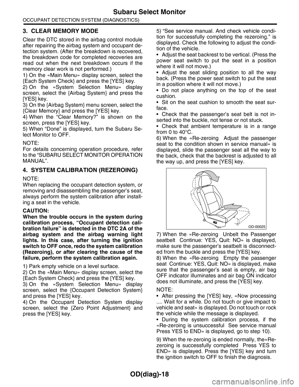
•Adjust the seat backrest to be vertical. (Press the
power seat switch to put the seat in a position
where it will not move.)
•Adjust the seat sliding position to all the way
back. (Press the power seat switch to put the seat
in a position where it will not move.)
•Do not place anything on the top of the seat
cushion.
•Sit on the seat cushion to smooth the seat sur-
face.
•Check that the passenger’s seat belt is not in-
serted into the buckle, not tense or not stuck.
•Check that ambient temperature is in a range
from 0 to 40°C.
6) When the «Re-zeroing Adjust the passenger
seat to the condition shown in service manual» is
displayed, slide the passenger seat all the way to
the back, check that the backrest is adjusted to all
the way up, and press the [YES] key.
7) When the «Re-zeroing Unbelt the Passenger
seatbelt Continue: YES, Quit: NO» is displayed,
make sure the passenger’s seatbelt is disconnect-
ed from the buckle and press the [YES] key.
8) When the «Re-zeroing Empty the passenger
seat Continue: YES, Quit: NO» is displayed, make
sure that the passenger’s seat is empty, air bag
OFF indicator illuminates and air bag ON indicator
does not illuminate, and press the [YES] key.
NOTE:
•After pressing the [YES] key, «Now processing
.... Wait for a while. Do not touch or give impact to
vehicle and seat» is displayed. Do not touch or rock
the vehicle while the message is displayed.
•During the system calibration process, if the
«Re-zeroing is unsuccessful See service manual
Press YES to END» is displayed, go to step 10).
9) When the re-zeroing is ended normally, the«Re-
zeroing is successfully completed Press YES to
END» is displayed. Press the [YES] key and turn
the ignition switch to OFF to finish the diagnosis.
OD-00025
Page 631 of 2453
SL-2
General Description
SECURITY AND LOCKS
1. General Description
A: COMPONENT
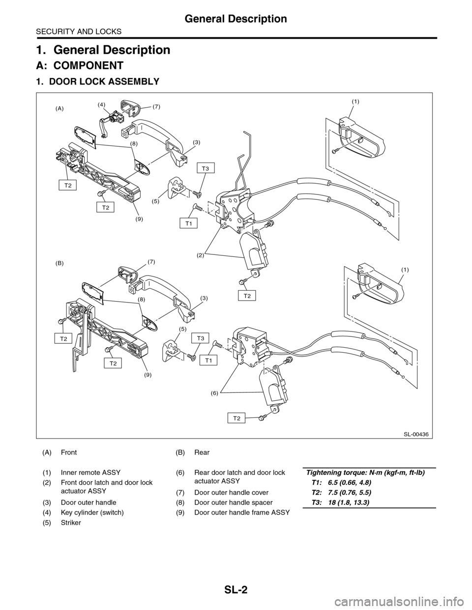
1. DOOR LOCK ASSEMBLY
(A) Front (B) Rear
(1) Inner remote ASSY (6) Rear door latch and door lock
actuator ASSY
Tightening torque: N·m (kgf-m, ft-lb)
(2) Front door latch and door lock
actuator ASSY
T1: 6.5 (0.66, 4.8)
(7) Door outer handle coverT2: 7.5 (0.76, 5.5)
(3) Door outer handle (8) Door outer handle spacerT3: 18 (1.8, 13.3)
(4) Key cylinder (switch) (9) Door outer handle frame ASSY
(5) Striker
SL-00436
(9)
T1
(B)
(A)
T3
(5)
(9)
(2)
(1)
(1)
T3
(5)
(6)
T2
T1
(3)
(7)(4)
(8)
T2
(3)
(7)
T2
T2
(8)T2
T2
Page 635 of 2453
SL-6
General Description
SECURITY AND LOCKS
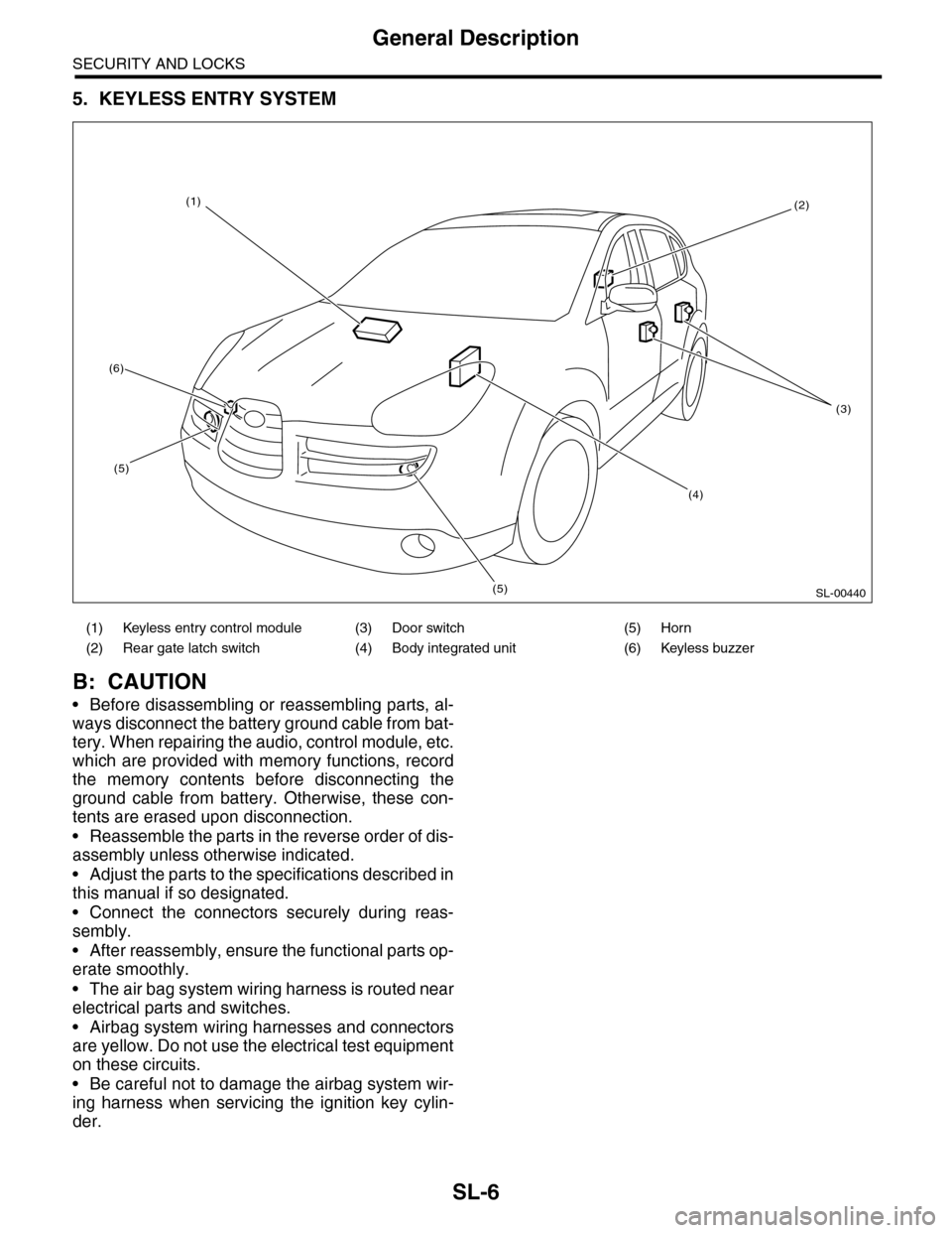
5. KEYLESS ENTRY SYSTEM
B: CAUTION
•Before disassembling or reassembling parts, al-
ways disconnect the battery ground cable from bat-
tery. When repairing the audio, control module, etc.
which are provided with memory functions, record
the memory contents before disconnecting the
ground cable from battery. Otherwise, these con-
tents are erased upon disconnection.
•Reassemble the parts in the reverse order of dis-
assembly unless otherwise indicated.
•Adjust the parts to the specifications described in
this manual if so designated.
•Connect the connectors securely during reas-
sembly.
•After reassembly, ensure the functional parts op-
erate smoothly.
•The air bag system wiring harness is routed near
electrical parts and switches.
•Airbag system wiring harnesses and connectors
are yellow. Do not use the electrical test equipment
on these circuits.
•Be careful not to damage the airbag system wir-
ing harness when servicing the ignition key cylin-
der.
(1) Keyless entry control module (3) Door switch (5) Horn
(2) Rear gate latch switch (4) Body integrated unit (6) Keyless buzzer
SL-00440
(2)
(3)
(4)
(5)
(5)
(6)
(1)
Page 636 of 2453
SL-7
General Description
SECURITY AND LOCKS
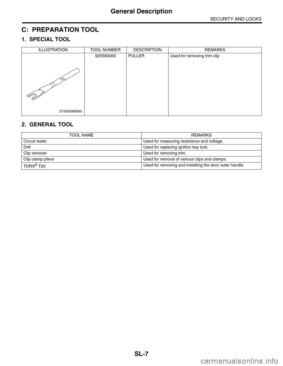
C: PREPARATION TOOL
1. SPECIAL TOOL
2. GENERAL TOOL
ILLUSTRATION TOOL NUMBER DESCRIPTION REMARKS
925580000 PULLER Used for removing trim clip
TOOL NAME REMARKS
Circuit tester Used for measuring resistance and voltage.
Drill Used for replacing ignition key lock.
Clip remover Used for removing trim.
Clip clamp pliers Used for removal of various clips and clamps.
TO RX® T20Used for removing and installing the door outer handle.
ST-925580000
Page 637 of 2453
SL-8
Door Lock Control System
SECURITY AND LOCKS
2. Door Lock Control System
A: WIRING DIAGRAM
1. DOOR LOCK CONTROL
B: INSPECTION
1. SYMPTOM CHART
2. CHECK FUSE
3. CHECK POWER SUPPLY & GROUND CIRCUIT
Symptom Repair order Reference
The door lock control system does
not operate.
1. Check the fuse.
2. Check the power supply and ground cir-
cuit for body integrated unit.
Lock Control System.>
3. Check the door lock switch and the circuit.
trol System.>
4. Check the door lock actuator and the cir-
cuit.
Door Lock Control System.>
The door lock switch does not oper-
ate.
Check the door lock switch.
trol System.>
A specific door lock actuator does
not operate.
Check the door lock actuator and circuit.
Door Lock Control System.>
Step Check Yes No
1CHECK FUSE.
Remove and visually check the fuse No. 3 (in
the fuse and relay box) and No. 7 (in the fuse
and relay box).
Is the fuse blown out? Replace the fuse
with a new one.
Check the power
supply and ground
circuit.
POWER SUPPLY
& GROUND CIR-
CUIT, INSPEC-
TION, Door Lock
Control System.>
Step Check Yes No
1CHECK POWER SUPPLY.
1) Disconnect the harness connector of body
integrated unit.
2) Measure the voltage between harness con-
nector terminal and chassis ground.
Connector & terminal
(i84) No. 34 (+) — Chassis ground (–):
(B281) No. 2 (+) — Chassis ground (– ):
Is the voltage more than 10 V? Go to step 2.Check the harness
for open or shor t
circuit between
body integrated
unit and fuse.
2CHECK GROUND CIRCUIT.
Measure the resistance between harness con-
nector terminal and chassis ground.
Connector & terminal
(B280) No. 22 — Chassis ground:
(B281) No. 8, 9 — Chassis ground:
Is the resistance less than 10
Ω?
The power supply
and ground circuit
are OK.
Repair the har-
ness.
Page 640 of 2453
SL-11
Keyless Entry System
SECURITY AND LOCKS
3. Keyless Entry System
A: WIRING DIAGRAM
1. KEYLESS ENTRY
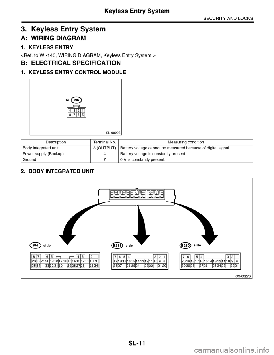
B: ELECTRICAL SPECIFICATION
1. KEYLESS ENTRY CONTROL MODULE
2. BODY INTEGRATED UNIT
SL-00228
43218765
i96To
Description Terminal No. Measuring condition
Body integrated unit 3 (OUTPUT) Battery voltage cannot be measured because of digital signal.
Pow er s up p ly ( B a cku p ) 4 B at t e r y vol t ag e i s c on s ta n tl y p r e se nt .
Ground 7 0 V is constantly present.
CS-00273
71928
61827
51741626152514241312231122
3102921
1820
B281side
72030
619291828
51741627152614132512241123
3102922
1821
B280side
82335
722342162033
51932183117301615291428
41327
312261121025
1924
i84side
Page 641 of 2453
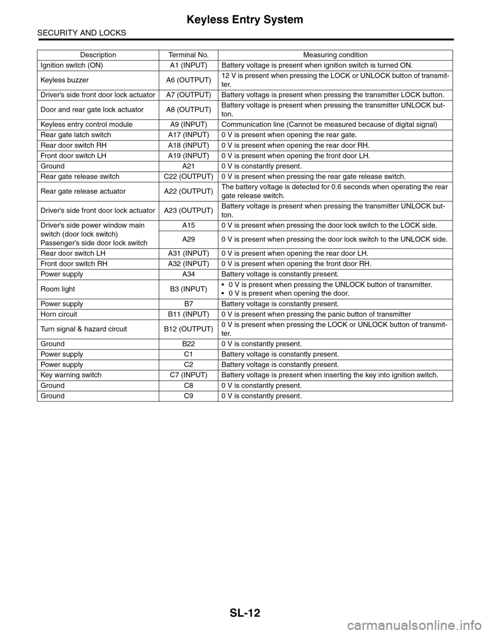
SL-12
Keyless Entry System
SECURITY AND LOCKS
Description Terminal No. Measuring condition
Ignition switch (ON) A1 (INPUT) Battery voltage is present when ignition switch is turned ON.
Keyless buzzer A6 (OUTPU T)12 V is present when pressing the LOCK or UNLOCK button of transmit-
ter.
Driver’s side front door lock actuator A7 (OUTPUT) Battery voltage is present when pressing the transmitter LOCK button.
Door and rear gate lock actuator A8 (OUTPUT)Battery voltage is present when pressing the transmitter UNLOCK but-
ton.
Keyless entr y control module A9 (INPUT) Communication line (Cannot be measured because of digital signal)
Rear gate latch switch A17 (INPUT) 0 V is present when opening the rear gate.
Rear door switch RH A18 (INPUT) 0 V is present when opening the rear door RH.
Fr o nt d oo r swi tc h L H A 19 ( I NP UT ) 0 V i s pr e se n t wh e n o p en in g th e f r o n t d oo r L H.
Ground A21 0 V is constantly present.
Rear gate release switch C22 (OUTPUT) 0 V is present when pressing the rear gate release switch.
Rear gate release actuator A22 (OUTPUT)The battery voltage is detected for 0.6 seconds when operating the rear
gate release switch.
Driver’s side front door lock actuator A23 (OUTPUT)Battery voltage is present when pressing the transmitter UNLOCK but-
ton.
Driver’s side power window main
switch (door lock switch)
Passenger’s side door lock sw itch
A15 0 V is present when pressing the door lock switch to the LOCK side.
A29 0 V is present when pressing the door lock switch to the UNLOCK side.
Rear door switch LH A31 (INPUT) 0 V is present when opening the rear door LH.
Fr o nt d oo r swi tc h RH A 32 ( I NP UT ) 0 V i s pr e se n t wh e n o p en in g th e f r o n t d oo r RH.
Pow er s up p ly A 34 B at t e r y vol t ag e i s c on s ta n tl y p r e se nt .
Room light B3 (INPUT)•0 V is present when pressing the UNLOCK button of transmitter.
•0 V is present when opening the door.
Pow er s up p ly B 7 B at t e r y vol t ag e i s c on s ta n tl y p r e se nt .
Horn circuit B11 (INPUT) 0 V is present when pressing the panic button of transmitter
Tu r n s i g n a l & h a z a r d c i r c u i t B 1 2 ( O U T P U T )0 V is present when pressing the LOCK or UNLOCK button of transmit-
ter.
Ground B22 0 V is constantly present.
Pow er s up p ly C 1 B at t e r y vol t ag e i s c on s ta n tl y p r e se nt .
Pow er s up p ly C 2 B at t e r y vol t ag e i s c on s ta n tl y p r e se nt .
Key war ning switch C7 (INPUT) Batter y voltage is present when inser ting the key into ignition switch.
Ground C8 0 V is constantly present.
Ground C9 0 V is constantly present.
Page 642 of 2453
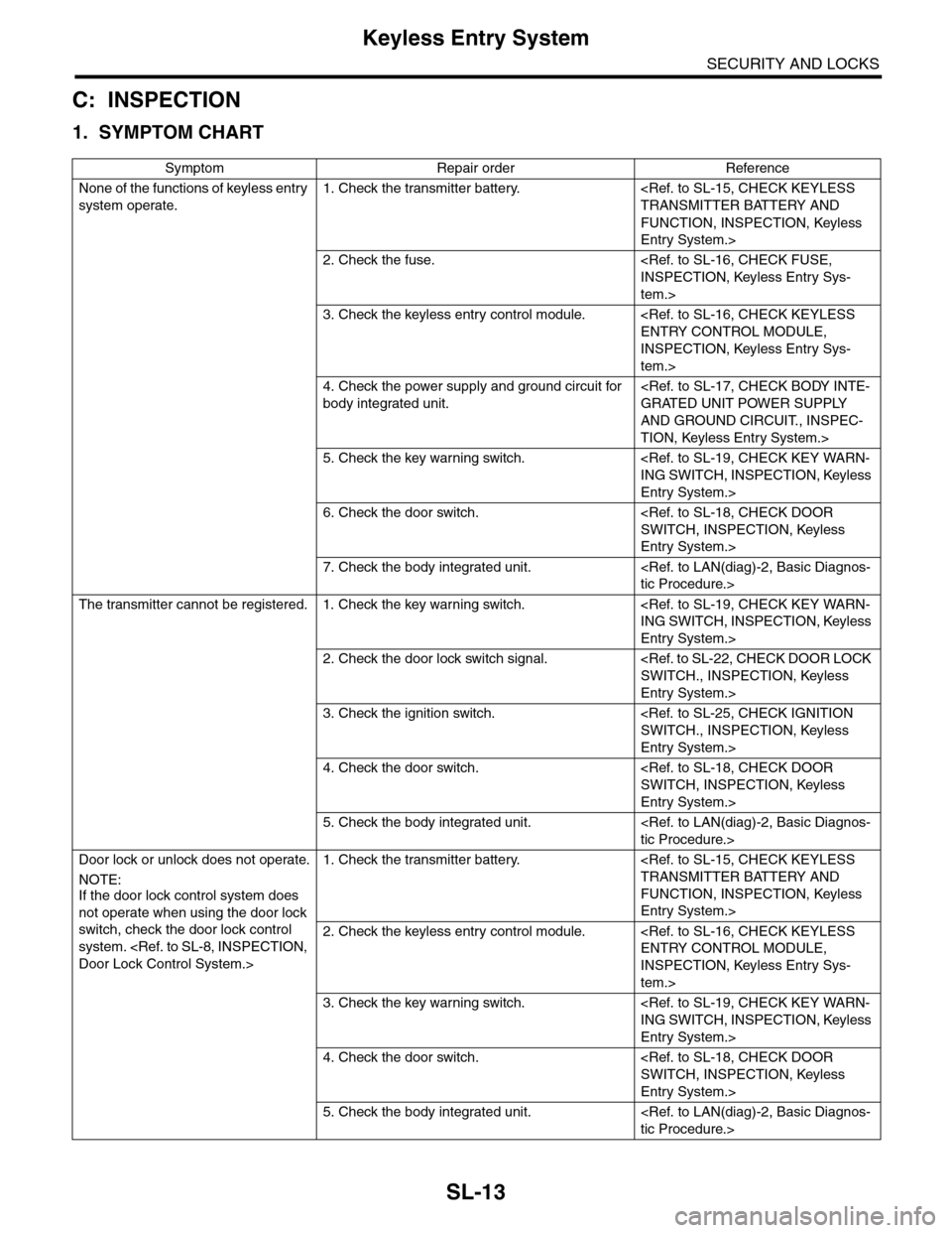
SL-13
Keyless Entry System
SECURITY AND LOCKS
C: INSPECTION
1. SYMPTOM CHART
Symptom Repair order Reference
None of the functions of keyless entry
system operate.
1. Check the transmitter battery.
FUNCTION, INSPECTION, Keyless
Entry System.>
2. Check the fuse.
tem.>
3. Check the keyless entry control module.
INSPECTION, Keyless Entry Sys-
tem.>
4. Check the power supply and ground circuit for
body integrated unit.
AND GROUND CIRCUIT., INSPEC-
TION, Keyless Entry System.>
5. Check the key warning switch.
Entry System.>
6. Check the door switch.
Entry System.>
7. Check the body integrated unit.
The transmitter cannot be registered. 1. Check the key warning switch.
Entry System.>
2. Check the door lock switch signal.
Entry System.>
3. Check the ignition switch.
Entry System.>
4. Check the door switch.
Entry System.>
5. Check the body integrated unit.
Door lock or unlock does not operate.
NOTE:If the door lock control system does
not operate when using the door lock
switch, check the door lock control
system.
1. Check the transmitter battery.
FUNCTION, INSPECTION, Keyless
Entry System.>
2. Check the keyless entry control module.
INSPECTION, Keyless Entry Sys-
tem.>
3. Check the key warning switch.
Entry System.>
4. Check the door switch.
Entry System.>
5. Check the body integrated unit.