Diff id SUBARU TRIBECA 2009 1.G Service Workshop Manual
[x] Cancel search | Manufacturer: SUBARU, Model Year: 2009, Model line: TRIBECA, Model: SUBARU TRIBECA 2009 1.GPages: 2453, PDF Size: 46.32 MB
Page 11 of 2453
AB-12
Inspection Locations After a Collision
AIRBAG SYSTEM
3. Inspection Locations After a
Collision
A: REPLACEMENT
Replace the following parts when the airbag is de-
ployed.
1. FRONT COLLISION
1) Driver’s airbag module
2) Passenger’s airbag module
3) Driver’s seat belt (Pretensioner)
4) Passenger’s seat belt (Pretensioner)
5) Airbag control module
6) Front sub sensor (L/R)
7) Roll connector
8) Instrument panel (for integrating with passen-
ger’s airbag module)
9) Passenger side seat cushion pad and frame as-
sembly
2. SIDE COLLISION
1) Airbag control module
2) Side airbag module (operating side seat back-
rest)
3) Side airbag sensor (operating side)
4) Curtain airbag module (operating side)
5) Curtain airbag sensor (operating side)
3. INSPECTION OF OTHER PARTS
Check for the following parts, and replace the dam-
aged parts with new parts.
1) Steering wheel and steering shaft
Check the steering shaft for mounting conditions
and deflection of front and rear, upward and down-
ward directions, and deflection of front and rear di-
rection with tilt lever released. (After a collision,
there is a good chance that the shock absorbing
part of steering shaft may have operated.)
2) Check the connectors of airbag module, preten-
sioner, etc. for damage, and also check each har-
ness for pinch and connector damage. Replace the
harness as a unit if damage is found.
3) Check the seat cushion frame, backrest, seat rail
and headrest for deformation, distortion, crack, and
installing condition and play.
4) For passengers seat, replace the seat cushion
frame assembly with new one if the seat cushion
frame is deformed or cracked.
5) If there are tears or loosening in the passenger
side seat cushion cover, it may interfere with the
proper operation of the passenger detection sys-
tem. Replace with a new cushion cover.
6) Be sure to perform the system calibration for the
occupant detection system after removing or re-
placing the passenger seat cushion cover. Failure
to do so may cause improper operation of the pas-
senger detection system.
TION, Subaru Select Monitor.>
7) Use the Subaru Select Monitor to check whether
the drivers seat position sensor and the drivers and
the front left/right seat belt buckle switches are op-
erating normally.
B: INSPECTION
If the vehicle is involved in a collision, even if it is a
slight collision, be sure to check the following sys-
tems.
1. DRIVER’S AIRBAG MODULE
1) Check for the following, and replace the dam-
aged parts with new parts.
•Airbag module is cracked or deformed.
•Harness and/or connector is cracked, deformed
or open. Harness wire is exposed.
•The module surface is fouled with grease, oil,
water or cleaning solvent.
2) When installing a new driver’s airbag module,
check for the following, and replace the damaged
parts with new parts.
•The steering wheel is in the way, making it diffi-
cult to install the airbag module.
•The clearance between the driver’s airbag mod-
ule and steering wheel is not constant.
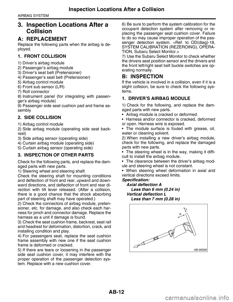
•When steering wheel deformation in axial and
vertical directions exceed limits.
Specification:
Axial deflection A
Less than 6 mm (0.24 in)
Vertical deflection L
Less than 7 mm (0.28 in)
AB-00028
L
A
Page 195 of 2453
ET-9
Rear Entertainment System
ENTERTAINMENT
7. Rear Entertainment System
A: WIRING DIAGRAM
B: INSPECTION
1. CHECK THE DVD-ROM.
Insert a region code 1 DVD-ROM, and check that the display shows images from the DVD when playing back
the media.
NOTE:
Region code 1 is a code for North American DVD-ROM discs. DVD-ROMs of different region codes will not
be played back.
Standard value: Image from DVD should be displayed.
OK: Normal
NG: If the images from the DVD is not displayed, check whether the DVD-ROM is set in the rear entertain-
ment system, whether the correct side is set, type of the DVD-ROM, the existence of any scratches, etc. If
there are no problems on the DVD-ROM, the main body is defective.
NOTE:
The rear entertainment system is not compatible with MP3 files or DVD-Audio.
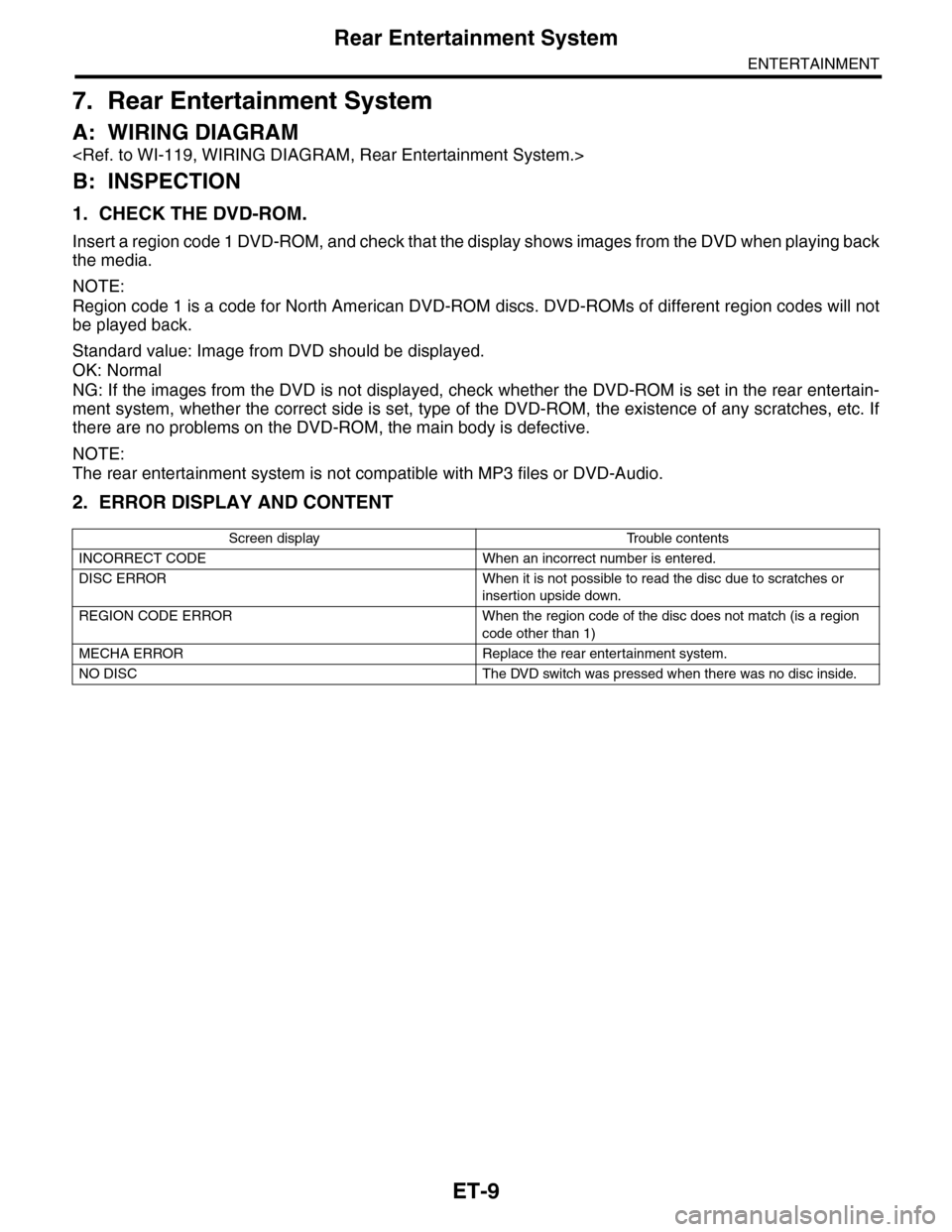
2. ERROR DISPLAY AND CONTENT
Screen display Trouble contents
INCORRECT CODE When an incorrect number is entered.
DISC ERROR When it is not possible to read the disc due to scratches or
insertion upside down.
REGION CODE ERROR When the region code of the disc does not match (is a region
code other than 1)
MECHA ERROR Replace the rear entertainment system.
NO DISC The DVD switch was pressed when there was no disc inside.
Page 274 of 2453
EI-32
Side Garnish
EXTERIOR/INTERIOR TRIM
10.Side Garnish
A: REMOVAL
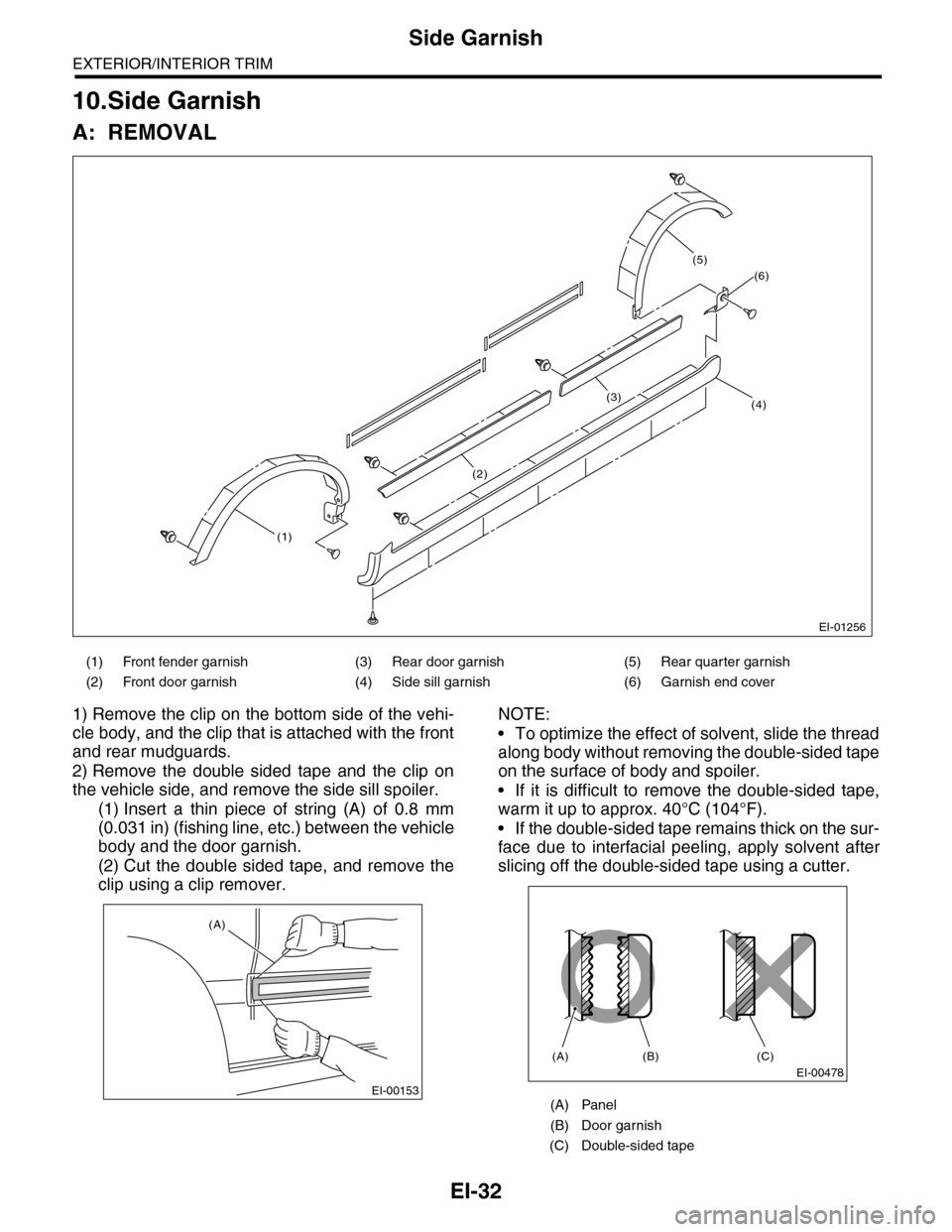
1) Remove the clip on the bottom side of the vehi-
cle body, and the clip that is attached with the front
and rear mudguards.
2) Remove the double sided tape and the clip on
the vehicle side, and remove the side sill spoiler.
(1) Insert a thin piece of string (A) of 0.8 mm
(0.031 in) (fishing line, etc.) between the vehicle
body and the door garnish.
(2) Cut the double sided tape, and remove the
clip using a clip remover.
NOTE:
•To optimize the effect of solvent, slide the thread
along body without removing the double-sided tape
on the surface of body and spoiler.
•If it is difficult to remove the double-sided tape,
warm it up to approx. 40°C (104°F).
•If the double-sided tape remains thick on the sur-
face due to interfacial peeling, apply solvent after
slicing off the double-sided tape using a cutter.
(1) Front fender garnish (3) Rear door garnish (5) Rear quarter garnish
(2) Front door garnish (4) Side sill garnish (6) Garnish end cover
EI-01256
(1)
(2)
(3)
(6)
(4)
(5)
EI-00153
(A)
(A) Panel
(B) Door garnish
(C) Double-sided tape
EI-00478
(A) (B) (C)
Page 328 of 2453
AC-2
General Description
HVAC SYSTEM (HEATER, VENTILATOR AND A/C)
1. General Description
A: SPECIFICATION
1. HEATER SYSTEM
2. A/C SYSTEM
•Single A/C model (front only)
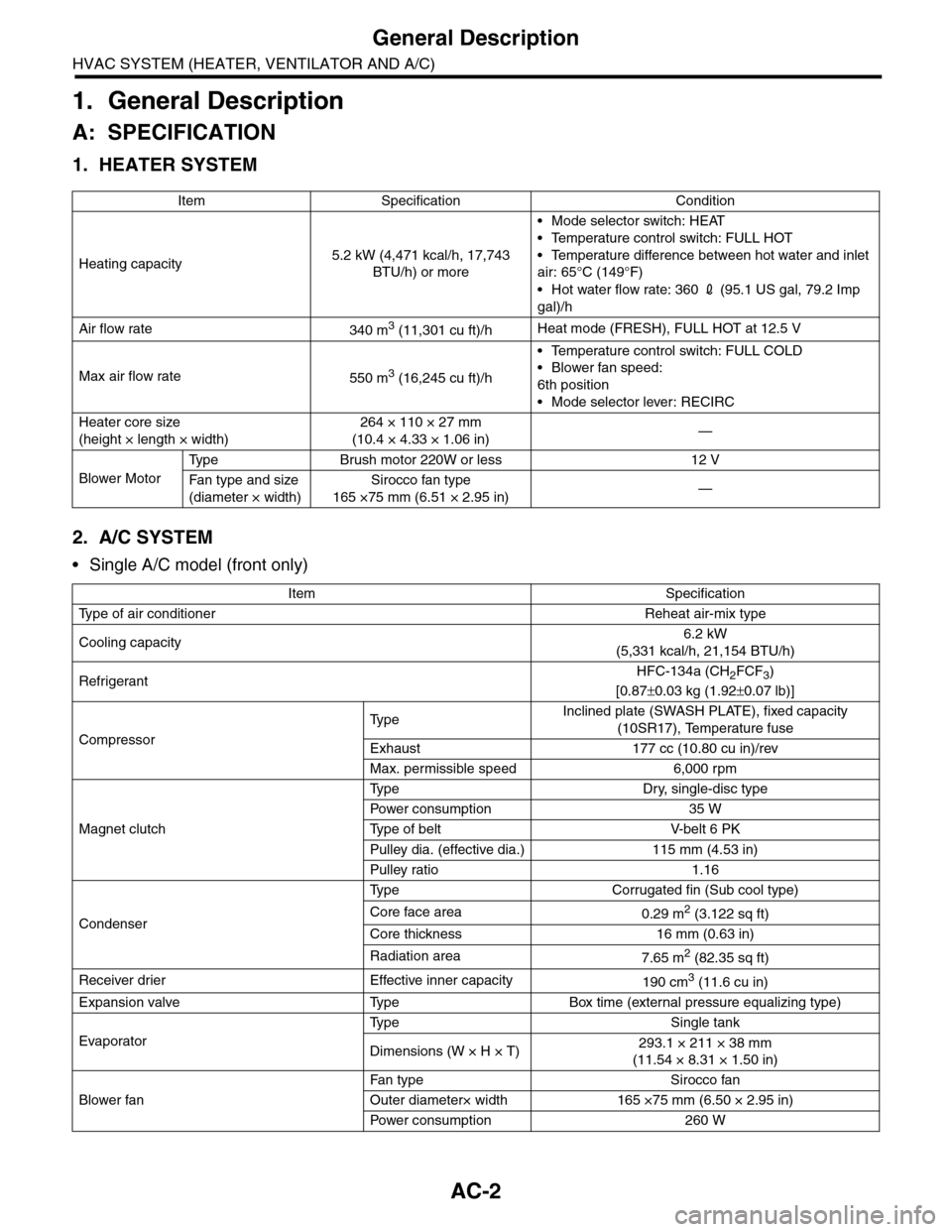
Item Specification Condition
Heating capacity5.2 kW (4,471 kcal/h, 17,743
BTU/h) or more
•Mode selector switch: HEAT
•Temperature control switch: FULL HOT
•Temperature difference between hot water and inlet
air: 65°C (149°F)
•Hot water flow rate: 360 2 (95.1 US gal, 79.2 Imp
gal)/h
Air flow rate340 m3 (11,301 cu ft)/hHeat mode (FRESH), FULL HOT at 12.5 V
Max air flow rate550 m3 (16,245 cu ft)/h
•Temperature control switch: FULL COLD
•Blower fan speed:
6th position
•Mode selector lever: RECIRC
Heater core size
(height × length × width)
264 × 110 × 27 mm
(10.4 × 4.33 × 1.06 in)—
Blower Motor
Ty p e B r u s h m o t o r 2 2 0 W o r l e s s 1 2 V
Fa n t y pe an d si ze
(diameter × width)
Sirocco fan type
165 ×75 mm (6.51 × 2.95 in)—
Item Specification
Ty p e o f a i r c o n d i t i o n e r R e h e a t a i r - m i x t y p e
Cooling capacity6.2 kW
(5,331 kcal/h, 21,154 BTU/h)
RefrigerantHFC-134a (CH2FCF3)
[0.87±0.03 kg (1.92±0.07 lb)]
Compressor
Ty p eInclined plate (SWASH PLATE), fixed capacity
(10SR17), Temperature fuse
Exhaust 177 cc (10.80 cu in)/rev
Max. permissible speed 6,000 rpm
Magnet clutch
Ty p e D r y, s i n g l e - d i s c t y p e
Powe r c on su mp t i on 35 W
Ty p e o f b e l t V- b e l t 6 P K
Pulley dia. (effective dia.) 115 mm (4.53 in)
Pulley ratio 1.16
Condenser
Ty p e C o r r u g a t e d f i n ( S u b c o o l t y p e )
Core face area0.29 m2 (3.122 sq ft)
Core thickness 16 mm (0.63 in)
Radiation area7.65 m2 (82.35 sq ft)
Receiver drier Effective inner capacity190 cm3 (11.6 cu in)
Expansion valve Type Box time (external pressure equalizing type)
Evaporator
Ty p e S i n g l e t a n k
Dimensions (W × H × T)293.1 × 211 × 38 mm
(11.54 × 8.31 × 1.50 in)
Blower fan
Fan t yp e S i r oc co fa n
Outer diameter× width 165 ×75 mm (6.50 × 2.95 in)
Powe r c on su mp t i on 2 60 W
Page 340 of 2453
AC-14
General Description
HVAC SYSTEM (HEATER, VENTILATOR AND A/C)
C: CAUTION
1. HFC-134A A/C SYSTEM
•The cooling system components for the HFC-
134a system such as the refrigerant and compres-
sor oil are different from the conventional CFC-12
system components and they are incompatible with
each other.
•Vehicles with the HFC-134a system can be iden-
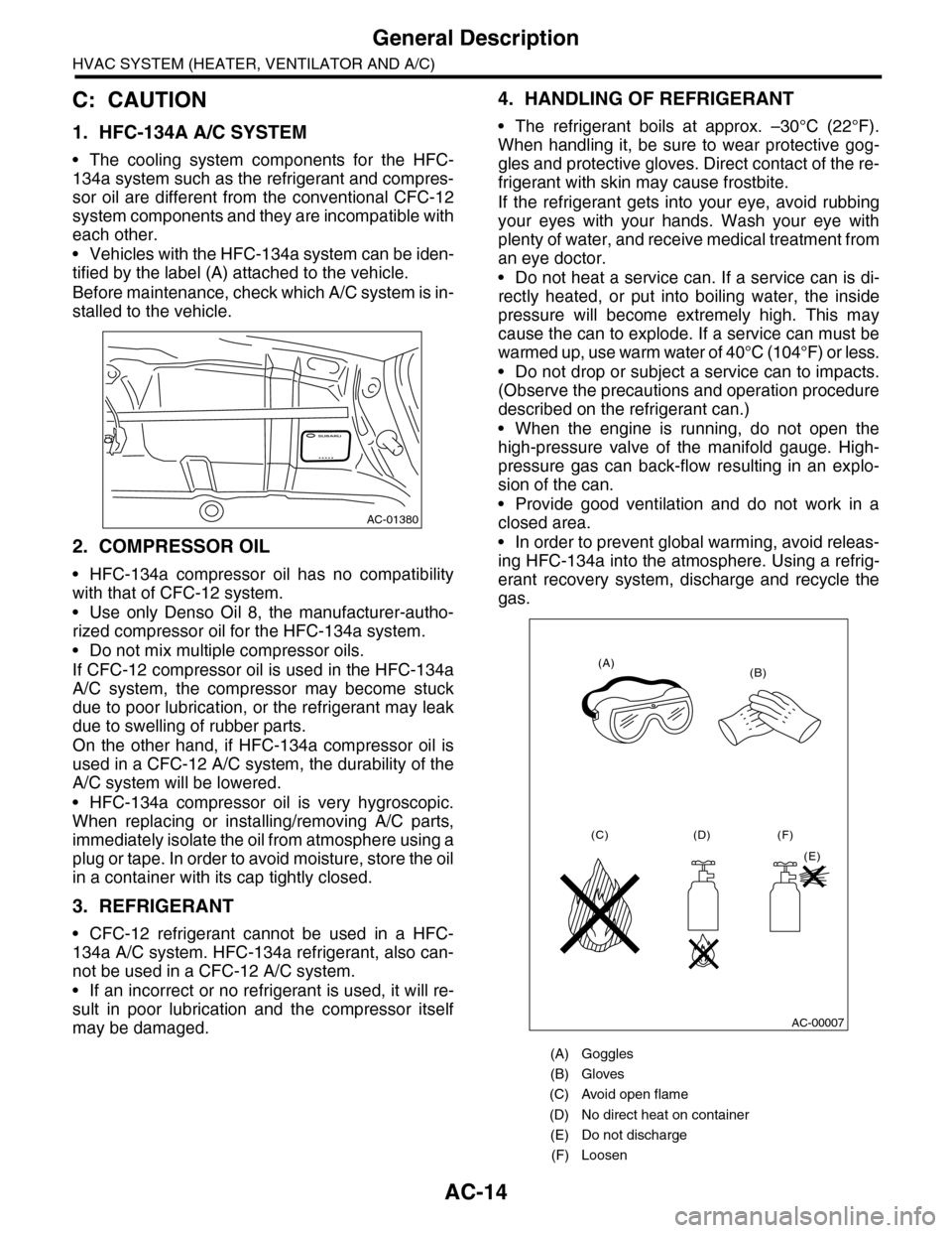
tified by the label (A) attached to the vehicle.
Before maintenance, check which A/C system is in-
stalled to the vehicle.
2. COMPRESSOR OIL
•HFC-134a compressor oil has no compatibility
with that of CFC-12 system.
•Use only Denso Oil 8, the manufacturer-autho-
rized compressor oil for the HFC-134a system.
•Do not mix multiple compressor oils.
If CFC-12 compressor oil is used in the HFC-134a
A/C system, the compressor may become stuck
due to poor lubrication, or the refrigerant may leak
due to swelling of rubber parts.
On the other hand, if HFC-134a compressor oil is
used in a CFC-12 A/C system, the durability of the
A/C system will be lowered.
•HFC-134a compressor oil is very hygroscopic.
When replacing or installing/removing A/C parts,
immediately isolate the oil from atmosphere using a
plug or tape. In order to avoid moisture, store the oil
in a container with its cap tightly closed.
3. REFRIGERANT
•CFC-12 refrigerant cannot be used in a HFC-
134a A/C system. HFC-134a refrigerant, also can-
not be used in a CFC-12 A/C system.
•If an incorrect or no refrigerant is used, it will re-
sult in poor lubrication and the compressor itself
may be damaged.
4. HANDLING OF REFRIGERANT
•The refrigerant boils at approx. –30°C (22°F).
When handling it, be sure to wear protective gog-
gles and protective gloves. Direct contact of the re-
frigerant with skin may cause frostbite.
If the refrigerant gets into your eye, avoid rubbing
your eyes with your hands. Wash your eye with
plenty of water, and receive medical treatment from
an eye doctor.
•Do not heat a service can. If a service can is di-
rectly heated, or put into boiling water, the inside
pressure will become extremely high. This may
cause the can to explode. If a service can must be
warmed up, use warm water of 40°C (104°F) or less.
•Do not drop or subject a service can to impacts.
(Observe the precautions and operation procedure
described on the refrigerant can.)
•When the engine is running, do not open the
high-pressure valve of the manifold gauge. High-
pressure gas can back-flow resulting in an explo-
sion of the can.
•Provide good ventilation and do not work in a
closed area.
•In order to prevent global warming, avoid releas-
ing HFC-134a into the atmosphere. Using a refrig-
erant recovery system, discharge and recycle the
gas.
AC-01380
(A) Goggles
(B) Gloves
(C) Avoid open flame
(D) No direct heat on container
(E) Do not discharge
(F) Loosen
(A)(B)
(C) (D)
(E)
(F)
AC-00007
Page 390 of 2453
AC(diag)-13
Diagnostic Chart for Self-diagnosis
HVAC SYSTEM (AUTO A/C) (DIAGNOSTICS)
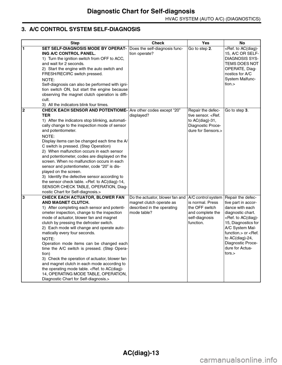
3. A/C CONTROL SYSTEM SELF-DIAGNOSIS
Step Check Yes No
1SET SELF-DIAGNOSIS MODE BY OPERAT-
ING A/C CONTROL PANEL.
1) Turn the ignition switch from OFF to ACC,
and wait for 2 seconds.
2) Start the engine with the auto switch and
FRESH/RECIRC switch pressed.
NOTE:
Self-diagnosis can also be performed with igni-
tion switch ON, but start the engine because
observing the magnet clutch operation is diffi-
cult.
3) All the indicators blink four times.
Does the self-diagnosis func-
tion operate?
Go to step 2.
DIAGNOSIS SYS-
TEMS DOES NOT
OPERATE, Diag-
nostics for A/C
System Malfunc-
tion.>
2CHECK EACH SENSOR AND POTENTIOME-
TER
1) After the indicators stop blinking, automati-
cally change to the inspection mode of sensor
and potentiometer.
NOTE:
Display items can be changed each time the A/
C switch is pressed. (Step Operation)
2) When malfunction occurs in each sensor
and potentiometer, codes are displayed on the
screen. When no malfunction occurs in each
sensor and potentiometer, code “20” is dis-
played on the screen.
3) Identify the defective sensor according to
the sensor check table.
nostic Chart for Self-diagnosis.>
Are other codes except “20”
displayed?
Repair the defec-
tive sensor.
Diagnostic Proce-
dure for Sensors.>
Go to step 3.
3CHECK EACH ACTUATOR, BLOWER FAN
AND MAGNET CLUTCH.
1) After completing each sensor and potenti-
ometer inspection, change to the inspection
mode of actuator, blower fan and magnet
clutch by pressing the defroster switch.
2) Each mode will change and operate auto-
matically every four seconds.
NOTE:
Operation mode items can be changed each
time the A/C switch is pressed. (Step Opera-
tion)
3) Check the operation of actuator, blower fan
and magnet clutch in each mode according to
the operating mode table.
Diagnostic Chart for Self-diagnosis.>
Do the actuator, blower fan and
magnet clutch operate as
described in the operating
mode table?
A/C control system
is normal. Press
the OFF switch
and complete the
self-diagnosis
function.
Repair the defec-
tive par t in accor-
dance with each
diagnostic chart.
A/C System Mal-
function.> or
Diagnostic Proce-
dure for Actua-
tors.>
Page 419 of 2453
IM (diag)-3
General Description
IMMOBILIZER (DIAGNOSTICS)
2. General Description
A: CAUTION
CAUTION:
•The airbag system wiring harnesses and con-
nectors are yellow. Do not use electrical test
equipment on these circuits.
•Be careful not to damage the airbag system
wiring harness.
•While diagnostic items are being checked, do
not operate radios, portable telephones, etc.
which emit electromagnetic waves near or in-
side the vehicle.
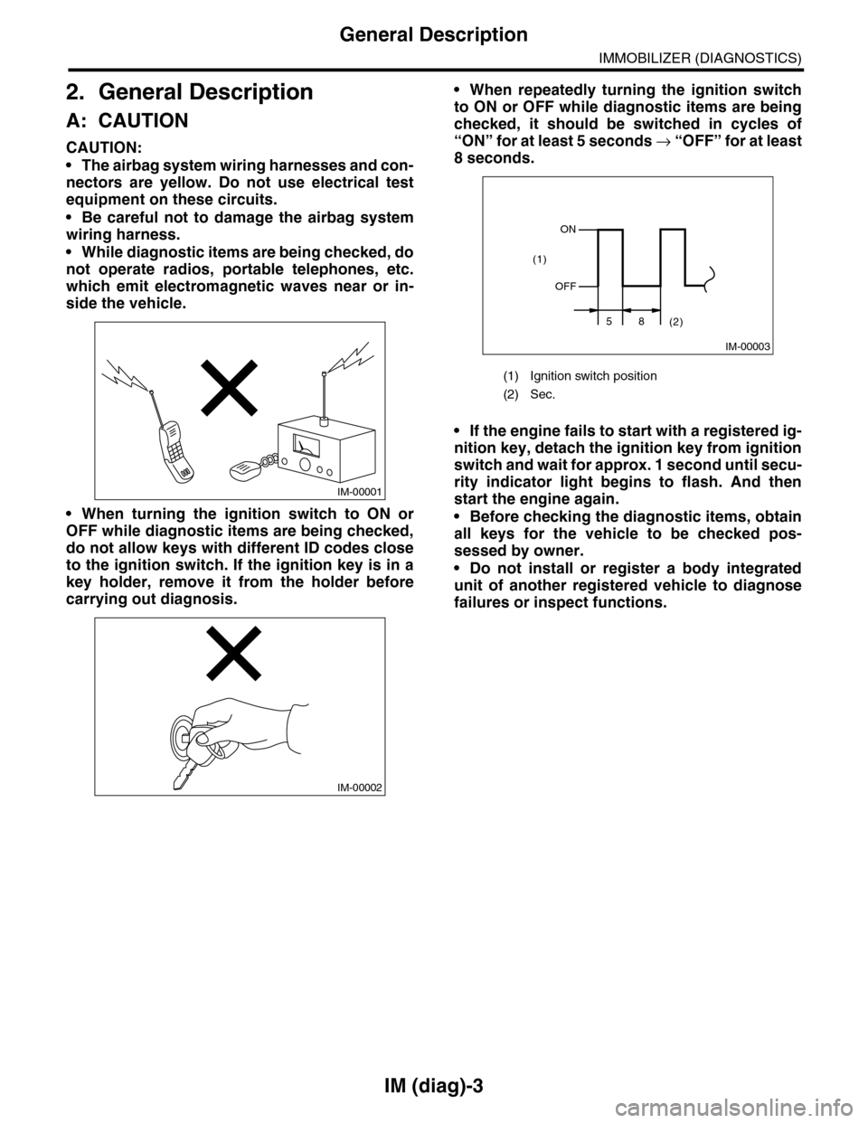
•When turning the ignition switch to ON or
OFF while diagnostic items are being checked,
do not allow keys with different ID codes close
to the ignition switch. If the ignition key is in a
key holder, remove it from the holder before
carrying out diagnosis.
•When repeatedly turning the ignition switch
to ON or OFF while diagnostic items are being
checked, it should be switched in cycles of
“ON” for at least 5 seconds → “O F F ” fo r a t le a s t
8 seconds.
•If the engine fails to start with a registered ig-
nition key, detach the ignition key from ignition
switch and wait for approx. 1 second until secu-
rity indicator light begins to flash. And then
start the engine again.
•Before checking the diagnostic items, obtain
all keys for the vehicle to be checked pos-
sessed by owner.
•Do not install or register a body integrated
unit of another registered vehicle to diagnose
failures or inspect functions.
IM-00001
IM-00002
(1) Ignition switch position
(2) Sec.
IM-00003
ON
OFF
58(2)
(1)
Page 441 of 2453
IDI-2
General Description
INSTRUMENTATION/DRIVER INFO
1. General Description
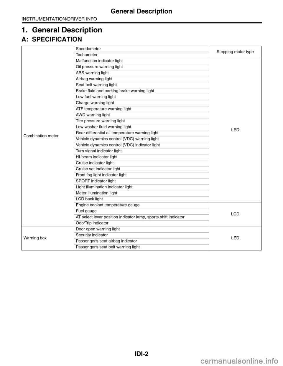
A: SPECIFICATION
Combination meter
SpeedometerStepping motor typeTa c h o m e t e r
Malfunction indicator light
LED
Oil pressure warning light
ABS warning light
Airbag warning light
Seat belt warning light
Brake fluid and parking brake warning light
Low fuel warning light
Charge warning light
AT F t e m p e r a t u r e w a r n i n g l i g h t
AW D war n in g l i gh t
Tire pressure warning light
Low washer fluid warning light
Rear differential oil temperature warning light
Ve h i c l e d y n a m i c s c o n t r o l ( V D C ) w a r n i n g l i g h t
Ve h i c l e d y n a m i c s c o n t r o l ( V D C ) i n d i c a t o r l i g h t
Tu r n s i g n a l i n d i c a t o r l i g h t
HI-beam indicator light
Cruise indicator light
Cruise set indicator light
Fr o nt fog li g ht i nd i ca to r li g ht
SPORT indicator light
Light illumination indicator light
Meter illumination light
LCD back light
Engine coolant temperature gauge
LCDFuel gauge
AT s e l e c t l e v e r p o s i t i o n i n d i c a t o r l a m p , s p o r t s s h i f t i n d i c a t o r
Odo/Trip indicator
Wa r ni n g b ox
Door open warning light
LEDSecurity indicator
Passenger’s seat airbag indicator
Passenger’s seat belt war ning light
Page 461 of 2453
LAN(diag)-5
General Description
LAN SYSTEM (DIAGNOSTICS)
3. General Description
A: CAUTION
1. SRS AIRBAG SYSTEM
Airbag system wiring harness is routed near the
body integrated unit and twisted pair line.
CAUTION:
•All airbag system wiring harness and con-
nectors are colored yellow. Do not use the elec-
trical test equipment on these circuits.
•Be careful not to damage the airbag system
wiring harness when servicing the body inte-
grated unit and LAN system.
•Refer to “Airbag System” when disconnect-
ing the air bag system connector.
2. LAN SYSTEM
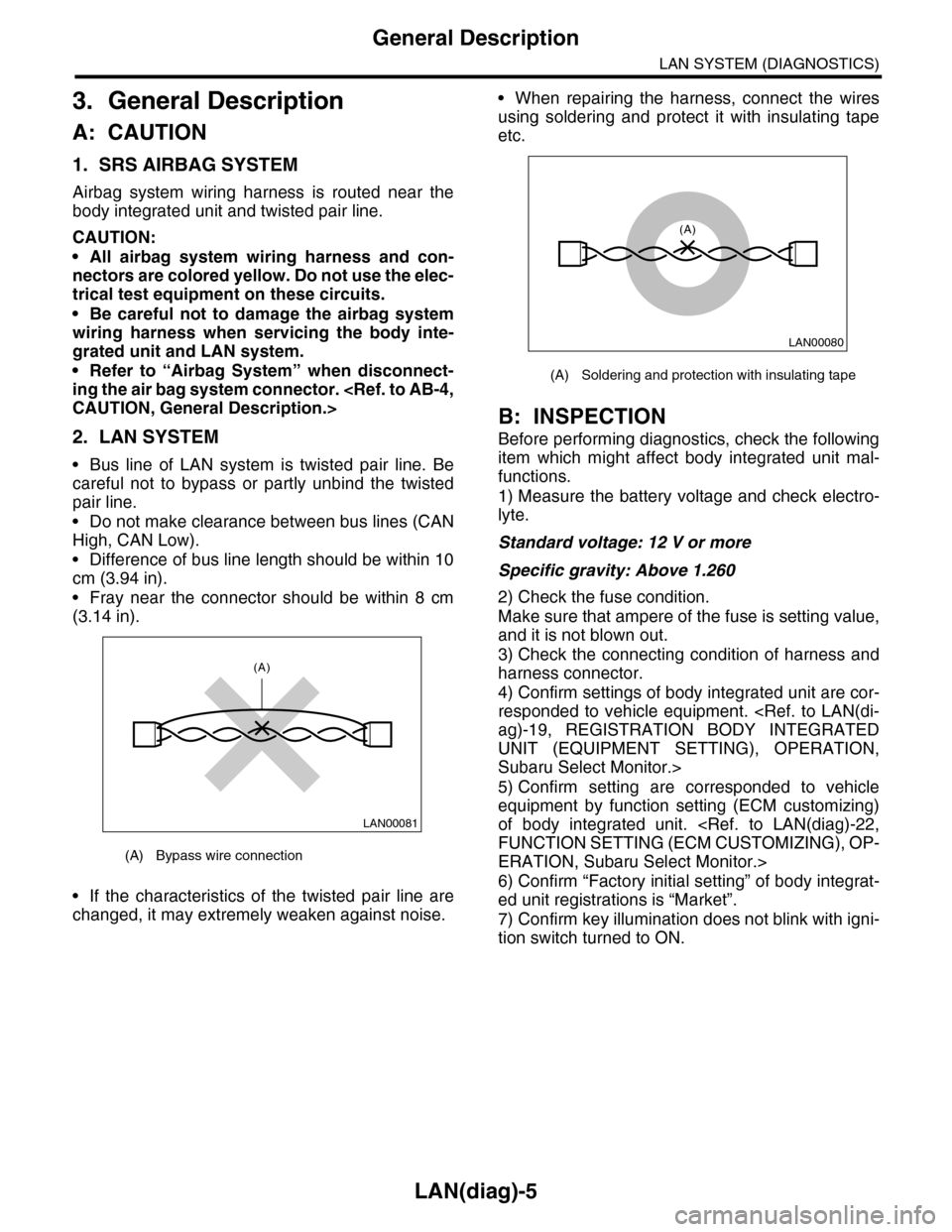
•Bus line of LAN system is twisted pair line. Be
careful not to bypass or partly unbind the twisted
pair line.
•Do not make clearance between bus lines (CAN
High, CAN Low).
•Difference of bus line length should be within 10
cm (3.94 in).
•Fray near the connector should be within 8 cm
(3.14 in).
•If the characteristics of the twisted pair line are
changed, it may extremely weaken against noise.
•When repairing the harness, connect the wires
using soldering and protect it with insulating tape
etc.
B: INSPECTION
Before performing diagnostics, check the following
item which might affect body integrated unit mal-
functions.
1) Measure the battery voltage and check electro-
lyte.
Standard voltage: 12 V or more
Specific gravity: Above 1.260
2) Check the fuse condition.
Make sure that ampere of the fuse is setting value,
and it is not blown out.
3) Check the connecting condition of harness and
harness connector.
4) Confirm settings of body integrated unit are cor-
responded to vehicle equipment.
UNIT (EQUIPMENT SETTING), OPERATION,
Subaru Select Monitor.>
5) Confirm setting are corresponded to vehicle
equipment by function setting (ECM customizing)
of body integrated unit.
ERATION, Subaru Select Monitor.>
6) Confirm “Factory initial setting” of body integrat-
ed unit registrations is “Market”.
7) Confirm key illumination does not blink with igni-
tion switch turned to ON.
(A) Bypass wire connection
LAN00081
(A)
(A) Soldering and protection with insulating tape
LAN00080
(A)
Page 466 of 2453
LAN(diag)-10
Control Module I/O Signal
LAN SYSTEM (DIAGNOSTICS)
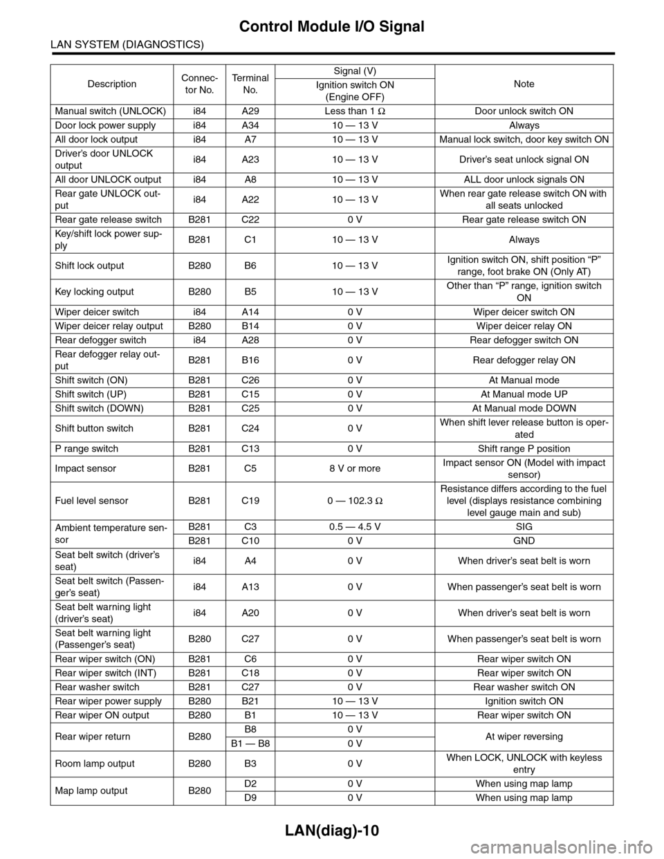
Manual switch (UNLOCK) i84 A29 Less than 1 ΩDoor unlock switch ON
Door lock power supply i84 A34 10 — 13 V Always
All door lock output i84 A7 10 — 13 V Manual lock switch, door key switch ON
Driver’s door UNLOCK
outputi84 A23 10 — 13 V Driver’s seat unlock signal ON
All door UNLOCK output i84 A8 10 — 13 V ALL door unlock signals ON
Rear gate UNLOCK out-
puti84 A22 10 — 13 VWhen rear gate release switch ON with
all seats unlocked
Rear gate release switch B281 C22 0 V Rear gate release switch ON
Key/shift lock power sup-
plyB281 C1 10 — 13 V Always
Shift lock output B280 B6 10 — 13 VIgnition switch ON, shift position “P”
range, foot brake ON (Only AT)
Key locking output B280 B5 10 — 13 VOther than “P” range, ignition switch
ON
Wiper deicer switch i84 A14 0 V Wiper deicer switch ON
Wiper deicer relay output B280 B14 0 V Wiper deicer relay ON
Rear defogger switch i84 A28 0 V Rear defogger switch ON
Rear defogger relay out-
putB281 B16 0 V Rear defogger relay ON
Shift switch (ON) B281 C26 0 V At Manual mode
Shift switch (UP) B281 C15 0 V At Manual mode UP
Shift switch (DOWN) B281 C25 0 V At Manual mode DOWN
Shift button switch B281 C24 0 VWhen shift lever release button is oper-
ated
P range switch B281 C13 0 V Shift range P position
Impact sensor B281 C5 8 V or moreImpact sensor ON (Model with impact
sensor)
Fuel level sensor B281 C19 0 — 102.3 Ω
Resistance differs according to the fuel
level (displays resistance combining
level gauge main and sub)
Ambient temperature sen-
sor
B281 C3 0.5 — 4.5 V SIG
B281 C10 0 V GND
Seat belt switch (driver’s
seat)i84 A4 0 V When driver’s seat belt is worn
Seat belt switch (Passen-
ger’s seat)i84 A13 0 V When passenger’s seat belt is worn
Seat belt warning light
(driver’s seat)i84 A20 0 V When driver’s seat belt is worn
Seat belt warning light
(Passenger’s seat)B280 C27 0 V When passenger’s seat belt is worn
Rear wiper switch (ON) B281 C6 0 V Rear wiper switch ON
Rear wiper switch (INT) B281 C18 0 V Rear wiper switch ON
Rear washer switch B281 C27 0 V Rear washer switch ON
Rear wiper power supply B280 B21 10 — 13 V Ignition switch ON
Rear wiper ON output B280 B1 10 — 13 V Rear wiper switch ON
Rear wiper return B280B8 0 VAt wiper reversingB1 — B8 0 V
Room lamp output B280 B3 0 VWhen LOCK, UNLOCK with keyless
entry
Map lamp output B280D2 0 V When using map lamp
D9 0 V When using map lamp
DescriptionConnec-
tor No.
Te r m i n a l
No.
Signal (V)
NoteIgnition switch ON
(Engine OFF)