Oil spec SUBARU TRIBECA 2009 1.G Service Workshop Manual
[x] Cancel search | Manufacturer: SUBARU, Model Year: 2009, Model line: TRIBECA, Model: SUBARU TRIBECA 2009 1.GPages: 2453, PDF Size: 46.32 MB
Page 4 of 2453
AB-5
General Description
AIRBAG SYSTEM
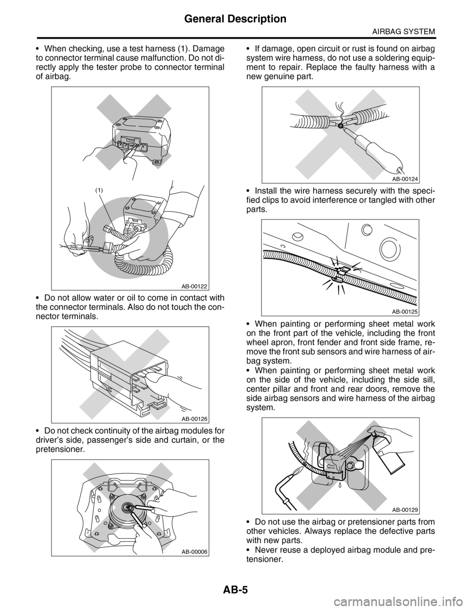
•When checking, use a test harness (1). Damage
to connector terminal cause malfunction. Do not di-
rectly apply the tester probe to connector terminal
of airbag.
•Do not allow water or oil to come in contact with
the connector terminals. Also do not touch the con-
nector terminals.
•Do not check continuity of the airbag modules for
driver’s side, passenger’s side and curtain, or the
pretensioner.
•If damage, open circuit or rust is found on airbag
system wire harness, do not use a soldering equip-
ment to repair. Replace the faulty harness with a
new genuine part.
•Install the wire harness securely with the speci-
fied clips to avoid interference or tangled with other
parts.
•When painting or performing sheet metal work
on the front part of the vehicle, including the front
wheel apron, front fender and front side frame, re-
move the front sub sensors and wire harness of air-
bag system.
•When painting or performing sheet metal work
on the side of the vehicle, including the side sill,
center pillar and front and rear doors, remove the
side airbag sensors and wire harness of the airbag
system.
•Do not use the airbag or pretensioner parts from
other vehicles. Always replace the defective parts
with new parts.
•Never reuse a deployed airbag module and pre-
tensioner.
AB-00122
(1)
AB-00126
AB-00006
AB-00124
AB-00125
AB-00129
Page 11 of 2453
AB-12
Inspection Locations After a Collision
AIRBAG SYSTEM
3. Inspection Locations After a
Collision
A: REPLACEMENT
Replace the following parts when the airbag is de-
ployed.
1. FRONT COLLISION
1) Driver’s airbag module
2) Passenger’s airbag module
3) Driver’s seat belt (Pretensioner)
4) Passenger’s seat belt (Pretensioner)
5) Airbag control module
6) Front sub sensor (L/R)
7) Roll connector
8) Instrument panel (for integrating with passen-
ger’s airbag module)
9) Passenger side seat cushion pad and frame as-
sembly
2. SIDE COLLISION
1) Airbag control module
2) Side airbag module (operating side seat back-
rest)
3) Side airbag sensor (operating side)
4) Curtain airbag module (operating side)
5) Curtain airbag sensor (operating side)
3. INSPECTION OF OTHER PARTS
Check for the following parts, and replace the dam-
aged parts with new parts.
1) Steering wheel and steering shaft
Check the steering shaft for mounting conditions
and deflection of front and rear, upward and down-
ward directions, and deflection of front and rear di-
rection with tilt lever released. (After a collision,
there is a good chance that the shock absorbing
part of steering shaft may have operated.)
2) Check the connectors of airbag module, preten-
sioner, etc. for damage, and also check each har-
ness for pinch and connector damage. Replace the
harness as a unit if damage is found.
3) Check the seat cushion frame, backrest, seat rail
and headrest for deformation, distortion, crack, and
installing condition and play.
4) For passengers seat, replace the seat cushion
frame assembly with new one if the seat cushion
frame is deformed or cracked.
5) If there are tears or loosening in the passenger
side seat cushion cover, it may interfere with the
proper operation of the passenger detection sys-
tem. Replace with a new cushion cover.
6) Be sure to perform the system calibration for the
occupant detection system after removing or re-
placing the passenger seat cushion cover. Failure
to do so may cause improper operation of the pas-
senger detection system.
TION, Subaru Select Monitor.>
7) Use the Subaru Select Monitor to check whether
the drivers seat position sensor and the drivers and
the front left/right seat belt buckle switches are op-
erating normally.
B: INSPECTION
If the vehicle is involved in a collision, even if it is a
slight collision, be sure to check the following sys-
tems.
1. DRIVER’S AIRBAG MODULE
1) Check for the following, and replace the dam-
aged parts with new parts.
•Airbag module is cracked or deformed.
•Harness and/or connector is cracked, deformed
or open. Harness wire is exposed.
•The module surface is fouled with grease, oil,
water or cleaning solvent.
2) When installing a new driver’s airbag module,
check for the following, and replace the damaged
parts with new parts.
•The steering wheel is in the way, making it diffi-
cult to install the airbag module.
•The clearance between the driver’s airbag mod-
ule and steering wheel is not constant.
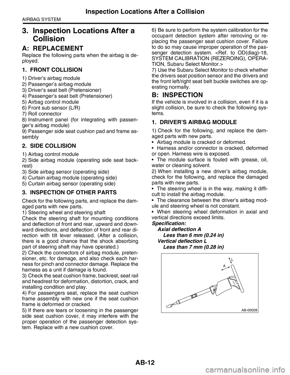
•When steering wheel deformation in axial and
vertical directions exceed limits.
Specification:
Axial deflection A
Less than 6 mm (0.24 in)
Vertical deflection L
Less than 7 mm (0.28 in)
AB-00028
L
A
Page 29 of 2453
AB(diag)-5
General Description
AIRBAG SYSTEM (DIAGNOSTICS)
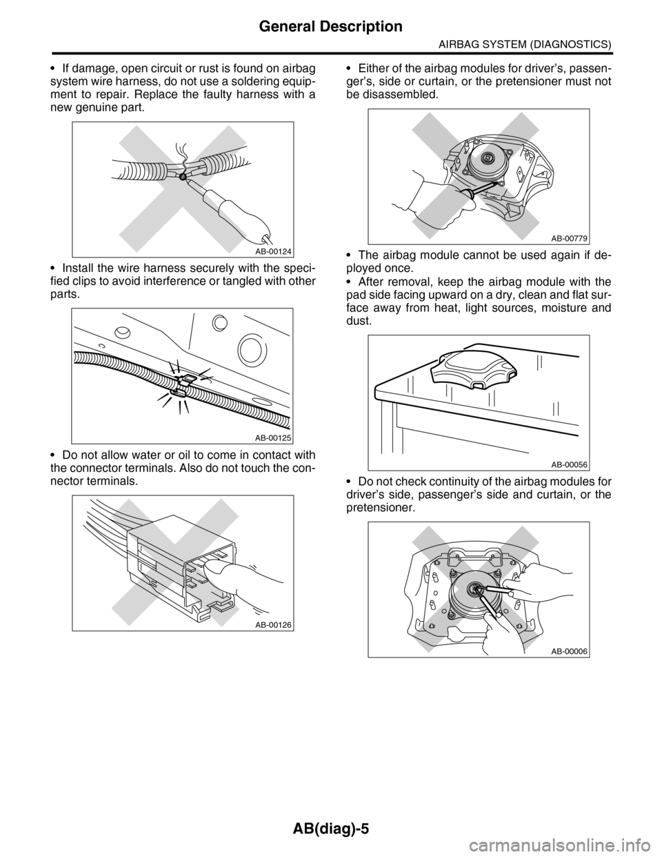
•If damage, open circuit or rust is found on airbag
system wire harness, do not use a soldering equip-
ment to repair. Replace the faulty harness with a
new genuine part.
•Install the wire harness securely with the speci-
fied clips to avoid interference or tangled with other
parts.
•Do not allow water or oil to come in contact with
the connector terminals. Also do not touch the con-
nector terminals.
•Either of the airbag modules for driver’s, passen-
ger’s, side or curtain, or the pretensioner must not
be disassembled.
•The airbag module cannot be used again if de-
ployed once.
•After removal, keep the airbag module with the
pad side facing upward on a dry, clean and flat sur-
face away from heat, light sources, moisture and
dust.
•Do not check continuity of the airbag modules for
driver’s side, passenger’s side and curtain, or the
pretensioner.
AB-00124
AB-00125
AB-00126
AB-00779
AB-00056
AB-00006
Page 189 of 2453
ET-3
Audio System
ENTERTAINMENT
2. Audio System
A: WIRING DIAGRAM
B: INSPECTION
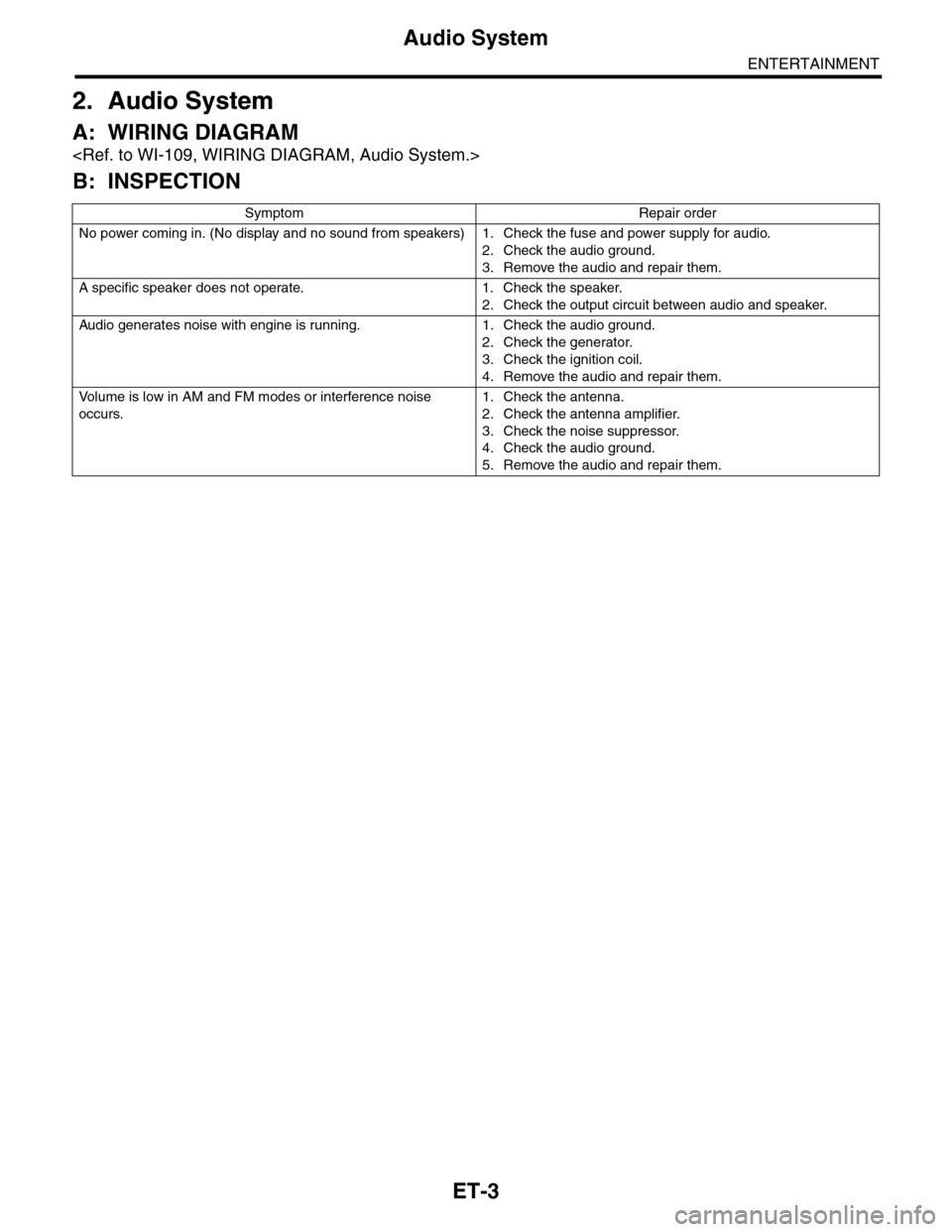
Symptom Repair order
No power coming in. (No display and no sound from speakers) 1. Check the fuse and power supply for audio.
2. Check the audio ground.
3. Remove the audio and repair them.
A specific speaker does not operate. 1. Check the speaker.
2. Check the output circuit between audio and speaker.
Audio generates noise with engine is r unning. 1. C heck the audio ground.
2. Check the generator.
3. Check the ignition coil.
4. Remove the audio and repair them.
Vo l u m e i s l o w i n A M a n d F M m o d e s o r i n t e r f e r e n c e n o i s e
occurs.
1. Check the antenna.
2. Check the antenna amplifier.
3. Check the noise suppressor.
4. Check the audio ground.
5. Remove the audio and repair them.
Page 204 of 2453
ET-19
Antenna
ENTERTAINMENT
14.Antenna
A: INSPECTION
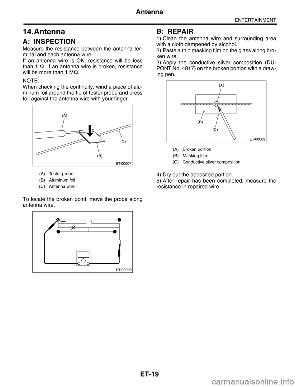
Measure the resistance between the antenna ter-
minal and each antenna wire.
If an antenna wire is OK, resistance will be less
than 1 Ω. If an antenna wire is broken, resistance
will be more than 1 MΩ.
NOTE:
When checking the continuity, wind a piece of alu-
minum foil around the tip of tester probe and press
foil against the antenna wire with your finger.
To locate the broken point, move the probe along
antenna wire.
B: REPAIR
1) Clean the antenna wire and surrounding area
with a cloth dampened by alcohol.
2) Paste a thin masking film on the glass along bro-
ken wire.
3) Apply the conductive silver composition (DU-
PONT No. 4817) on the broken portion with a draw-
ing pen.
4) Dry out the deposited portion.
5) After repair has been completed, measure the
resistance in repaired wire.
(A) Tester probe
(B) Aluminum foil
(C) Antenna wire
ET-00007
(B)
(C)
(A)
ET-00008
(A) Broken portion
(B) Masking film
(C) Conductive silver composition
ET-00009
(B)
(C)
(A)
Page 225 of 2453
EB-6
General Description
EXTERIOR BODY PANELS
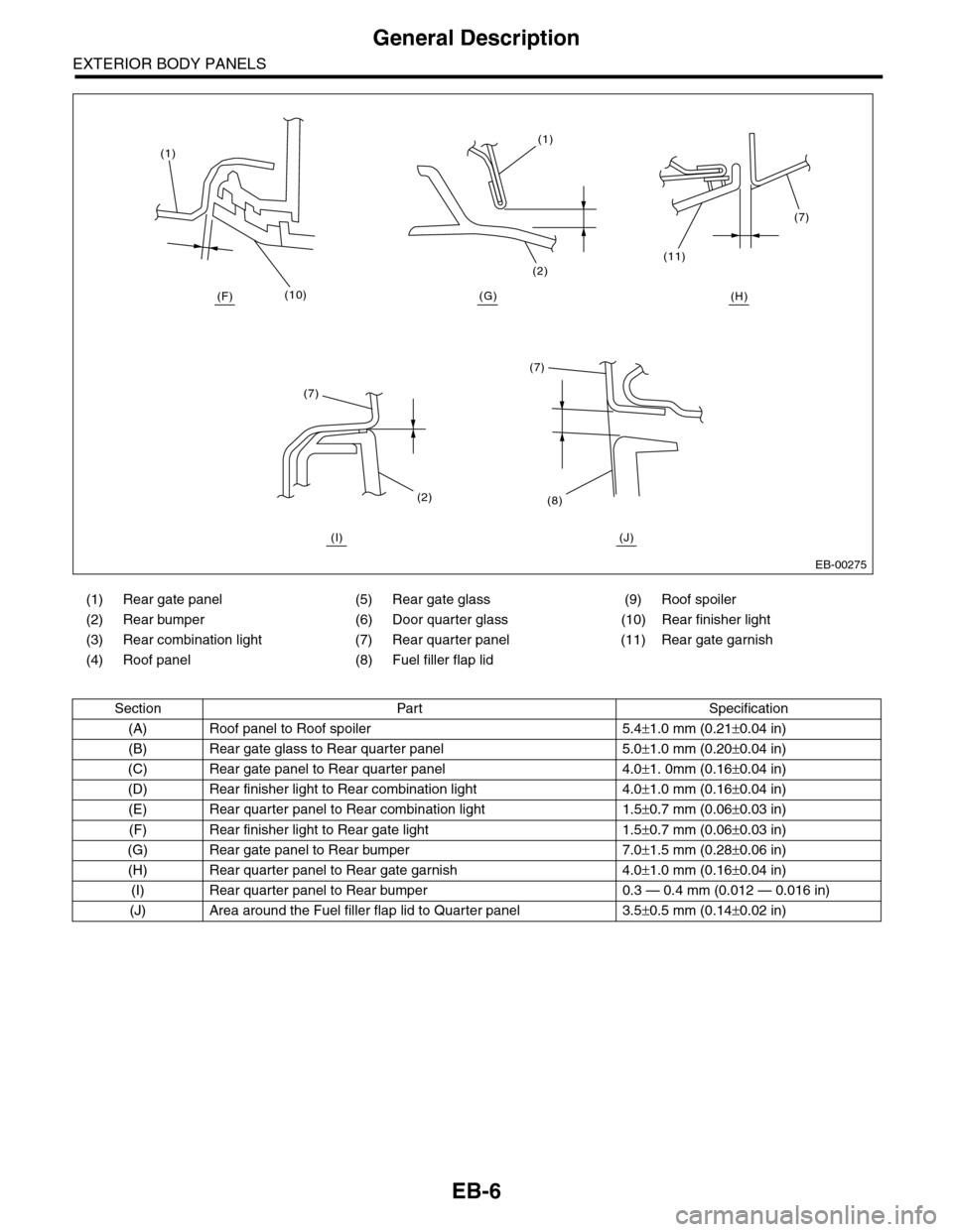
(1) Rear gate panel (5) Rear gate glass (9) Roof spoiler
(2) Rear bumper (6) Door quarter glass (10) Rear finisher light
(3) Rear combination light (7) Rear quarter panel (11) Rear gate garnish
(4) Roof panel (8) Fuel filler flap lid
Section Part Specification
(A) Roof panel to Roof spoiler 5.4±1.0 mm (0.21±0.04 in)
(B) Rear gate glass to Rear quarter panel 5.0±1.0 mm (0.20±0.04 in)
(C) Rear gate panel to Rear quarter panel 4.0±1. 0mm (0.16±0.04 in)
(D) Rear finisher light to Rear combination light 4.0±1.0 mm (0.16±0.04 in)
(E) Rear quarter panel to Rear combination light 1.5±0.7 mm (0.06±0.03 in)
(F) Rear finisher light to Rear gate light 1.5±0.7 mm (0.06±0.03 in)
(G) Rear gate panel to Rear bumper 7.0±1.5 mm (0.28±0.06 in)
(H) Rear quarter panel to Rear gate garnish 4.0±1.0 mm (0.16±0.04 in)
(I) Rear quarter panel to Rear bumper 0.3 — 0.4 mm (0.012 — 0.016 in)
(J) Area around the Fuel filler flap lid to Quarter panel 3.5±0.5 mm (0.14±0.02 in)
EB-00275
(10)
(1)(1)
(2)
(7)
(11)
(7)
(8)(2)
(7)
(H)(G)(F)
(I) (J)
Page 242 of 2453
EB-23
Rear Gate
EXTERIOR BODY PANELS
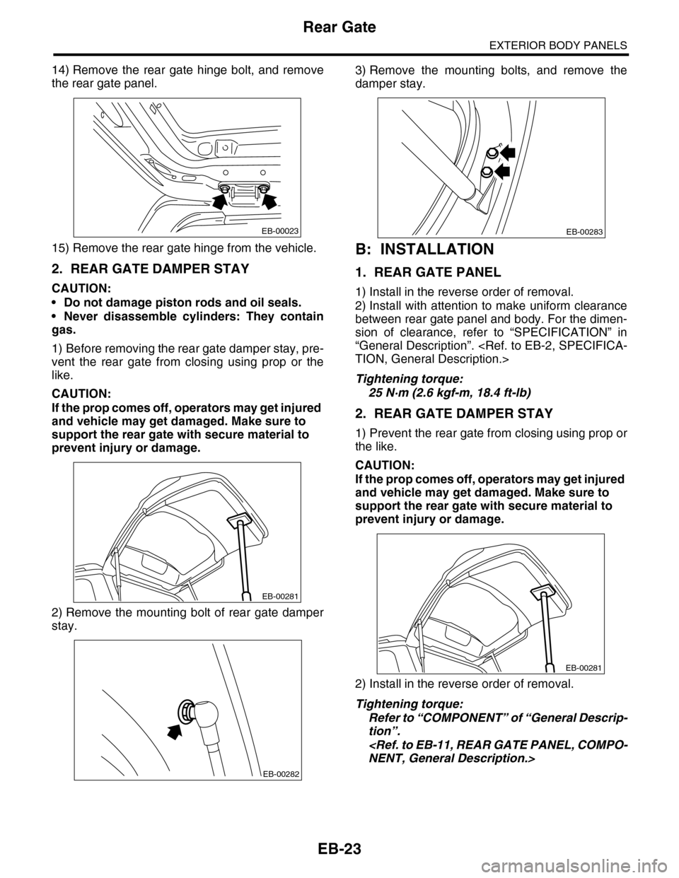
14) Remove the rear gate hinge bolt, and remove
the rear gate panel.
15) Remove the rear gate hinge from the vehicle.
2. REAR GATE DAMPER STAY
CAUTION:
•Do not damage piston rods and oil seals.
•Never disassemble cylinders: They contain
gas.
1) Before removing the rear gate damper stay, pre-
vent the rear gate from closing using prop or the
like.
CAUTION:
If the prop comes off, operators may get injured
and vehicle may get damaged. Make sure to
support the rear gate with secure material to
prevent injury or damage.
2) Remove the mounting bolt of rear gate damper
stay.
3) Remove the mounting bolts, and remove the
damper stay.
B: INSTALLATION
1. REAR GATE PANEL
1) Install in the reverse order of removal.
2) Install with attention to make uniform clearance
between rear gate panel and body. For the dimen-
sion of clearance, refer to “SPECIFICATION” in
“General Description”.
Tightening torque:
25 N·m (2.6 kgf-m, 18.4 ft-lb)
2. REAR GATE DAMPER STAY
1) Prevent the rear gate from closing using prop or
the like.
CAUTION:
If the prop comes off, operators may get injured
and vehicle may get damaged. Make sure to
support the rear gate with secure material to
prevent injury or damage.
2) Install in the reverse order of removal.
Tightening torque:
Refer to “COMPONENT” of “General Descrip-
tion”.
EB-00023
EB-00281
EB-00282
EB-00283
EB-00281
Page 265 of 2453
EI-23
Front Bumper
EXTERIOR/INTERIOR TRIM
C: REPAIR
1. COATING METHOD FOR PP BUMPER
Process
No.Process name Job contents
1Bumper installation
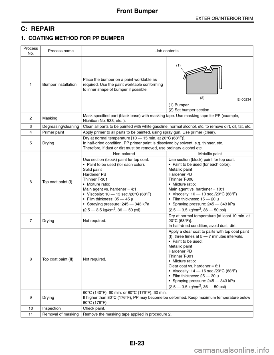
Place the bumper on a paint worktable as
required. Use the paint worktable conforming
to inner shape of bumper if possible.
(1) Bumper
(2) Set bumper section
2MaskingMask specified part (black base) with masking tape. Use masking tape for PP (example,
Nichiban No. 533, etc. ).
3Degreasing/cleaningClean all parts to be painted with white gasoline, normal alcohol, etc. to remove dirt, oil, fat, etc.
4Primer paint Apply primer to all parts to be painted, using spray gun. Use primer (clear).
5Drying
Dry at normal temperature [10 — 15 min. at 20°C (68°F)].
In half-dried condition, PP primer paint is dissolved by solvent, e.g. thinner, etc.
Therefore, if dust or dirt must be removed, use ordinary alcohol etc.
6Top coat paint (I)
Non-colored Metallic paint
Use section (block) paint for top coat.
•Paint to be used (for each color):
Solid paint
Hardener PB
Thinner T-301
•Mixture ratio:
Main agent vs. hardener = 4:1
• Viscosity: 10 — 13 sec./20°C (68°F)
•Film thickness: 35 — 45 µ
•Spraying pressure: 245 — 343 kPa
(2.5 — 3.5 kg/cm2, 36 — 50 psi)
Use section (block) paint for top coat.
•Paint to be used (for each color):
Metallic paint
Hardener PB
Thinner T-306
•Mixture ratio:
Main agent vs. hardener = 10:1
•Viscosity: 10 — 13 sec./20°C (68°F)
•Film thickness: 15 — 20 µ
•Spraying pressure: 245 — 343 kPa
(2.5 — 3.5 kg/cm2, 36 — 50 psi)
7Drying Not required.
Dry at normal temperature [at least 10 min. at
20°C (68°F)].
In half-dried condition, avoid dust, dirt.
8Top coat paint (II)Not required.
Apply a clear coat to parts with top coat paint
(I), three times at 5 — 7 minutes intervals.
•Paint to be used:
Metallic paint
Hardener PB
Thinner T-301
•Mixture ratio:
Clear coat vs. hardener = 6:1
•Viscosity: 14 — 16 sec./20°C (68°F)
•Film thickness: 25 — 30 µ
•Spraying pressure: 245 — 343 kPa
(2.5 — 3.5 kg/cm2, 36 — 50 psi)
9Drying
60°C (140°F), 60 min. or 80°C (176°F), 30 min.
If higher than 80°C (176°F), PP may become be deformed. Keep maximum temperature below
80°C (176°F).
10 Inspection Check paint.
11 Removal of masking Remove the masking tape applied in procedure 2.
EI-00234(2)
(1)
Page 320 of 2453
GW-25
Rear Window Defogger
GLASS/WINDOWS/MIRRORS
17.Rear Window Defogger
A: INSPECTION
1. CHECK WITH SUBARU SELECT MONITOR
CAUTION:
Check that the rear window defogger timer is in initial setting or customize setting before performing
inspection.
2. HEAT WIRE INSPECTION
CAUTION:
Use a dry and soft cloth when wiping dirt off the
glass. Move the cloth along the heat wire to
avoid damaging it.
1) Turn the ignition switch to ON.
2) Turn the defogger switch to ON.
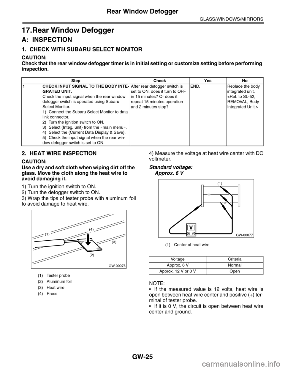
3) Wrap the tips of tester probe with aluminum foil
to avoid damage to heat wire.
4) Measure the voltage at heat wire center with DC
voltmeter.
Standard voltage:
Approx. 6 V
NOTE:
•If the measured value is 12 volts, heat wire is
open between heat wire center and positive (+) ter-
minal of tester probe.
•If it is 0 V, the circuit is open between heat wire
center and ground.
Step Check Yes No
1CHECK INPUT SIGNAL TO THE BODY INTE-
GRATED UNIT.
Check the input signal when the rear window
defogger switch is operated using Subaru
Select Monitor.
1) Connect the Subaru Select Monitor to data
link connector.
2) Turn the ignition switch to ON.
3) Select {Integ. unit} from the «main menu».
4) Select the {Current Data Display & Save}.
5) Check the input signal when the rear win-
dow defogger switch is set to ON.
After rear defogger switch is
set to ON, does it turn to OFF
in 15 minutes? Or does it
repeat 15 minutes operation
and 2 minutes stop?
END. Replace the body
integrated unit.
Integrated Unit.>
(1) Tester probe
(2) Aluminum foil
(3) Heat wire
(4) Press
GW-00076
(2)
(3)
(4)
(1)
(1) Center of heat wire
Vo l t a g e C r i t e r i a
Approx. 6 V Normal
Approx. 12 V or 0 V Open
GW-00077
(1)
Page 341 of 2453
AC-15
General Description
HVAC SYSTEM (HEATER, VENTILATOR AND A/C)
5. O-RING CONNECTIONS
•Always use a new O-ring.
•In order to keep the O-rings free of lint which can
cause a refrigerant gas leak, perform operations
without gloves and cloth.
•Apply compressor oil to O-rings to avoid sticking,
before installation.
•Use a torque wrench to tighten the O-ring fittings.
Over-tightening will cause damage to the O-ring
and cause tube end distortion.
•If the work is interrupted before completing pipe
connections, recap the tubes, components and fit-
tings with a plug or tape to prevent foreign matter
from entering.
•Visually check the surfaces and mating surfaces
of O-rings, threads and connecting points. If a fail-
ure is found, replace the applicable parts.
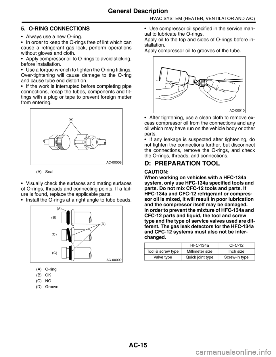
•Install the O-rings at a right angle to tube beads.
•Use compressor oil specified in the service man-
ual to lubricate the O-rings.
Apply oil to the top and sides of O-rings before in-
stallation.
Apply compressor oil to grooves of the tube.
•After tightening, use a clean cloth to remove ex-
cess compressor oil from the connections and any
oil which may have run on the vehicle body or other
parts.
•If any leakage is suspected after tightening, do
not tighten the connections further, but disconnect
the connections, remove the O-rings, and check
the O-rings, threads, and connections.
D: PREPARATION TOOL
CAUTION:
When working on vehicles with a HFC-134a
system, only use HFC-134a specified tools and
parts. Do not mix CFC-12 tools and parts. If
HFC-134a and CFC-12 refrigerant or compres-
sor oil is mixed, it will result in poor lubrication
and the compressor itself may be damaged.
In order to prevent the mixture of HFC-134a and
CFC-12 parts and liquid, the tool and screw
type and the type of service valves used are dif-
ferent. The gas leak detectors for the HFC-134a
and CFC-12 systems must also not be inter-
changed.
(A) Seal
(A) O-ring
(B) OK
(C) NG
(D) Groove
(A)
AC-00008
AC-00009
(D)
(B)
(C)
(C)
(A)
HFC-134aCFC-12
To o l & s c r e w t y p e M i l l i m e t e r s i z e I n c h s i z e
Va l ve t y p e Q u i ck j o i n t t y p e S c r ew - i n t y p e
AC-00010