sport mode SUBARU TRIBECA 2009 1.G Service Workshop Manual
[x] Cancel search | Manufacturer: SUBARU, Model Year: 2009, Model line: TRIBECA, Model: SUBARU TRIBECA 2009 1.GPages: 2453, PDF Size: 46.32 MB
Page 444 of 2453
IDI-5
Combination Meter System
INSTRUMENTATION/DRIVER INFO
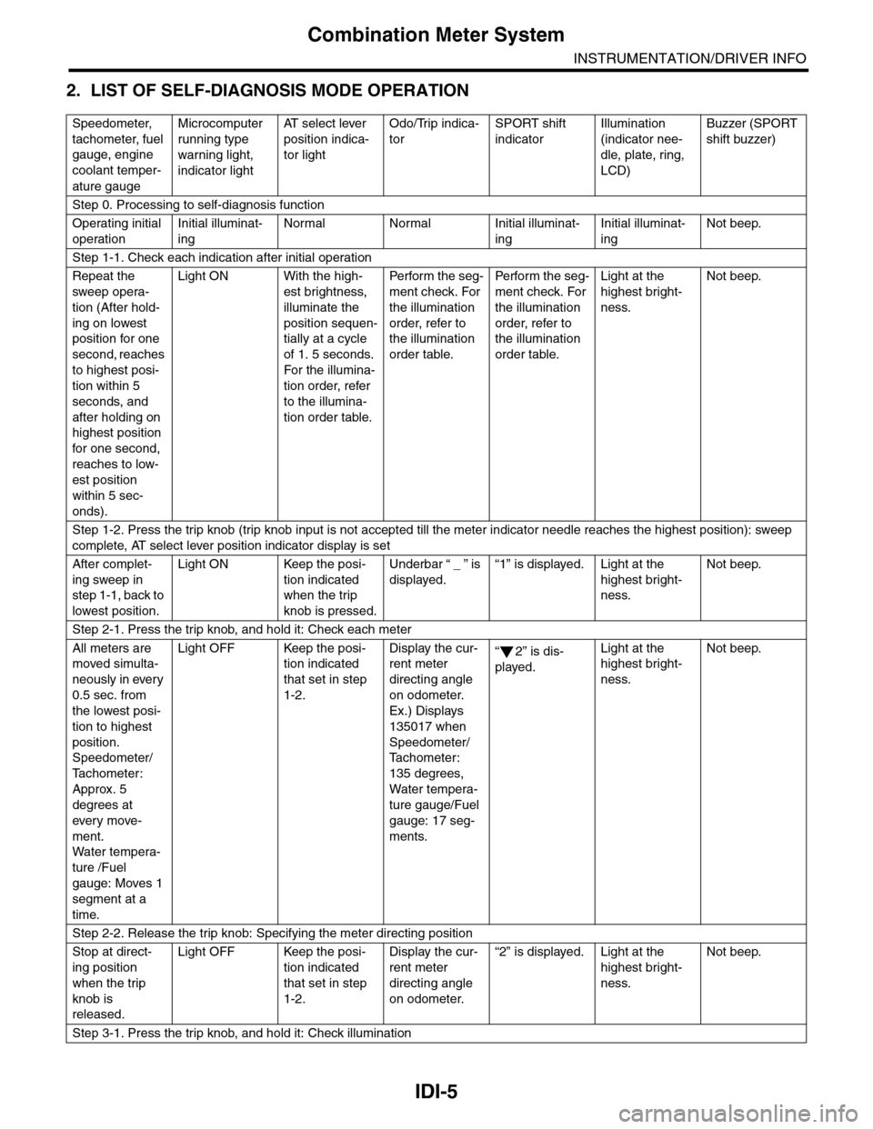
2. LIST OF SELF-DIAGNOSIS MODE OPERATION
Speedometer,
tachometer, fuel
gauge, engine
coolant temper-
ature gauge
Microcomputer
running type
warning light,
indicator light
AT s e l e c t l e v e r
position indica-
tor light
Odo/Trip indica-
tor
SPORT shift
indicator
Illumination
(indicator nee-
dle, plate, ring,
LCD)
Buzzer (SPORT
shift buzzer)
Step 0. Processing to self-diagnosis function
Operating initial
operation
Initial illuminat-
ing
Normal Normal Initial illuminat-
ing
Initial illuminat-
ing
Not beep.
Step 1-1. Check each indication after initial operation
Repeat the
sweep opera-
tion (After hold-
ing on lowest
position for one
second, reaches
to highest posi-
tion within 5
seconds, and
after holding on
highest position
for one second,
reaches to low-
est position
within 5 sec-
onds).
Light ON With the high-
est brightness,
illuminate the
position sequen-
tially at a cycle
of 1. 5 seconds.
For the illumina-
tion order, refer
to the illumina-
tion order table.
Pe r for m t he s eg -
ment check. For
the illumination
order, refer to
the illumination
order table.
Pe rfo r m t h e se g -
ment check. For
the illumination
order, refer to
the illumination
order table.
Light at the
highest bright-
ness.
Not beep.
Step 1-2. Press the trip knob (trip knob input is not accepted till the meter indicator needle reaches the highest position): sweep
complete, AT select lever position indicator display is set
After complet-
ing sweep in
step 1-1, back to
lowest position.
Light ON Keep the posi-
tion indicated
when the trip
knob is pressed.
Underbar “ _ ” is
displayed.
“1” is displayed. Light at the
highest bright-
ness.
Not beep.
Step 2-1. Press the trip knob, and hold it: Check each meter
All meters are
moved simulta-
neously in every
0.5 sec. from
the lowest posi-
tion to highest
position.
Speedometer/
Ta c h o m e t e r :
Approx. 5
degrees at
ever y move-
ment.
Wa t er t e mp er a-
ture /Fuel
gauge: Moves 1
segment at a
time.
Light OFF Keep the posi-
tion indicated
that set in step
1-2.
Display the cur-
rent meter
directing angle
on odometer.
Ex.) Displays
135017 when
Speedometer/
Ta c h o m e t e r :
135 degrees,
Water tempera-
ture gauge/Fuel
gauge: 17 seg-
ments.
“2” is dis-
played.
Light at the
highest bright-
ness.
Not beep.
Step 2-2. Release the trip knob: Specifying the meter directing position
Stop at direct-
ing position
when the trip
knob is
released.
Light OFF Keep the posi-
tion indicated
that set in step
1-2.
Display the cur-
rent meter
directing angle
on odometer.
“2” is displayed. Light at the
highest bright-
ness.
Not beep.
Step 3-1. Press the trip knob, and hold it: Check illumination
Page 445 of 2453
IDI-6
Combination Meter System
INSTRUMENTATION/DRIVER INFO
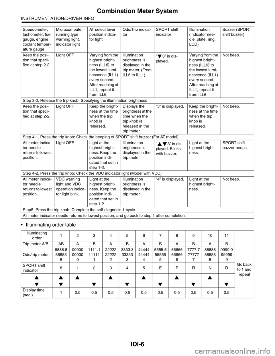
•Illuminating order table
Keep the posi-
tion that speci-
fied at step 2-2.
Light OFF Varying from the
highest bright-
ness (ILL6) to
the lowest lumi-
nescence (ILL1)
ever y second.
After reaching at
ILL1, repeat it
from ILL6.
Illumination
brightness is
displayed in the
trip meter. (From
ILL6 to ILL1)
“3” is dis-
played.
Va r y i n g f r o m t h e
highest bright-
ness (ILL6) to
the lowest lumi-
nescence (ILL1)
every second.
After reaching at
ILL1, repeat it
from ILL6.
Not beep.
Step 3-2. Release the trip knob: Specifying the illumination brightness
Keep the posi-
tion that speci-
fied at step 2-2.
Light OFF Keep the bright-
ness at the time
when the trip
knob is
released.
Displays the
brightness at the
time when the
trip knob is
released in the
trip meter.
“3” is displayed. Keep the bright-
ness at the time
when the trip
knob is
released.
Not beep.
Step 4-1. Press the trip knob: Check the beeping of SPORT shift buzzer (For AT model)
All meter indica-
tor needle
returns to lowest
position.
Light OFF Light at the
highest bright-
ness. Keep the
position indi-
cated that set in
step 1-2.
Illumination
brightness is
displayed in the
trip meter.
“8” is dis-
played. Blinks
with buzzer.
Light at the
highest bright-
ness.
SPORT shift
buzzer beeps.
Step 4-2. Press the trip knob: Check the VDC indicator light (Model with VDC)
All meter indica-
tor needle
returns to lowest
position.
VDC warning
light and VDC
operation indica-
tor light blink.
Light at the
highest bright-
ness. Keep the
position indi-
cated that set in
step 1-2.
Illumination
brightness is
displayed in the
trip meter.
“4” is displayed. Light at the
highest bright-
ness.
Not beep.
Step5. Press the trip knob: Complete the self-diagnosis 1 cycle
All meter indicator needle returns to lowest position, and go back to step 1 after completion.
Illuminating
order1234567891011
Tr i p m e t e r A / B A B A B A B A B A B A B
Go back
to 1 and
repeat
Odo/trip meter
8888.8
88888
8
00000
00000
0
1111.1
11111
1
22222
22222
2
3333.3
33333
3
44444
44444
4
5555.5
55555
5
66666
66666
6
7777.7
77777
7
88888
88888
8
9999.9
99999
9
SPORT shift
indicator812345EPRND
Display time
(sec.)10.50.50.50.50.50.50.50.50.50.5
Speedometer,
tachometer, fuel
gauge, engine
coolant temper-
ature gauge
Microcomputer
running type
warning light,
indicator light
AT s e l e c t l e v e r
position indica-
tor light
Odo/Trip indica-
tor
SPORT shift
indicator
Illumination
(indicator nee-
dle, plate, ring,
LCD)
Buzzer (SPORT
shift buzzer)
Page 469 of 2453
![SUBARU TRIBECA 2009 1.G Service Workshop Manual LAN(diag)-13
Subaru Select Monitor
LAN SYSTEM (DIAGNOSTICS)
2. READ CURRENT DATA
1) On the «Main Menu» display screen, select the {Each System Check} and press the [YES] key.
2) On the «System Sele SUBARU TRIBECA 2009 1.G Service Workshop Manual LAN(diag)-13
Subaru Select Monitor
LAN SYSTEM (DIAGNOSTICS)
2. READ CURRENT DATA
1) On the «Main Menu» display screen, select the {Each System Check} and press the [YES] key.
2) On the «System Sele](/img/17/7322/w960_7322-468.png)
LAN(diag)-13
Subaru Select Monitor
LAN SYSTEM (DIAGNOSTICS)
2. READ CURRENT DATA
1) On the «Main Menu» display screen, select the {Each System Check} and press the [YES] key.
2) On the «System Selection Menu» display screen, select the {Integ. Unit mode} and press the [YES] key.
3) On the «Integ. unit mode failure diag» display screen, select the {Current Data Display & Save} and press
the [YES] key.
4) On the «Current Data Display & Save» display screen, select the {12 Data Display} and press the [YES]
key.
5) Using the scroll key, scroll the display screen up or down until the desired data is shown.
•A support list contains both of analog and digital data, and they are shown in the following table.
3. DISPLAY OF ANALOG DATA
Items to be displayed Unit of measure Description Note
BATT Voltage (Control) 10 — 15 VBody integrated unit input
valueAlways
BATT Voltage (BACK UP) 10 — 15 VBody integrated unit input
valueAlways
IG power supply voltage 10 — 15 VBody integrated unit input
valueIgnition switch ON
ACC voltage 10 — 15 VBody integrated unit input
valueIgnition switch ACC
Illumination VR voltage 0 — 5 VBody integrated unit out-
put valueSmall light switch ON
Illumi. output d-ratio 0 — 100%Body integrated unit input
value
Small light ON
Illumination volume is other than bright.
Ambient temp sensor V 0 — 5 VBody integrated unit out-
put valueIgnition switch ON
Ambient temperature –40 — 87.5°CBody integrated unit out-
put valueIgnition switch ON
Fuel level voltage 0 — 8 VBody integrated unit input
valueIgnition switch ON
Fuel level resistance 0 — 102.3 ΩBody integrated unit input
valueIgnition switch ON
key-lock solenoid V 6 — 12 VBody integrated unit out-
put value
Other than parking range
Ignition ON
number of regist. 0 — 4 Key No. to register
Fr o nt W he e l S p ee d km / h C A N d a t a i np u t val u e R ec ep t io n f r o m V DC u ni t
VDC/ABS latest f-codeDTC display (Tempo-
rarily)CAN data input value
It is normal when DTC is not been input
even if this code is displayed.
Reception from VDC
Blower fan steps 0 — 2 levels CAN data input value0: OFF, 1: Low, 2: 2 levels or more
Reception from air conditioner ECM
Fuel level resistance2 0 — 102.3 ΩCAN data output value Reception from body integrated unit
Fuel consumption cc/s CAN data input valueReception from ECM and transmission to
center monitor
Coolant Temp. 40 — 130°C CAN data input value Reception from ECM
Ve h i c l e l a t e r a l Gm/s2CAN data input value Reception from VDC unit
SPORT Shift Stages 0 — 7 levels CAN data input value
(0: Light OFF; 1 — 5: Gear display; 6: Fail; 7:
AT F t e m p e r a t u r e H i g h / L o w )
Reception from TCM
Shift Position 0 — 7 levels CAN data input value
0: 1; 1: 2; 2: 3; 3: 4; 4: D; 5: N; 6: R; 7: P shift
position (There is no 8 input.)
Reception from TCM
Off delay timeOFF, Short, Normal,
Long
Body integrated unit set-
ting itemsCustomize setting
Auto lock time20, 30, 40, 50, 60 sec-
onds
Body integrated unit set-
ting itemsCustomize setting
Page 470 of 2453
LAN(diag)-14
Subaru Select Monitor
LAN SYSTEM (DIAGNOSTICS)
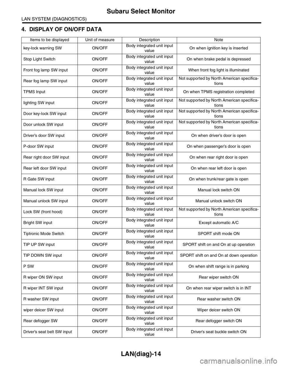
4. DISPLAY OF ON/OFF DATA
Items to be displayed Unit of measure Description Note
key-lock warning SW ON/OFFBody integrated unit input
valueOn when ignition key is inserted
Stop Light Switch ON/OFFBody integrated unit input
valueOn when brake pedal is depressed
Fr o nt fog la mp S W i n pu t O N/O FFBody integrated unit input
valueWhen front fog light is illuminated
Rear fog lamp SW input ON/OFFBody integrated unit input
value
Not supported by North American specifica-
tions
TPMS Input ON/OFFBody integrated unit input
valueOn when TPMS registration completed
lighting SW input ON/OFFBody integrated unit input
value
Not supported by North American specifica-
tions
Door key-lock SW input ON/OFFBody integrated unit input
value
Not supported by North American specifica-
tions
Door unlock SW input ON/OFFBody integrated unit input
value
Not supported by North American specifica-
tions
Driver’s door SW input ON/OFFBody integrated unit input
valueOn when driver’s door is open
P-door SW input ON/OFFBody integrated unit input
valueOn when passenger’s door is open
Rear right door SW input ON/OFFBody integrated unit input
valueOn when rear right door is open
Rear left door SW input ON/OFFBody integrated unit input
valueOn when rear left door is open
R Gate SW input ON/OFFBody integrated unit input
valueOn when trunk/rear gate is open
Manual lock SW input ON/OFFBody integrated unit input
valueManual lock switch ON
Manual unlock SW input ON/OFFBody integrated unit input
valueManual unlock switch ON
Lock SW (front hood) ON/OFFBody integrated unit input
value
Not supported by North American specifica-
tions
Bright SW input ON/OFFBody integrated unit input
valueExcept automatic A/C
Tiptronic Mode Switch ON/OFFBody integrated unit input
valueSPORT shift mode ON
TIP UP SW input ON/OFFBody integrated unit input
valueSPORT shift on and On at up operation
TIP DOWN SW input ON/OFFBody integrated unit input
valueSPORT shift on and On at down operation
P SW ON/OFFBody integrated unit input
valueOn when shift range is in parking
R wiper ON SW input ON/OFFBody integrated unit input
valueRear wiper switch ON
R wiper INT SW input ON/OFFBody integrated unit input
valueOn when rear wiper switch is in INT
R washer SW input ON/OFFBody integrated unit input
valueRear washer switch ON
wiper deicer SW input ON/OFFBody integrated unit input
valueWiper deicer switch ON
Rear defogger SW ON/OFFBody integrated unit input
valueRear defogger switch ON
Driver’s seat belt SW input ON/OFFBody integrated unit input
valueDriver’s seat buckle switch ON
Page 472 of 2453
LAN(diag)-16
Subaru Select Monitor
LAN SYSTEM (DIAGNOSTICS)
Immobilizer lamp output ON/OFFBody integrated unit output
valueOn when immobilizer pilot light blinks
Keyless operation 1 Registration/Nor malBody integrated unit input
value
Not supported by North American specifica-
tions
Keyless operation 2 Clear/Nor malBody integrated unit input
value
Not supported by North American specifica-
tions
CC Main Lamp On/Off CAN data input value
Cruise control switch on
Reception from ECM and transmission to
combination meter
CC Set Lamp On/Off CAN data input value
On when cruise control vehicle speed is set
Reception from ECM and transmission to
combination meter
SPORT Lamp On/Off CAN data input value
SPORT mode switch ON
Reception from TCM and transmission to
combination meter
SPORT Blink Blink/Off CAN data input value
TCM error signal reception ON
Reception from TCM and transmission to
combination meter
AT F Te m p e r a t u r e L a m p O n / O f f C A N d a t a i n p u t v a l u e
AT F o i l t e m p e r a t u r e r i s e O N
Reception from TCM and transmission to
combination meter
AT F B l i n k B l i n k / O f f C A N d a t a i n p u t v a l u eNot supported by North American specifica-
tions
Tire diameter abnormal 1 On/Off CAN data input valueNot supported by North American specifica-
tions
Tire diameter abnormal 2 Blink/Off CAN data input value
ON when difference in rotation between
front and rear wheels is 4% or more
Reception from TCM and transmission to
combination meter
SPORT Shift (UP) UP/OFFBody integrated unit input
valueON when shift lever can be operated up
SPORT Shift (DOWN) DOWN/OFFBody integrated unit input
valueON when shift lever can be operated down
SPORT Shift (buzzer 1) ON/OFF CAN data input valueReception from TCM and transmission to
combination meter
SPORT Shift (buzzer 2) ON/OFF CAN data input valueNot supported by North American specifica-
tions
ABS/VDC Judging ABS/VDC CAN data input valueTr a n s m i s s i o n f r o m v e h i c l e d y n a m i c c o n t r o l
(VDC) to high speed control module
ADA Existence Judging Yes/No CAN data input valueNot supported by North American specifica-
tions
Small light SW ON/OFFBody integrated unit input
valueOn when small light is illuminated
Headlight ON/OFFBody integrated unit output
value
Not supported by North American specifica-
tions
Headlight HI ON/OFFBody integrated unit output
value
Not supported by North American specifica-
tions
Tu r n s i g n a l L H O N / O F FBody integrated unit output
value
Not supported by North American specifica-
tions
Tu r n s i g n a l R H O N / O F FBody integrated unit output
value
Not supported by North American specifica-
tions
R defogger SW ON/OFFBody integrated unit output
valueRear defogger switch ON
Australia Judging Flag Australia/OthersBody integrated unit output
valueNorth American specifications have others
Large diameter tires Large diameter/othersBody integrated unit output
valueReception from combination meter
Items to be displayed Unit of measure Description Note
Page 2119 of 2453
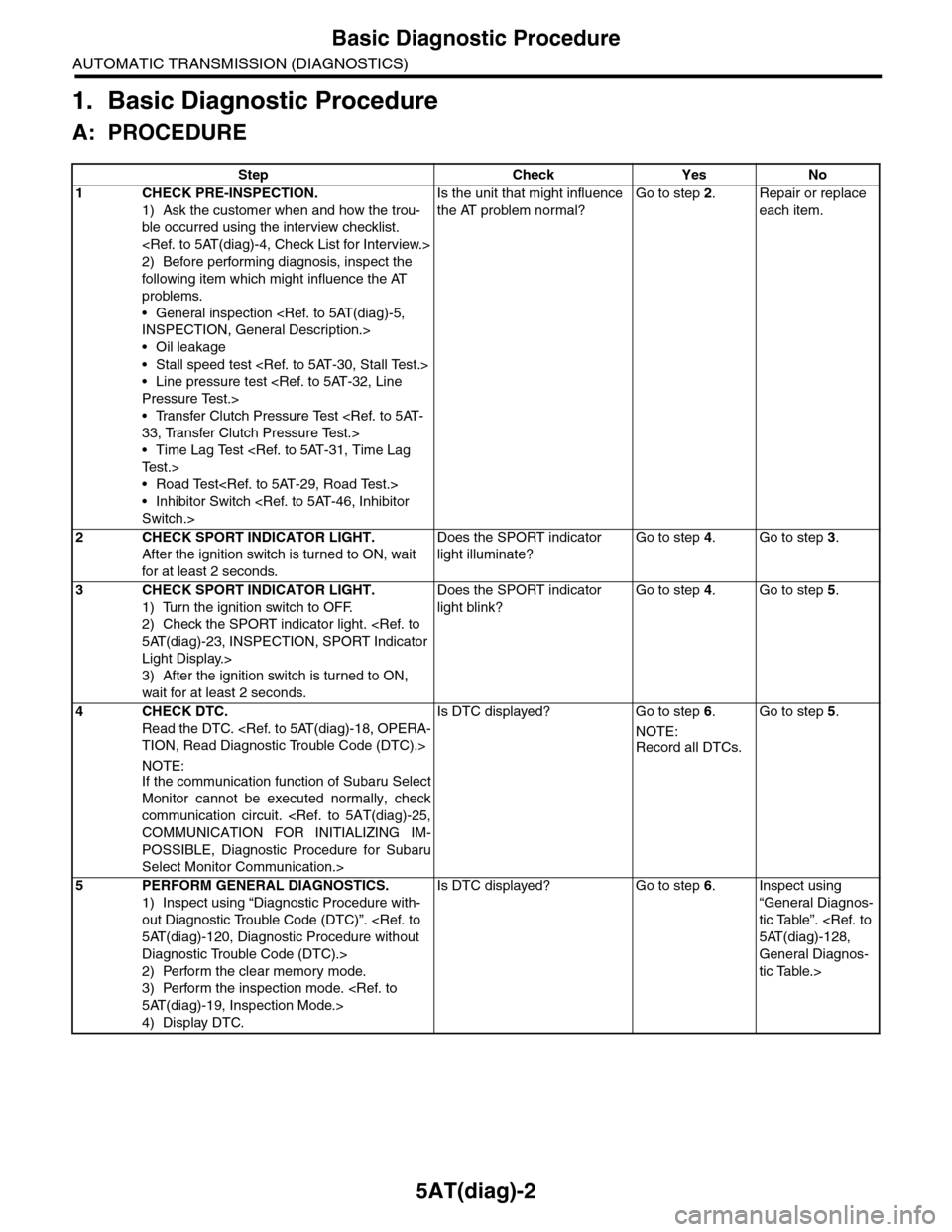
5AT(diag)-2
Basic Diagnostic Procedure
AUTOMATIC TRANSMISSION (DIAGNOSTICS)
1. Basic Diagnostic Procedure
A: PROCEDURE
Step Check Yes No
1CHECK PRE-INSPECTION.
1) Ask the customer when and how the trou-
ble occurred using the interview checklist.
2) Before performing diagnosis, inspect the
following item which might influence the AT
problems.
•General inspection
•Oil leakage
•Stall speed test
•Line pressure test
•Transfer Clutch Pressure Test
•Time Lag Test
•Road Test
•Inhibitor Switch
Is the unit that might influence
the AT problem normal?
Go to step 2.Repair or replace
each item.
2CHECK SPORT INDICATOR LIGHT.
After the ignition switch is turned to ON, wait
for at least 2 seconds.
Does the SPORT indicator
light illuminate?
Go to step 4.Go to step 3.
3CHECK SPORT INDICATOR LIGHT.
1) Turn the ignition switch to OFF.
2) Check the SPORT indicator light.
Light Display.>
3) After the ignition switch is turned to ON,
wait for at least 2 seconds.
Does the SPORT indicator
light blink?
Go to step 4.Go to step 5.
4CHECK DTC.
Read the DTC.
NOTE:If the communication function of Subaru Select
Monitor cannot be executed normally, check
communication circuit.
POSSIBLE, Diagnostic Procedure for Subaru
Select Monitor Communication.>
Is DTC displayed? Go to step 6.
NOTE:
Record all DTCs.
Go to step 5.
5PERFORM GENERAL DIAGNOSTICS.
1) Inspect using “Diagnostic Procedure with-
out Diagnostic Trouble Code (DTC)”.
Diagnostic Trouble Code (DTC).>
2) Perform the clear memory mode.
3) Perform the inspection mode.
4) Display DTC.
Is DTC displayed? Go to step 6.Inspect using
“General Diagnos-
tic Table”.
General Diagnos-
tic Table.>
Page 2147 of 2453
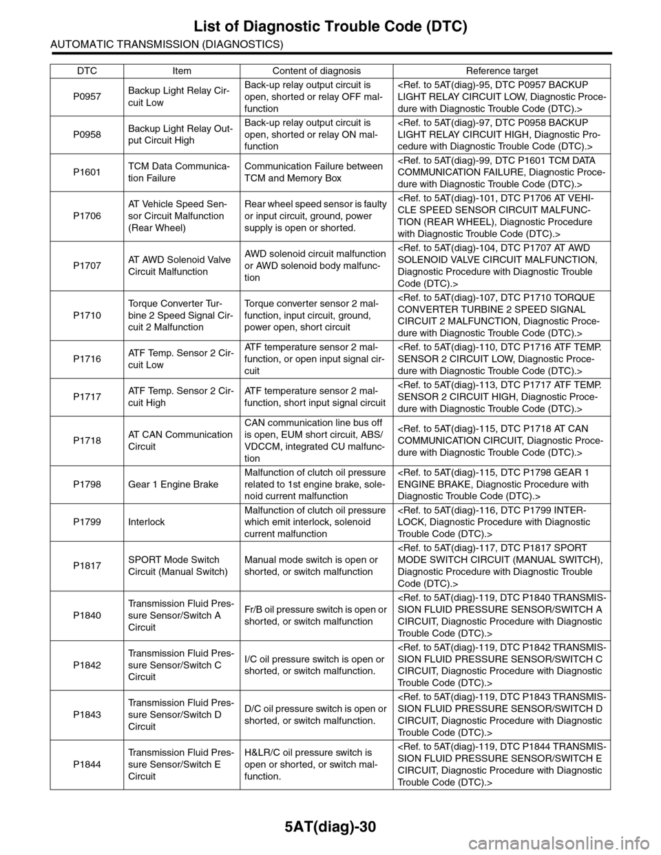
5AT(diag)-30
List of Diagnostic Trouble Code (DTC)
AUTOMATIC TRANSMISSION (DIAGNOSTICS)
P0957Backup Light Relay Cir-
cuit Low
Back-up relay output circuit is
open, shorted or relay OFF mal-
function
dure with Diagnostic Trouble Code (DTC).>
P0958Backup Light Relay Out-
put Circuit High
Back-up relay output circuit is
open, shorted or relay ON mal-
function
cedure with Diagnostic Trouble Code (DTC).>
P1601TCM Data Communica-
tion Failure
Communication Failure between
TCM and Memory Box
dure with Diagnostic Trouble Code (DTC).>
P1706
AT Ve h i c l e S p e e d S e n -
sor Circuit Malfunction
(Rear Wheel)
Rear wheel speed sensor is faulty
or input circuit, ground, power
supply is open or shorted.
TION (REAR WHEEL), Diagnostic Procedure
with Diagnostic Trouble Code (DTC).>
P1707AT A W D S o l e n o i d V a l v e
Circuit Malfunction
AWD solenoid circuit malfunction
or AWD solenoid body malfunc-
tion
Diagnostic Procedure with Diagnostic Trouble
Code (DTC).>
P1710
To r q u e C o n v e r t e r Tu r -
bine 2 Speed Signal Cir-
cuit 2 Malfunction
To r q u e c o n v e r t e r s e n s o r 2 m a l -
function, input circuit, ground,
power open, short circuit
CIRCUIT 2 MALFUNCTION, Diagnostic Proce-
dure with Diagnostic Trouble Code (DTC).>
P1716AT F Te m p . S e n s o r 2 C i r -
cuit Low
AT F t e m p e r a t u r e s e n s o r 2 m a l -
function, or open input signal cir-
cuit
dure with Diagnostic Trouble Code (DTC).>
P1717AT F Te m p . S e n s o r 2 C i r -
cuit High
AT F t e m p e r a t u r e s e n s o r 2 m a l -
function, short input signal circuit
dure with Diagnostic Trouble Code (DTC).>
P1718AT C A N C o m m u n i c a t i o n
Circuit
CAN communication line bus off
is open, EUM short circuit, ABS/
VDCCM, integrated CU malfunc-
tion
dure with Diagnostic Trouble Code (DTC).>
P1798 Gear 1 Engine Brake
Malfunction of clutch oil pressure
related to 1st engine brake, sole-
noid current malfunction
Diagnostic Trouble Code (DTC).>
P1799 Interlock
Malfunction of clutch oil pressure
which emit interlock, solenoid
current malfunction
Tr o u b l e C o d e ( D T C ) . >
P1817SPORT Mode Switch
Circuit (Manual Switch)
Manual mode switch is open or
shorted, or switch malfunction
Diagnostic Procedure with Diagnostic Trouble
Code (DTC).>
P1840
Tr a n s m i s s i o n F l u i d P r e s -
sure Sensor/Switch A
Circuit
Fr/B oil pressure switch is open or
shorted, or switch malfunction
CIRCUIT, Diagnostic Procedure with Diagnostic
Tr o u b l e C o d e ( D T C ) . >
P1842
Tr a n s m i s s i o n F l u i d P r e s -
sure Sensor/Switch C
Circuit
I/C oil pressure switch is open or
shorted, or switch malfunction.
CIRCUIT, Diagnostic Procedure with Diagnostic
Tr o u b l e C o d e ( D T C ) . >
P1843
Tr a n s m i s s i o n F l u i d P r e s -
sure Sensor/Switch D
Circuit
D/C oil pressure switch is open or
shorted, or switch malfunction.
CIRCUIT, Diagnostic Procedure with Diagnostic
Tr o u b l e C o d e ( D T C ) . >
P1844
Tr a n s m i s s i o n F l u i d P r e s -
sure Sensor/Switch E
Circuit
H&LR/C oil pressure switch is
open or shorted, or switch mal-
function.
CIRCUIT, Diagnostic Procedure with Diagnostic
Tr o u b l e C o d e ( D T C ) . >
DTC Item Content of diagnosis Reference target
Page 2160 of 2453
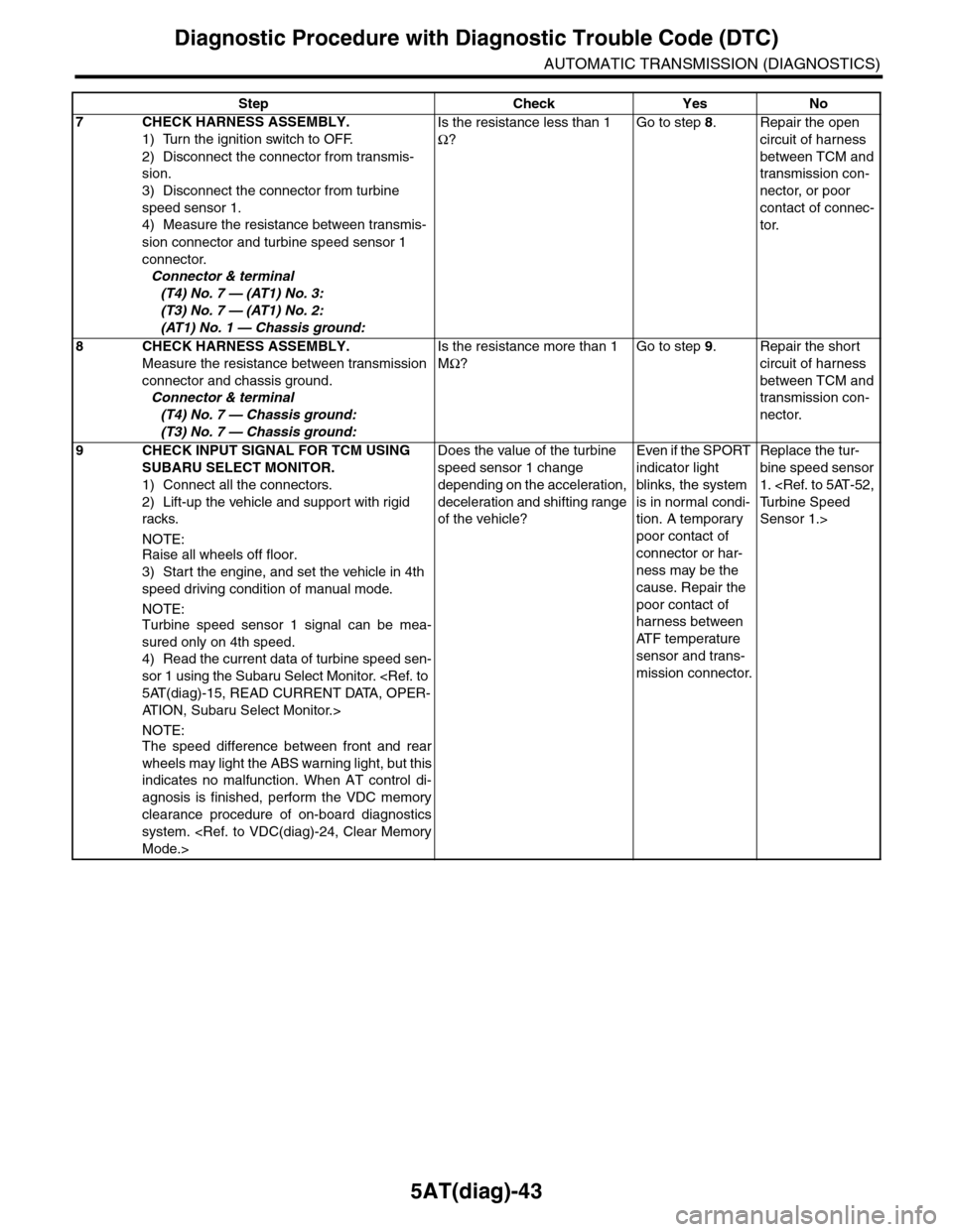
5AT(diag)-43
Diagnostic Procedure with Diagnostic Trouble Code (DTC)
AUTOMATIC TRANSMISSION (DIAGNOSTICS)
7CHECK HARNESS ASSEMBLY.
1) Turn the ignition switch to OFF.
2) Disconnect the connector from transmis-
sion.
3) Disconnect the connector from turbine
speed sensor 1.
4) Measure the resistance between transmis-
sion connector and turbine speed sensor 1
connector.
Connector & terminal
(T4) No. 7 — (AT1) No. 3:
(T3) No. 7 — (AT1) No. 2:
(AT1) No. 1 — Chassis ground:
Is the resistance less than 1
Ω?
Go to step 8.Repair the open
circuit of harness
between TCM and
transmission con-
nector, or poor
contact of connec-
tor.
8CHECK HARNESS ASSEMBLY.
Measure the resistance between transmission
connector and chassis ground.
Connector & terminal
(T4) No. 7 — Chassis ground:
(T3) No. 7 — Chassis ground:
Is the resistance more than 1
MΩ?
Go to step 9.Repair the short
circuit of harness
between TCM and
transmission con-
nector.
9CHECK INPUT SIGNAL FOR TCM USING
SUBARU SELECT MONITOR.
1) Connect all the connectors.
2) Lift-up the vehicle and support with rigid
racks.
NOTE:Raise all wheels off floor.
3) Start the engine, and set the vehicle in 4th
speed driving condition of manual mode.
NOTE:Turbine speed sensor 1 signal can be mea-
sured only on 4th speed.
4) Read the current data of turbine speed sen-
sor 1 using the Subaru Select Monitor.
AT I O N , S u b a r u S e l e c t M o n i t o r . >
NOTE:The speed difference between front and rear
wheels may light the ABS warning light, but this
indicates no malfunction. When AT control di-
agnosis is finished, perform the VDC memory
clearance procedure of on-board diagnostics
system.
Does the value of the turbine
speed sensor 1 change
depending on the acceleration,
deceleration and shifting range
of the vehicle?
Even if the SPORT
indicator light
blinks, the system
is in normal condi-
tion. A temporary
poor contact of
connector or har-
ness may be the
cause. Repair the
poor contact of
harness between
AT F t e m p e r a t u r e
sensor and trans-
mission connector.
Replace the tur-
bine speed sensor
1.
Sensor 1.>
Step Check Yes No
Page 2161 of 2453
5AT(diag)-44
Diagnostic Procedure with Diagnostic Trouble Code (DTC)
AUTOMATIC TRANSMISSION (DIAGNOSTICS)
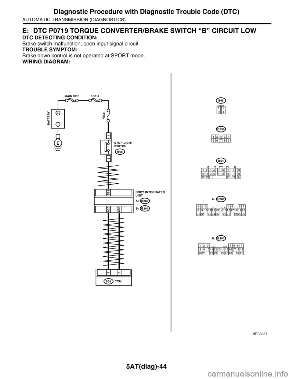
E: DTC P0719 TORQUE CONVERTER/BRAKE SWITCH “B” CIRCUIT LOW
DTC DETECTING CONDITION:
Brake switch malfunction, open input signal circuit
TROUBLE SYMPTOM:
Brake down control is not operated at SPORT mode.
WIRING DIAGRAM:
AT-03287
STOP LIGHTSWITCH
B65
BODY INTEGRATEDUNIT
B280A:
B281B:
B23
A20A30
B159
213489765
2
1
43
TCMB54
BATTERY
MAIN SBF SBF-2
NO.8
E
87654321
212220191615141312111091718282726252423
B281B:
87654321
2223212019161514131211109173018292827262524
B280A:
B54
12789563410 11 1219 20 2113 14 15 16 17 18222324
B65
1234
Page 2165 of 2453
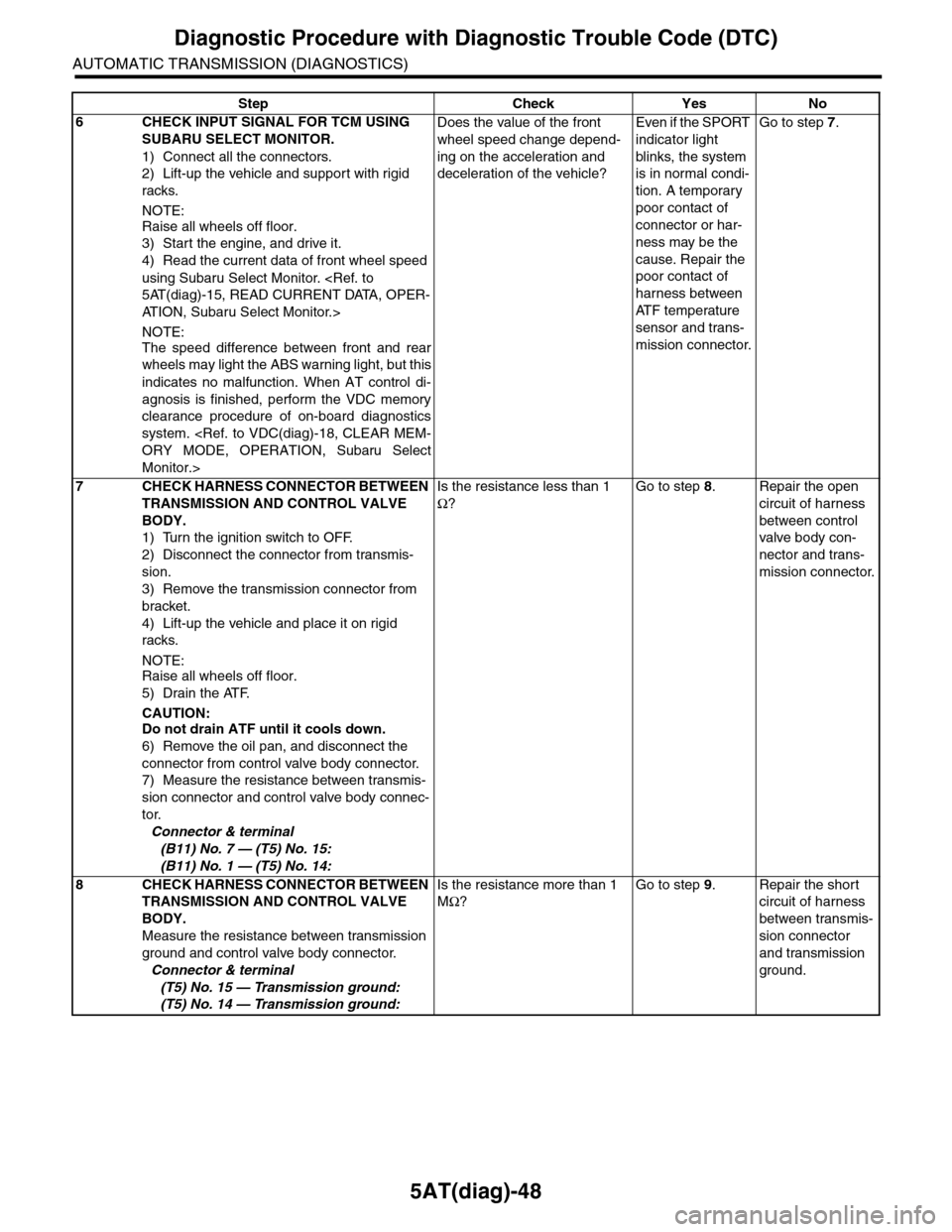
5AT(diag)-48
Diagnostic Procedure with Diagnostic Trouble Code (DTC)
AUTOMATIC TRANSMISSION (DIAGNOSTICS)
6CHECK INPUT SIGNAL FOR TCM USING
SUBARU SELECT MONITOR.
1) Connect all the connectors.
2) Lift-up the vehicle and support with rigid
racks.
NOTE:
Raise all wheels off floor.
3) Start the engine, and drive it.
4) Read the current data of front wheel speed
using Subaru Select Monitor.
AT I O N , S u b a r u S e l e c t M o n i t o r . >
NOTE:
The speed difference between front and rear
wheels may light the ABS warning light, but this
indicates no malfunction. When AT control di-
agnosis is finished, perform the VDC memory
clearance procedure of on-board diagnostics
system.
Monitor.>
Does the value of the front
wheel speed change depend-
ing on the acceleration and
deceleration of the vehicle?
Even if the SPORT
indicator light
blinks, the system
is in normal condi-
tion. A temporary
poor contact of
connector or har-
ness may be the
cause. Repair the
poor contact of
harness between
AT F t e m p e r a t u r e
sensor and trans-
mission connector.
Go to step 7.
7CHECK HARNESS CONNECTOR BETWEEN
TRANSMISSION AND CONTROL VALVE
BODY.
1) Turn the ignition switch to OFF.
2) Disconnect the connector from transmis-
sion.
3) Remove the transmission connector from
bracket.
4) Lift-up the vehicle and place it on rigid
racks.
NOTE:Raise all wheels off floor.
5) Drain the ATF.
CAUTION:Do not drain ATF until it cools down.
6) Remove the oil pan, and disconnect the
connector from control valve body connector.
7) Measure the resistance between transmis-
sion connector and control valve body connec-
tor.
Connector & terminal
(B11) No. 7 — (T5) No. 15:
(B11) No. 1 — (T5) No. 14:
Is the resistance less than 1
Ω?
Go to step 8.Repair the open
circuit of harness
between control
valve body con-
nector and trans-
mission connector.
8CHECK HARNESS CONNECTOR BETWEEN
TRANSMISSION AND CONTROL VALVE
BODY.
Measure the resistance between transmission
ground and control valve body connector.
Connector & terminal
(T5) No. 15 — Transmission ground:
(T5) No. 14 — Transmission ground:
Is the resistance more than 1
MΩ?
Go to step 9.Repair the short
circuit of harness
between transmis-
sion connector
and transmission
ground.
Step Check Yes No