p0500 SUBARU TRIBECA 2009 1.G Service Workshop Manual
[x] Cancel search | Manufacturer: SUBARU, Model Year: 2009, Model line: TRIBECA, Model: SUBARU TRIBECA 2009 1.GPages: 2453, PDF Size: 46.32 MB
Page 1197 of 2453
EN(H6DO)(diag)-36
Inspection Mode
ENGINE (DIAGNOSTICS)
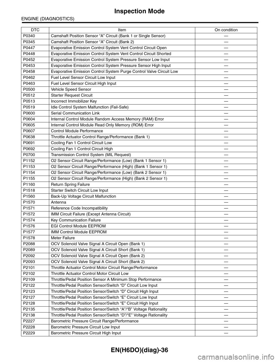
P0340 Camshaft Position Sensor “A” Circuit (Bank 1 or Single Sensor) —
P0345 Camshaft Position Sensor “A” Circuit (Bank 2) —
P0447 Evaporative Emission Control System Vent Control Circuit Open —
P0448 Evaporative Emission Control System Vent Control Circuit Shorted —
P0452 Evaporative Emission Control System Pressure Sensor Low Input —
P0453 Evaporative Emission Control System Pressure Sensor High Input —
P0458 Evaporative Emission Control System Purge Control Valve Circuit Low —
P0462 Fuel Level Sensor Circuit Low Input —
P0463 Fuel Level Sensor Circuit High Input —
P0500 Vehicle Speed Sensor—
P0512 Starter Request Circuit—
P0513 Incorrect Immobilizer Key —
P0519 Idle Control System Malfunction (Fail-Safe) —
P0600 Serial Communication Link —
P0604 Internal Control Module Random Access Memory (RAM) Error —
P0605 Internal Control Module Read Only Memory (ROM) Error —
P0607 Control Module Performance —
P0638 Throttle Actuator Control Range/Performance (Bank 1) —
P0691 Cooling Fan 1 Control Circuit Low —
P0692 Cooling Fan 1 Control Circuit High —
P0700 Transmission Control System (MIL Request) —
P1152 O2 Sensor Circuit Range/Performance (Low) (Bank 1 Sensor 1) —
P1153 O2 Sensor Circuit Range/Performance (High) (Bank 1 Sensor 1) —
P1154 O2 Sensor Circuit Range/Performance (Low) (Bank 2 Sensor 1) —
P1155 O2 Sensor Circuit Range/Performance (High) (Bank 2 Sensor 1) —
P1160 Return Spring Failure—
P1518 Starter Switch Circuit Low Input —
P1560 Back-Up Voltage Circuit Malfunction —
P1570 Antenna—
P1571 Reference Code Incompatibility —
P1572 IMM Circuit Failure (Except Antenna Circuit) —
P1574 Key Communication Failure —
P1576 EGI Control Module EEPROM —
P1577 IMM Control Module EEPROM —
P1578 Meter Failure—
P2088 OCV Solenoid Valve Signal A Circuit Open (Bank 1) —
P2089 OCV Solenoid Valve Signal A Circuit Short (Bank 1) —
P2092 OCV Solenoid Valve Signal A Circuit Open (Bank 2) —
P2093 OCV Solenoid Valve Signal A Circuit Short (Bank 2) —
P2101 Throttle Actuator Control Motor Circuit Range/Performance —
P2102 Throttle Actuator Control Motor Circuit Low —
P2109 Throttle/Pedal Position Sensor A Minimum Stop Performance —
P2122 Throttle/Pedal Position Sensor/Switch “D” Circuit Low Input —
P2123 Throttle/Pedal Position Sensor/Switch “D” Circuit High Input —
P2127 Throttle/Pedal Position Sensor/Switch “E” Circuit Low Input —
P2128 Throttle/Pedal Position Sensor/Switch “E” Circuit High Input —
P2135 Throttle/Pedal Position Sensor/Switch “A”/“B” Voltage Rationality —
P2138 Throttle/Pedal Position Sensor/Switch “D”/“E” Voltage Rationality —
P2227 Barometric Pressure Circuit Range/Performance —
P2228 Barometric Pressure Circuit Low Input —
P2229 Barometric Pressure Circuit High Input —
DTC Item On condition
Page 1234 of 2453
EN(H6DO)(diag)-73
List of Diagnostic Trouble Code (DTC)
ENGINE (DIAGNOSTICS)
P0345 Camshaft Position Sensor “A” Circuit
(Bank 2)
Code (DTC).>
P0420 Catalyst System Efficiency Below
Threshold (Bank 1)
nostic Trouble Code (DTC).>
P0442 Evaporative Emission Control Sys-
tem Leak Detected (Small Leak)
dure with Diagnostic Trouble Code (DTC).>
P0447 Evaporative Emission Control Sys-
tem Vent Control Circuit Open
dure with Diagnostic Trouble Code (DTC).>
P0448 Evaporative Emission Control Sys-
tem Vent Control Circuit Shorted
Procedure with Diagnostic Trouble Code (DTC).>
P0451 Evaporative Emission Control Sys-
tem Pressure Sensor
Diagnostic Trouble Code (DTC).>
P0452 Evaporative Emission Control Sys-
tem Pressure Sensor Low Input
dure with Diagnostic Trouble Code (DTC).>
P0453 Evaporative Emission Control Sys-
tem Pressure Sensor High Input
dure with Diagnostic Trouble Code (DTC).>
P0456 Evaporative Emission Control Sys-
tem Leak Detected (Very Small
Leak)
Procedure with Diagnostic Trouble Code (DTC).>
P0457 Evaporative Emission Control Sys-
tem Leak Detected (Fuel Cap Loose/
Off)
nostic Procedure with Diagnostic Trouble Code (DTC).>
P0458 Evaporative Emission Control Sys-
tem Purge Control Valve Circuit Low
Procedure with Diagnostic Trouble Code (DTC).>
P0459 Evaporative Emission Control Sys-
tem Purge Control Valve Circuit High
Procedure with Diagnostic Trouble Code (DTC).>
P0461 Fuel Level Sensor Circuit Range/Per-
for mance
ble Code (DTC).>
P0462 Fuel Level Sensor Circuit Low Input
(DTC).>
P0463 Fuel Level Sensor Circuit High Input
(DTC).>
P0464 Fuel Level Sensor Circuit Intermittent
(DTC).>
P0483 Cooling Fan Rationality Check
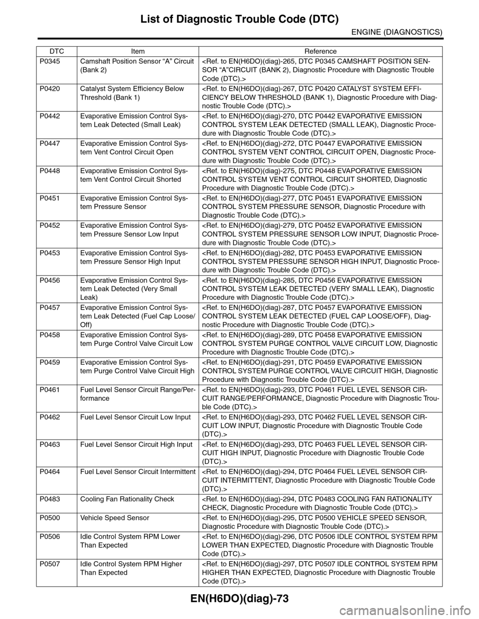
P0500 Vehicle Speed Sensor
P0506 Idle Control System RPM Lower
Than Expected
Code (DTC).>
P0507 Idle Control System RPM Higher
Than Expected
Code (DTC).>
DTC Item Reference
Page 1456 of 2453
EN(H6DO)(diag)-295
Diagnostic Procedure with Diagnostic Trouble Code (DTC)
ENGINE (DIAGNOSTICS)
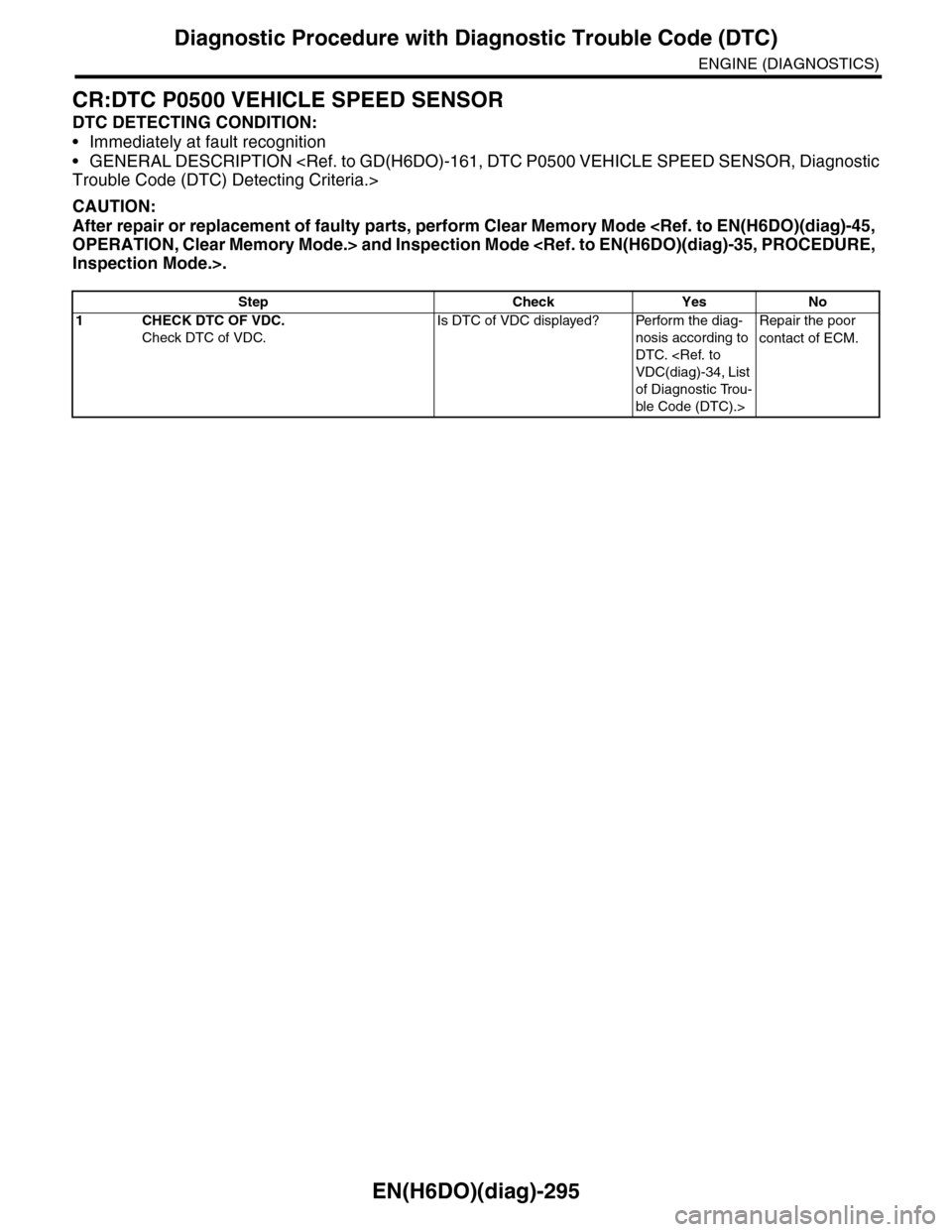
CR:DTC P0500 VEHICLE SPEED SENSOR
DTC DETECTING CONDITION:
•Immediately at fault recognition
•GENERAL DESCRIPTION
CAUTION:
After repair or replacement of faulty parts, perform Clear Memory Mode
Step Check Yes No
1CHECK DTC OF VDC.
Check DTC of VDC.
Is DTC of VDC displayed? Perform the diag-
nosis according to
DTC.
of Diagnostic Trou-
ble Code (DTC).>
Repair the poor
contact of ECM.
Page 1618 of 2453
GD(H6DO)-6
List of Diagnostic Trouble Code (DTC)
GENERAL DESCRIPTION
P0457 Evaporative Emission Control Sys-
tem Leak Detected (Fuel Cap
Loose/Off)
Tr o u b l e C o d e ( D T C ) D e t e c t i n g C r i t e r i a . >
P0458 Evaporative Emission Control Sys-
tem Purge Control Valve Circuit
Low
ble Code (DTC) Detecting Criteria.>
P0459 Evaporative Emission Control Sys-
tem Purge Control Valve Circuit
High
Tr o u b l e C o d e ( D T C ) D e t e c t i n g C r i t e r i a . >
P0461 Fuel Level Sensor Circuit Range/
Per fo r m an ce
ria.>
P0462 Fuel Level Sensor Circuit Low
Input
P0463 Fuel Level Sensor Circuit High
Input
P0464 Fuel Level Sensor Circuit Intermit-
tent
P0483 Cooling Fan Rationality Check
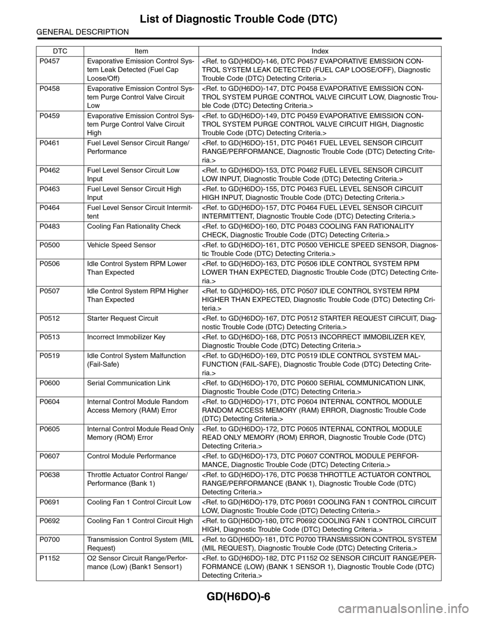
P0500 Vehicle Speed Sensor
P0506 Idle Control System RPM Lower
Than Expected
ria.>
P0507 Idle Control System RPM Higher
Than Expected
teria.>
P0512 Starter Request Circuit
P0513 Incorrect Immobilizer Key
P0519 Idle Control System Malfunction
(Fail-Safe)
ria.>
P0600 Serial Communication Link
P0604 Internal Control Module Random
Access Memory (RAM) Error
(DTC) Detecting Criteria.>
P0605 Internal Control Module Read Only
Memory (ROM) Error
Detecting Criteria.>
P0607 Control Module Performance
P0638 Throttle Actuator Control Range/
Per fo r m an ce ( B an k 1 )
Detecting Criteria.>
P0691 Cooling Fan 1 Control Circuit Low
P0692 Cooling Fan 1 Control Circuit High
P0700 Transmission Control System (MIL
Request)
P1152 O2 Sensor Circuit Range/Perfor-
mance (Low) (Bank1 Sensor1)
Detecting Criteria.>
DTC Item Index
Page 1773 of 2453
GD(H6DO)-161
Diagnostic Trouble Code (DTC) Detecting Criteria
GENERAL DESCRIPTION
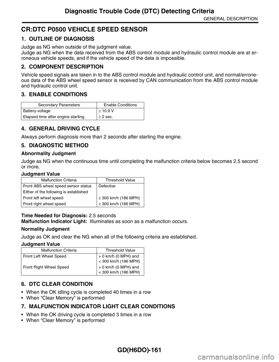
CR:DTC P0500 VEHICLE SPEED SENSOR
1. OUTLINE OF DIAGNOSIS
Judge as NG when outside of the judgment value.
Judge as NG when the data received from the ABS control module and hydraulic control module are at er-
roneous vehicle speeds, and if the vehicle speed of the data is impossible.
2. COMPONENT DESCRIPTION
Vehicle speed signals are taken in to the ABS control module and hydraulic control unit, and normal/errone-
ous data of the ABS wheel speed sensor is received by CAN communication from the ABS control module
and hydraulic control unit.
3. ENABLE CONDITIONS
4. GENERAL DRIVING CYCLE
Always perform diagnosis more than 2 seconds after starting the engine.
5. DIAGNOSTIC METHOD
Abnormality Judgment
Judge as NG when the continuous time until completing the malfunction criteria below becomes 2.5 second
or more.
Time Needed for Diagnosis: 2.5 seconds
Malfunction Indicator Light: Illuminates as soon as a malfunction occurs.
Normality Judgment
Judge as OK and clear the NG when all of the following criteria are established.
6. DTC CLEAR CONDITION
•When the OK idling cycle is completed 40 times in a row
•When “Clear Memory” is performed
7. MALFUNCTION INDICATOR LIGHT CLEAR CONDITIONS
•When the OK driving cycle is completed 3 times in a row
•When “Clear Memory” is performed
Secondary Parameters Enable Conditions
Battery voltage≥ 10.9 V
Elapsed time after engine starting≥ 2 sec.
Judgment Value
Malfunction Criteria Threshold Value
Fr o nt A B S w he e l s pe ed se n so r st at u s D efe ct i ve
Either of the following is established
Fr o nt l ef t whe e l s pe e d≥ 300 km/h (186 MPH)
Fr o nt r i gh t whe e l sp e ed≥ 300 km/h (186 MPH)
Judgment Value
Malfunction Criteria Threshold Value
Fr o nt L ef t Wh e el S pe e d > 0 km /h ( 0 M P H) a n d
< 300 km/h (186 MPH)
Fr o nt Ri gh t Wh e el S pe e d > 0 km /h ( 0 M P H) a n d
< 300 km/h (186 MPH)