horn SUBARU TRIBECA 2014 1.G User Guide
[x] Cancel search | Manufacturer: SUBARU, Model Year: 2014, Model line: TRIBECA, Model: SUBARU TRIBECA 2014 1.GPages: 426, PDF Size: 6.37 MB
Page 257 of 426
7-10Starting and operating
transmitter within a few seconds immedi-ately following remote engine start shut-down.
&Pre-heating or pre-cooling
the interior of the vehicle
Before exiting the vehicle, set the tem-perature controls to the desired settingand operation. After the system starts thevehicle, the heater or air-conditioning willactivate and heat or cool the interior toyour setting.
&Service mode
In service mode, the remote start functionis temporarily disabled to prevent thesystem from unexpectedly starting theengine while being serviced.
!To engage the service mode
Turn the ignition switch to the“ON”position, depress and hold the brake pedalthen, press and release the“”button onthe remote engine start transmitter threetimes. The system will pause for 1 secondand then flash the parking lights and honkthe hornthree times indicating that thesystem is in service mode. When attempt-ing to activate the remote start systemwhile in service mode, the parking lightswill flash and the horn will honk two timesand will not start.
!To disengage the service mode
Turn the ignition switch to the“ON”position, depress and hold the brakepedal, then press and release the“”button on the remote engine start trans-mitter three times. The system will pausefor 1 second and flash the parking lightsone time indicating that the system hasexited service mode.
NOTE
When taking your vehicle in for service,it is recommended that you inform theservice personnel that your vehicle isequippedwith a remote engine startsystem.
&Remote engine start trans-
mitter programming and pro-
grammable feature option
New transmitters can be programmed tothe remote engine start system in theevent that remote engine start transmittersare lost, stolen or damaged. The remoteengine start system also has one pro-grammable feature that can be adjustedfor user preference.
The remote engine start system can beprogrammed to either make an audiblehorn chirp upon remote start activation ornot. Remote engine start transmitter pro-gramming and feature programming can
be adjusted using the following procedure.
1. Open the driver’s door (the driver’sdoor must remain opened throughout theentire process).
2. Insert the key into the vehicle’s ignitionswitch and turn to the“ON”position.
3. Locate the small black programmingbutton behind the fuse box cover, on thedriver’s side left under the dashboardpanel.
4. Press and hold the black programmingbutton for 10 to 15 seconds. The horn willhonk and the parking lights will flash threetimes to indicate that the system hasentered programming mode. At this pointyou can perform either action (step 5 orstep 6).
5. To program a remote transmitter:press and release the“”button on eachtransmitter. The horn will honk and theparking lights will flash one time to indicatea successful transmitter learn each timethe“”button is pressed. You canprogram up to eight transmitters.
6. To toggle the Horn Confirmation chirpsON/OFF: press and release the brake totoggle the feature. The horn will chirp andthe parking lights will flash one time toindicate Confirmation Horn Chirps are“OFF”. The horn will honk and the parkinglights will flash 2 times to indicate Con-firmation Horn Chirps are“ON”. Depres-
Page 258 of 426
sing the brake pedal repeatedly will togglethe feature ON or OFF each time.
7. To exit the remote transmitter andfeature programming mode, turn the igni-tion switch to the“LOCK”position, removethe key from the ignition switch and testoperation of the remote transmitter(s) andhorn confirmation feature.
&System maintenance
!Changing the batteries
CAUTION
.Do not let dust, oil or water get onor in the remote engine starttransmitter when replacing thebattery.
.Be careful not to damage theprinted circuit board in the re-mote engine start transmitterwhen replacing the battery.
.Be careful not to allow children totouch the battery and any re-moved parts; children couldswallowthem.
.There is a danger of explosion ifan incorrect replacement batteryis used. Replace only with thesame or equivalent type of bat-tery.
.Batteries should not be exposedto excessive heat such as sun-shine, fire or the like.
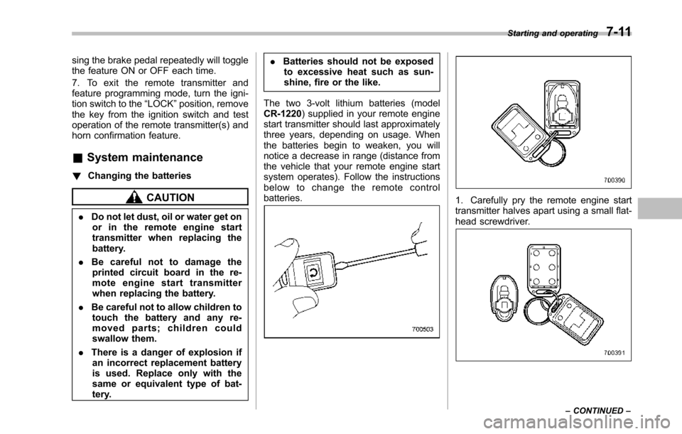
The two 3-volt lithium batteries (modelCR-1220) supplied in your remote enginestart transmitter should last approximatelythree years, depending on usage. Whenthebatteries begin to weaken, you willnotice a decrease in range (distance fromthe vehicle that your remote engine startsystem operates). Follow the instructionsbelow to change the remote controlbatteries.1. Carefully pry the remote engine starttransmitter halves apart using a small flat-head screwdriver.
Starting and operating7-11
–CONTINUED–
Page 388 of 426
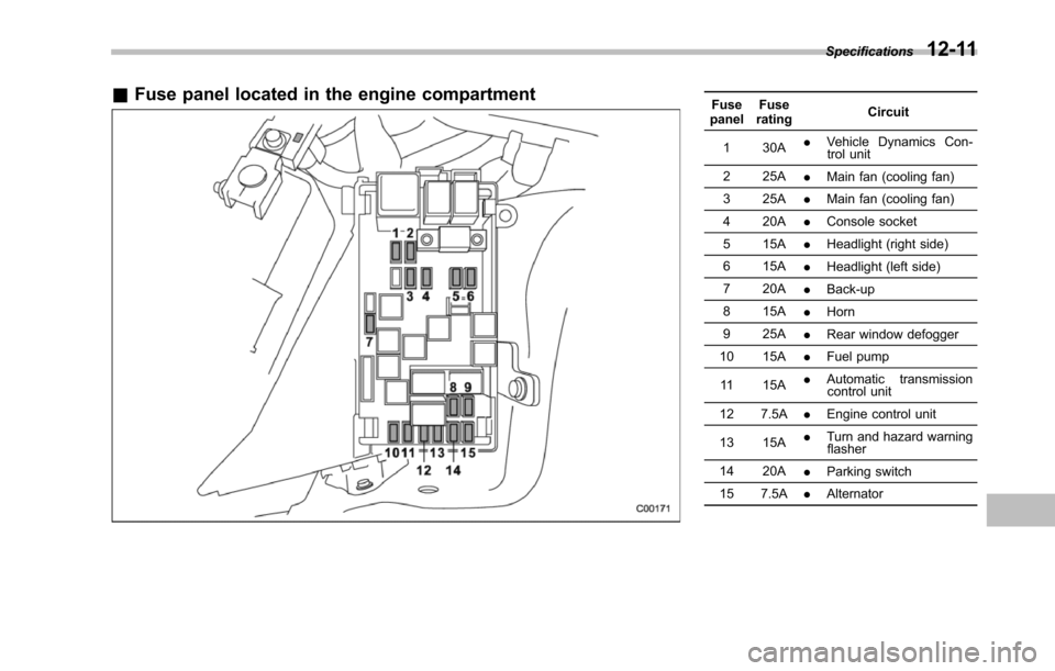
&Fuse panel located in the engine compartmentFusepanelFuseratingCircuit
1 30A.Vehicle Dynamics Con-trol unit
2 25A.Main fan (cooling fan)
3 25A.Main fan (cooling fan)
4 20A.Console socket
5 15A.Headlight (right side)
6 15A.Headlight (left side)
7 20A.Back-up
8 15A.Horn
9 25A.Rear window defogger
10 15A.Fuel pump
11 15A.Automatic transmissioncontrol unit
12 7.5A.Engine control unit
13 15A.Turn and hazard warningflasher
14 20A.Parking switch
15 7.5A.Alternator
Specifications12-11
Page 414 of 426
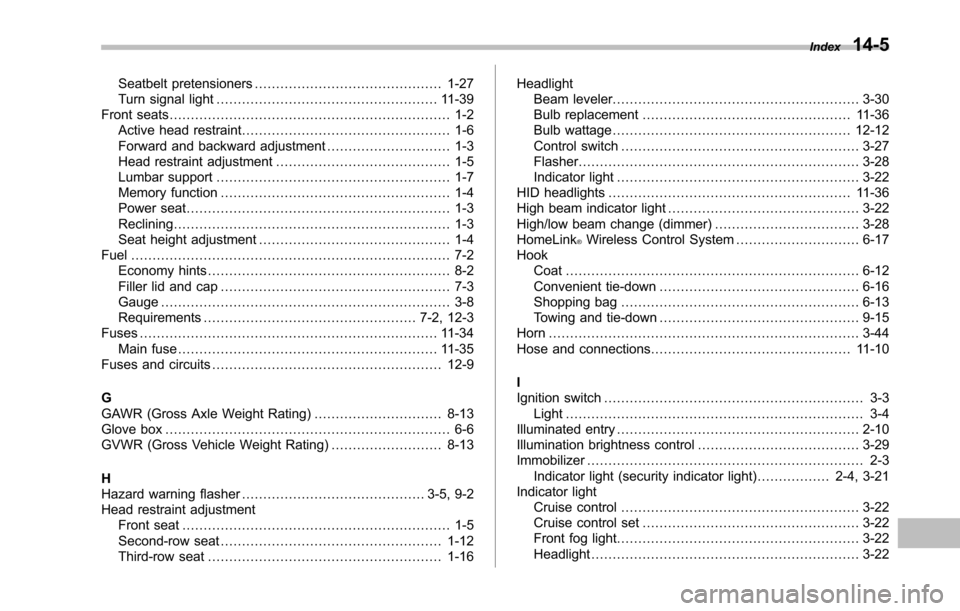
Seatbelt pretensioners............................................ 1-27Turn signal light.................................................... 11-39Front seats.................................................................. 1-2Active head restraint................................................. 1-6Forward and backward adjustment............................. 1-3Head restraint adjustment......................................... 1-5Lumbar support....................................................... 1-7Memory function...................................................... 1-4Power seat.............................................................. 1-3Reclining................................................................. 1-3Seat height adjustment............................................. 1-4Fuel........................................................................... 7-2Economy hints......................................................... 8-2Filler lid and cap...................................................... 7-3Gauge.................................................................... 3-8Requirements.................................................. 7-2, 12-3Fuses...................................................................... 11-34Main fuse............................................................. 11-35Fuses and circuits...................................................... 12-9
GGAWR (Gross Axle Weight Rating).............................. 8-13Glove box................................................................... 6-6GVWR (Gross Vehicle Weight Rating).......................... 8-13
HHazard warning flasher........................................... 3-5, 9-2Head restraint adjustmentFront seat............................................................... 1-5Second-row seat.................................................... 1-12Third-row seat....................................................... 1-16
HeadlightBeam leveler.......................................................... 3-30Bulb replacement................................................. 11-36Bulb wattage........................................................ 12-12Control switch........................................................ 3-27Flasher.................................................................. 3-28Indicator light......................................................... 3-22HID headlights......................................................... 11-36High beam indicator light............................................. 3-22High/low beam change (dimmer).................................. 3-28HomeLink®Wireless Control System............................. 6-17HookCoat..................................................................... 6-12Convenienttie-down............................................... 6-16Shopping bag........................................................ 6-13Towing and tie-down............................................... 9-15Horn......................................................................... 3-44Hose and connections............................................... 11-10
IIgnition switch............................................................. 3-3Light...................................................................... 3-4Illuminated entry......................................................... 2-10Illumination brightness control...................................... 3-29Immobilizer................................................................. 2-3Indicator light (security indicator light)................. 2-4, 3-21Indicator lightCruise control........................................................ 3-22Cruise control set................................................... 3-22Front fog light......................................................... 3-22Headlight............................................................... 3-22
Index14-5