SUZUKI GRAND VITARA 1987 Service Repair Manual
Manufacturer: SUZUKI, Model Year: 1987, Model line: GRAND VITARA, Model: SUZUKI GRAND VITARA 1987Pages: 962, PDF Size: 27.87 MB
Page 231 of 962
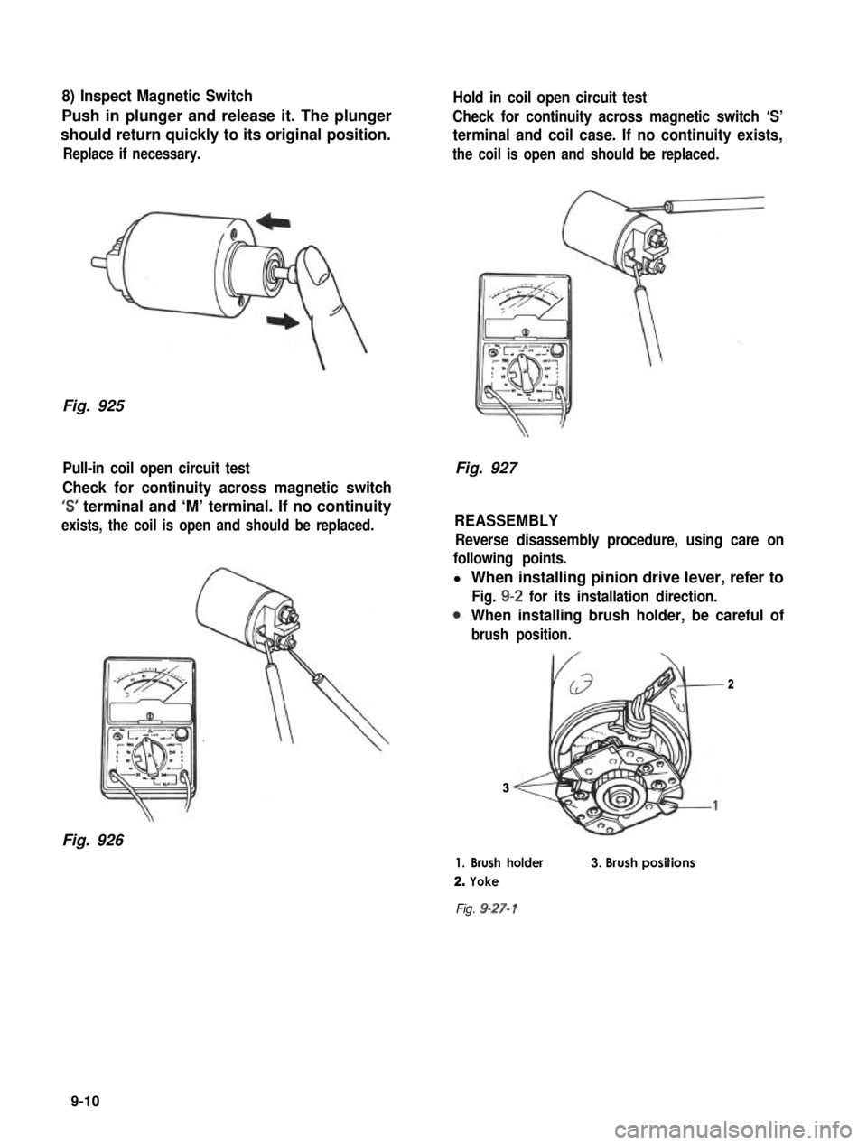
8) Inspect Magnetic SwitchHold in coil open circuit test
Push in plunger and release it. The plungerCheck for continuity across magnetic switch ‘S’
should return quickly to its original position.terminal and coil case. If no continuity exists,
Replace if necessary.the coil is open and should be replaced.
Fig. 925
Pull-in coil open circuit test
Check for continuity across magnetic switch
‘s’ terminal and ‘M’ terminal. If no continuity
exists, the coil is open and should be replaced.
Fig. 926
Fig. 927
REASSEMBLY
Reverse disassembly procedure, using care on
following points.
l When installing pinion drive lever, refer to
Fig. g-2 for its installation direction.
0. When installing brush holder, be careful of
brush position.
2
3
1. Brush holder
2. Yoke
3. Brush positions
Fig. 9-27- 1
9-10
Page 232 of 962
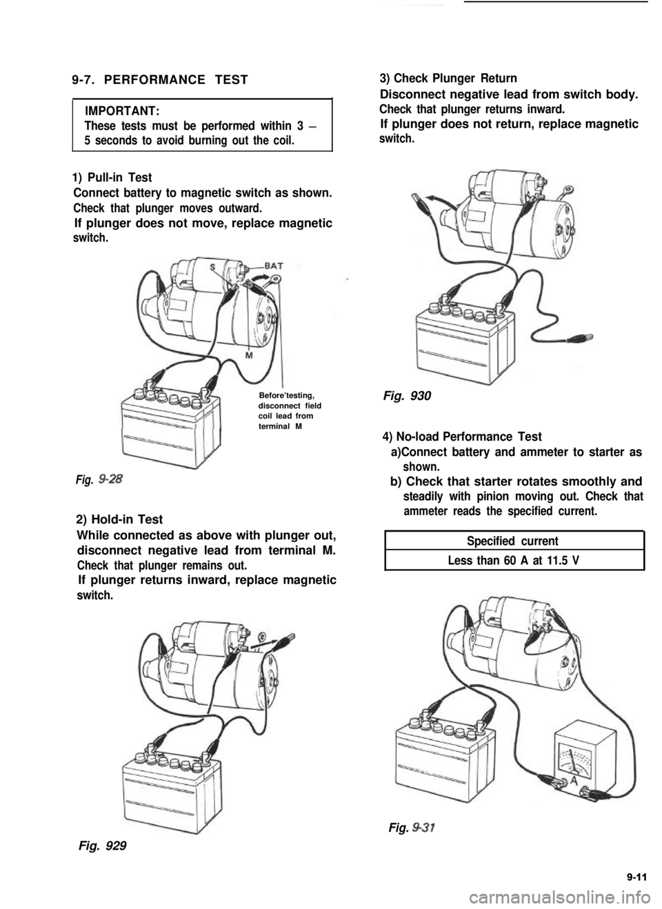
9-7. PERFORMANCE TEST
IMPORTANT:
These tests must be performed within 3 -
5 seconds to avoid burning out the coil.
3) Check Plunger Return
Disconnect negative lead from switch body.
Check that plunger returns inward.
If plunger does not return, replace magnetic
switch.
1) Pull-in Test
Connect battery to magnetic switch as shown.
Check that plunger moves outward.
If plunger does not move, replace magnetic
switch.
Fig.
Before’testing,disconnect fieldcoil lead fromterminal M
w
9-28
2) Hold-in Test
While connected as above with plunger out,
disconnect negative lead from terminal M.
Check that plunger remains out.
If plunger returns inward, replace magnetic
switch. ’
Fig. 930
4) No-load Performance Test
a)Connect battery and ammeter to starter as
shown.
b) Check that starter rotates smoothly and
steadily with pinion moving out. Check that
ammeter reads the specified current.
Specified current
Less than 60 A at 11.5 V
Fig. 931
Fig. 929
9-11
Page 233 of 962
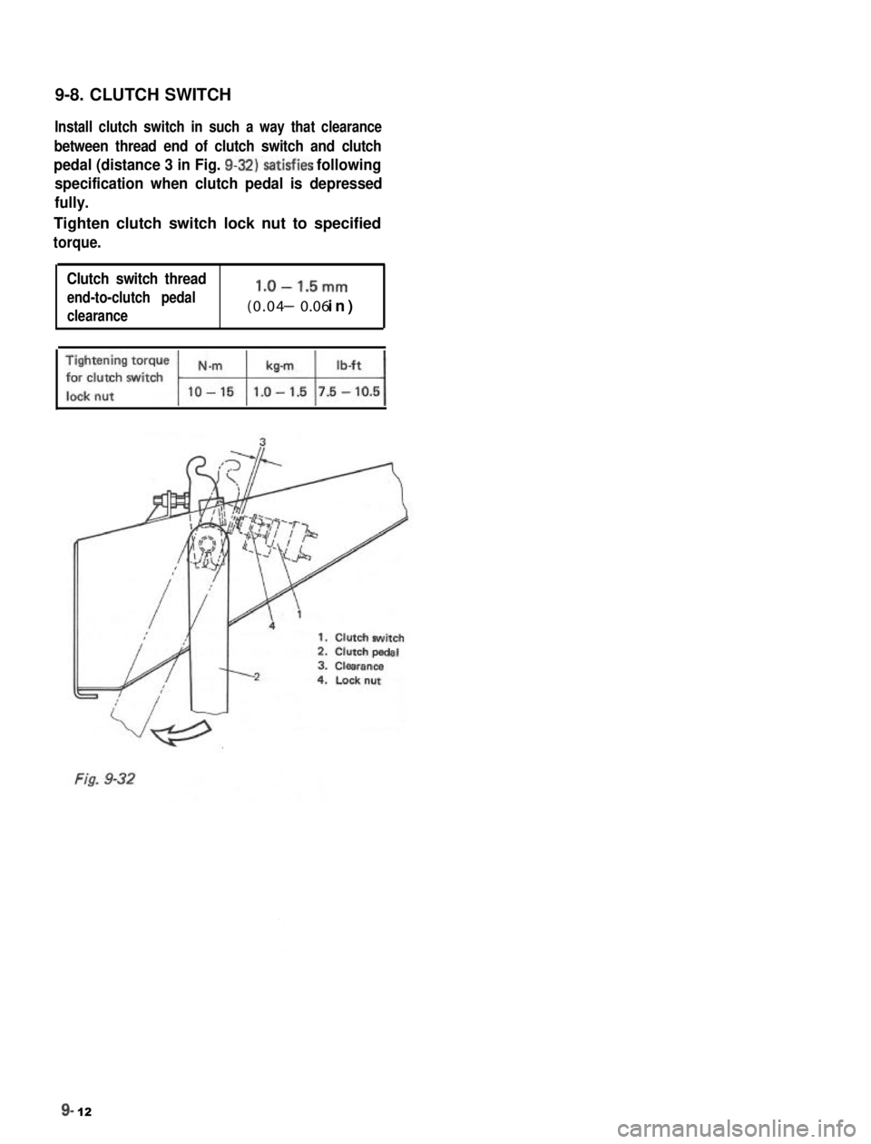
9-8. CLUTCH SWITCH
Install clutch switch in such a way that clearance
between thread end of clutch switch and clutch
pedal (distance 3 in Fig. 9-32)‘satisfies following
specification when clutch pedal is depressed
fully.
Tighten clutch switch lock nut to specified
torque.
Clutch switch thread
end-to-clutch pedall.O-1.5mm
clearance(0.04 - 0.06 in)
9- 12
Page 234 of 962
SECTION 10
CHARGING SYSTEM
CONTENTS
10-l. ALTERNATOR. . . . . . . . . . ..L.............. . . . . . . . . . . .:. . .
GENERAL DESCRIPTION10-2
DATA AND SPECIFICATION...............................10-3
DIAGNOSIS............................................10-3
REMOVAL............................................ 10-6
DISASSEMBLY.........................................10-6
INSPECTION...........................................10-8
ASSEMBLY............................................ 10-9
10-2. BATTERY.............................................10-10
GENERAL DESCRIPTION................................ 10-10
CARE OF THE BATTERY................................10-10
REMOVE AND REPLACE................................ 10-12
BATTERY CABLE...................................... 10-12
..............................
10-2
10
10-1
Page 235 of 962
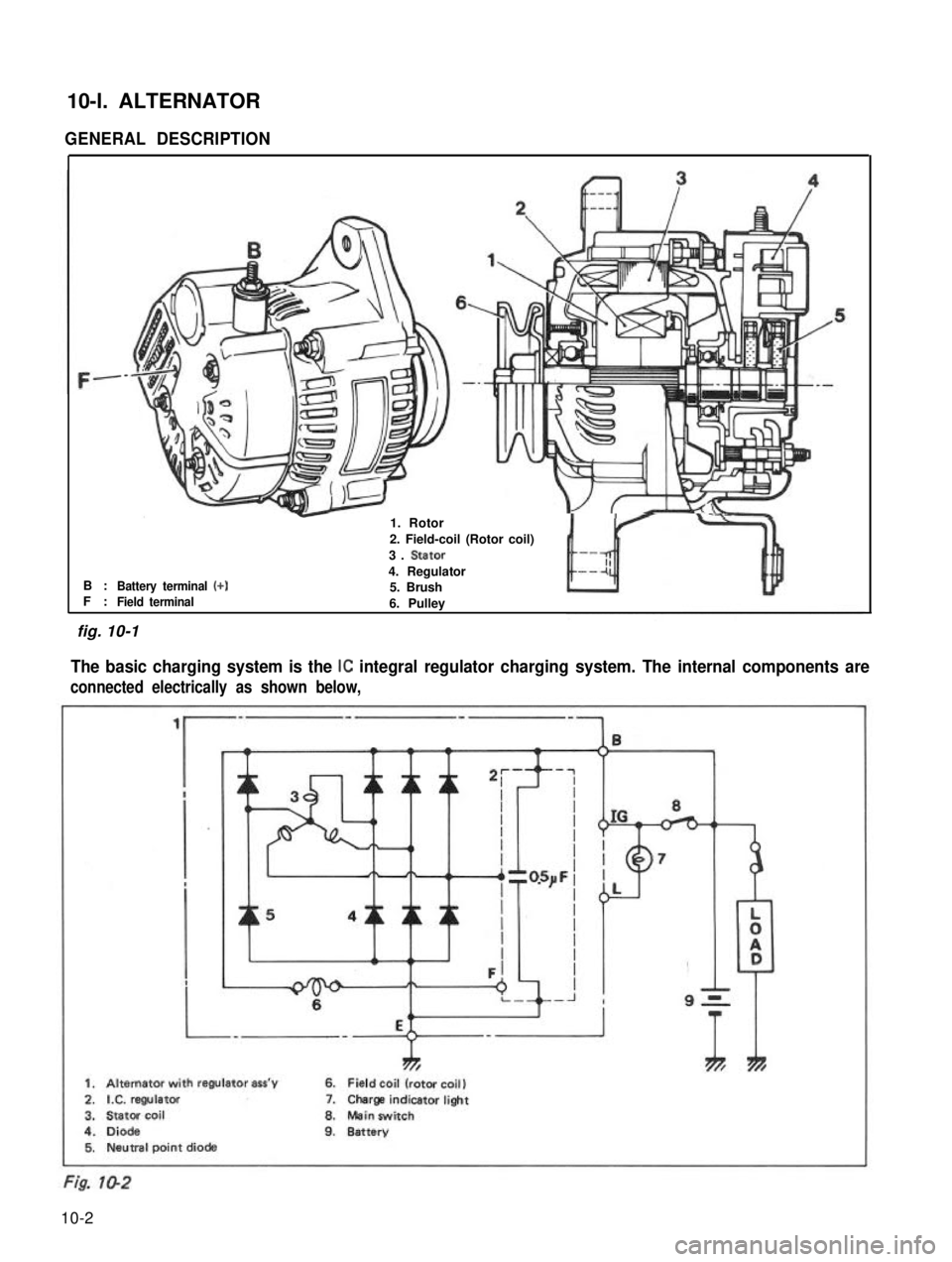
10-l. ALTERNATOR
GENERAL DESCRIPTION
B :F :Battery terminal (+)
-1. Rotor
2. Field-coil (Rotor coil)
3. Stator
4. Regulator5. BrushField terminal6. Pulley
The basic charging system is the IC integral regulator charging system. The internal components are
connected electrically as shown below,
ThTh*
1. Alternator with regulator ass’y6. Field coil (rotor coil)
2.IX. regulator7.Charge indicatorlight
3.Stator coil8.Mein switch
4.Diode9.Battery5. Neutral point diode
fig. 10-1
10-2
Page 236 of 962
The alternator features a solid state regulator
that is mounted inside the alternator. All regula-
tor components are enclosed into a solid mold,
and this unit along with the brush holder assemb-
ly is attached to the slip ring end frame. The
regulator voltage setting cannot be adjusted.
The alternator rotor bearings contain enough
grease to eliminate the need for periodic lubri-
cation. Two brushes carry current through the
two slip rings to the field coil mounted on the
rotor, and under normal conditions will provide
long period of attention-free service.
The stator windings are assembled on the inside
of a laminated core that forms part of the
alternator frame. A rectifier bridge connected
to the stator windings contains six diodes,
and electrically changes the stator A.C. voltages
to a D.C. voltage which appears at the generator
output terminal.
The neutral diodes serve to convert the voltage
fluctuation at the neutral point to direct current
for increasing the alternator output.
A condenser mounted in the end frame protects
the diodes from high voltages and suppresses
radio noise.
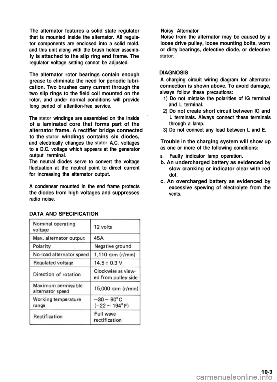
DATA AND SPECIFICATION
Nominal operating
voltaga
Max. alternator output
12 volts
45A
No-load alternator speed
IDirection of rotationClockwise as view-
ed from oullev side
Maximum permissible
alternator speed
Working temperature
range
Rectification
15,000 rpm (r/min)
-3o- 90°C
(-22 - 194” F)
Full wave
rectification
Noisy Alternator
Noise from the alternator may be caused by a
loose drive pulley, loose mounting bolts, worn
or dirty bearings, defective diode, or defective
stator.
DIAGNOSIS
A charging circuit wiring diagram for alternator
connection is shown above. To avoid damage,
always follow these precautions:
1) Do not mistake the polarities of IG terminal
and L terminal.
2) Do not create short circuit between IG and
L terminals. Always connect these terminals
through a lamp.
3) Do not connect any load between L and E.
Trouble in the charging system will show up
as one or more of the following conditions:
a.Faulty indicator lamp operation.
b. An undercharged battery as evidenced by
slow cranking or indicator clear with red
dot.
c. An overcharged battery as evidenced by
excessive spewing of electrolyte from the
vents.
10-3
Page 237 of 962
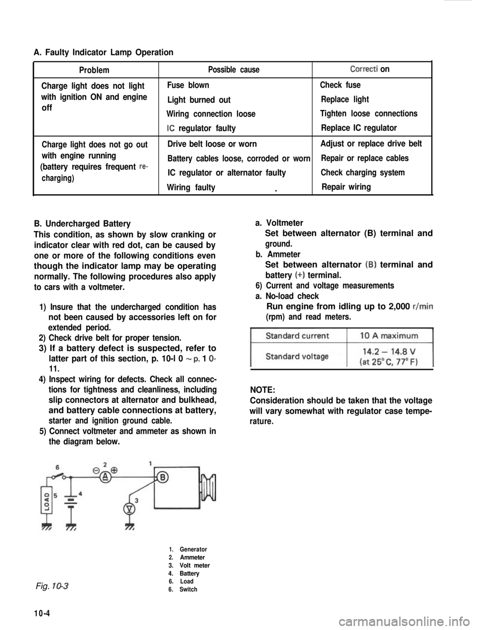
A. Faulty Indicator Lamp Operation
Problem
Charge light does not light
with ignition ON and engine
off
Charge light does not go out
with engine running
(battery requires frequent
re-
charging) Possible cause
Correcti on
Fuse blown
Check fuse
Light burned outReplace light
Wiring connection loose Tighten loose connections
IC regulator faultyReplace IC regulator
Drive belt loose or worn Adjust or replace drive belt
Battery cables loose, corroded or worn Repair or replace cables
IC regulator or alternator faultyCheck charging system
Wiring faulty.Repair wiring
B. Undercharged Battery a. Voltmeter
This condition, as shown by slow cranking or indicator clear with red dot, can be caused by
one or more of the following conditions even
though the indicator lamp may be operating
normally. The following procedures also apply
to cars with a voltmeter.
1) Insure that the undercharged condition has
not been caused by accessories left on for
extended period.
2) Check drive belt for proper tension.
3) If a battery defect is suspected, refer to
latter part of this section, p. 10-l 0 - p, 1 O-
11.
4) Inspect wiring for defects. Check all connec- tions for tightness and cleanliness, including
slip connectors at alternator and bulkhead,
and battery cable connections at battery,
starter and ignition ground cable.
5) Connect voltmeter and ammeter as shown inthe diagram below.
Set between alternator (B) terminal and
ground.
b. Ammeter
Set between alternator (B) terminal and
battery (+) terminal.
6) Current and voltage measurements
a. No-load check
Run engine from idling up to 2,000 r/min
(rpm) and read meters.
NOTE:
Consideration should be taken that the voltage
will vary somewhat with regulator case tempe-
rature.
Fig. 10-3
10-4
1.Generator
2.Ammeter
3. Volt meter
4. Battery
6. Load
6. Switch
Page 238 of 962
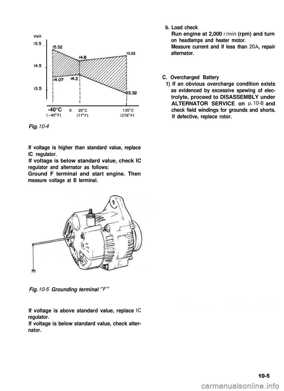
Volt
15.5 . .
14.5 _,
13.5 .,
15.32
15.02
Run engine at 2,000 r/min (rpm) and turn
on headlamps and heater motor.
Measure current and if less than 20A, repair
alternator.
C. Overcharged Battery
1) If an obvious overcharge condition exists
as evidenced by excessive spewing of elec-
trolyte, proceed to DISASSEMBLY underIIIIALTERNATOR SERVICE on p. 10-6 and
-40°C 025Oc135Occheck field windings for grounds and shorts.!-4O“FI(77’F)(275*F)If defective, replace rotor.
b. Load check
Fig. 10-4
If voltage is higher than standard value, replace
IC regulator.
If voltage is below standard value, check IC
regulator and alternator as follows:
Ground F terminal and start engine. Then
measure voltage at B terminal.
Fig. 105 Grounding terminal ‘F”
If voltage is above standard value, replace IC
regulator.
If voltage is below standard value, check alter-
nator.
10-5
Page 239 of 962
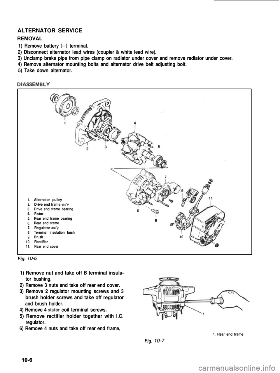
ALTERNATOR SERVICE
REMOVAL
1) Remove battery (-) terminal.
2) Disconnect alternator lead wires (coupler & white lead wire).
3) Unclamp brake pipe from pipe clamp on radiator under cover and remove radiator under cover.
4) Remove alternator mounting bolts and alternator drive belt adjusting bolt.
5) Take down alternator.
DIASSEMBLY
1.Alternator pulley
2.Drive end frame ass’y3.Drive end frame bearing4.Rotor5.Rear end frame bearing
6.Rear end frame7.Regulator aa’y
6.Terminal insulation bush
9.Brush
10.Rectifier11.Rear end cover
‘p” “i6
r10
Fig. 706
1) Remove nut and take off B terminal insula-
tor bushing.
2) Remove 3 nuts and take off rear end cover.
3) Remove 2 regulator mounting screws and 3
brush holder screws and take off regulator
and brush holder.
4) Remove 4 stator coil terminal screws.
5) Remove rectifier holder together with I.C.
regulator.
6) Remove 4 nuts and take off rear end frame,
Fig. 10-7
1. Rear end frame
10-6
Page 240 of 962
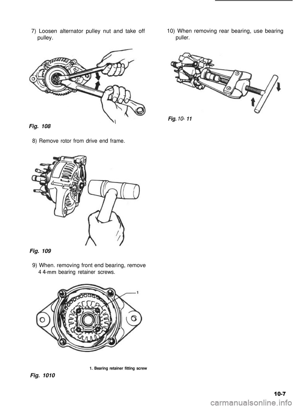
7) Loosen alternator pulley nut and take off
pulley.
10) When removing rear bearing, use bearing
puller.
Fig. 108\Fig. lo- 11
8) Remove rotor from drive end frame.
Fig. 109
9) When. removing front end bearing, remove
4 4-mm bearing retainer screws.
Fig. 1010
1. Bearing retainer fitting screw
10-7