SUZUKI GRAND VITARA 1987 Service Repair Manual
Manufacturer: SUZUKI, Model Year: 1987, Model line: GRAND VITARA, Model: SUZUKI GRAND VITARA 1987Pages: 962, PDF Size: 27.87 MB
Page 251 of 962
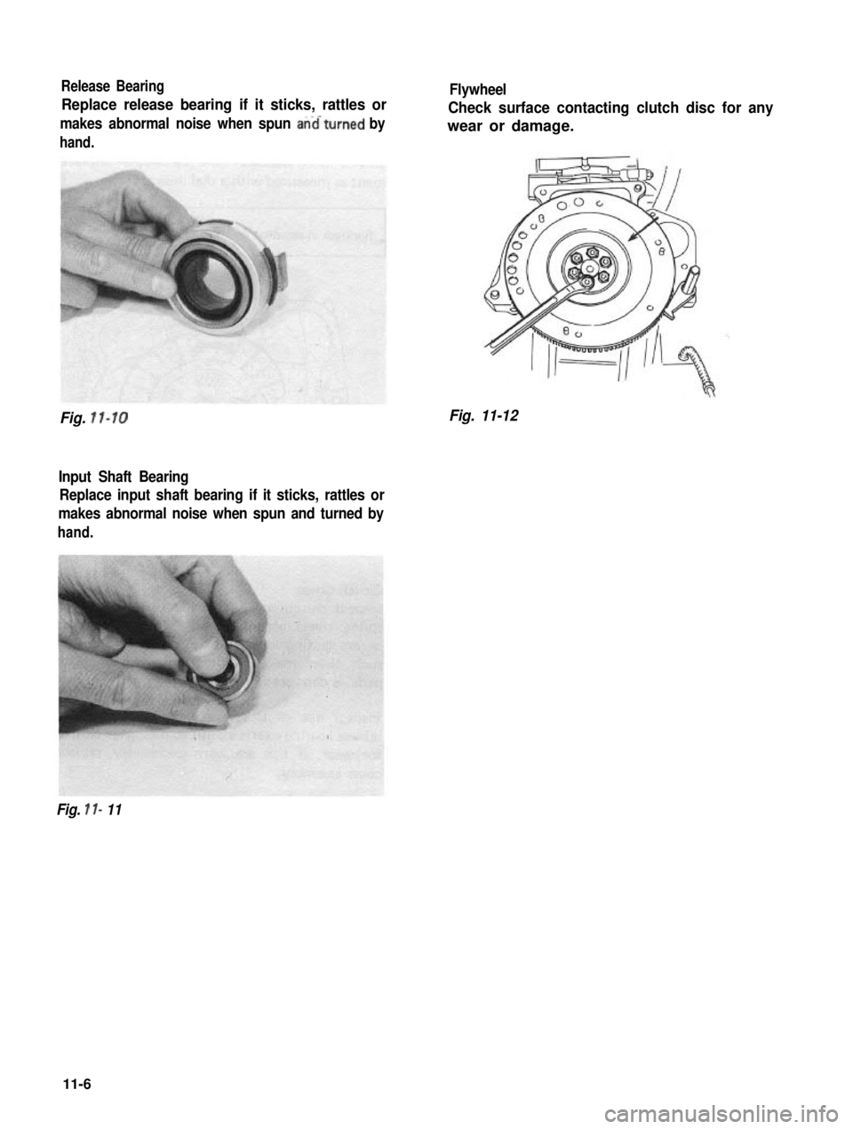
Release Bearing
Replace release bearing if it sticks, rattles or
makes abnormal noise when spun anaturned by
hand.
Fig. 11-10
Input Shaft Bearing
Replace input shaft bearing if it sticks, rattles or
makes abnormal noise when spun and turned by
hand.
Flywheel
Check surface contacting clutch disc for any
wear or damage.
Fig. 11-12
Fig. 1 I- 11
11-6
Page 252 of 962
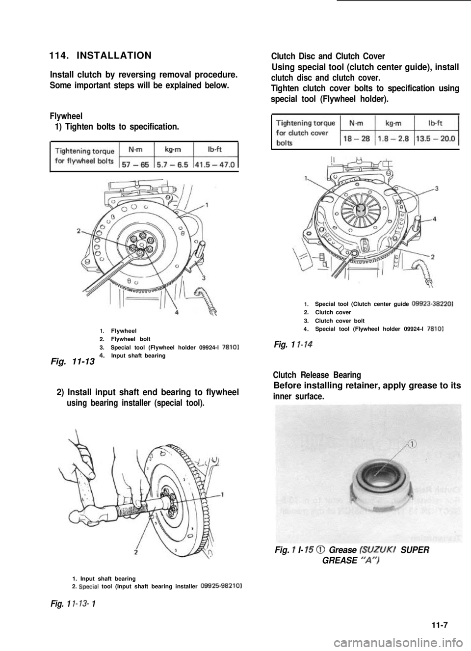
114. INSTALLATION
Install clutch by reversing removal procedure.
Some important steps will be explained below.
Flywheel
1) Tighten bolts to specification.
1.Flywheel
2.Flywheel bolt
3.Special tool (Flywheel holder 09924-l 7810)
Fig. 11-13 4*Input shaft bearing
2) Install input shaft end bearing to flywheel
using bearing installer (special tool).
1. Input shaft bearing2. Special tool (Input shaft bearing installer 09925-98210)
Fig. 1 l- 13- 1
Clutch Disc and Clutch Cover
Using special tool (clutch center guide), install
clutch disc and clutch cover.
Tighten clutch cover bolts to specification using
special tool (Flywheel holder).
1.2.
3.
4.
Fig. 1 l-14
Special tool (Clutch center guide 09923-38220)
Clutch cover
Clutch cover boltSpecial tool (Flywheel holder 09924-l 7810)
Clutch Release Bearing
Before installing retainer, apply grease to its
inner surface.
Fig. 1 I- 15 @ Grease (SUZUKI SUPER
GREASE “A’,)
11-7
Page 253 of 962
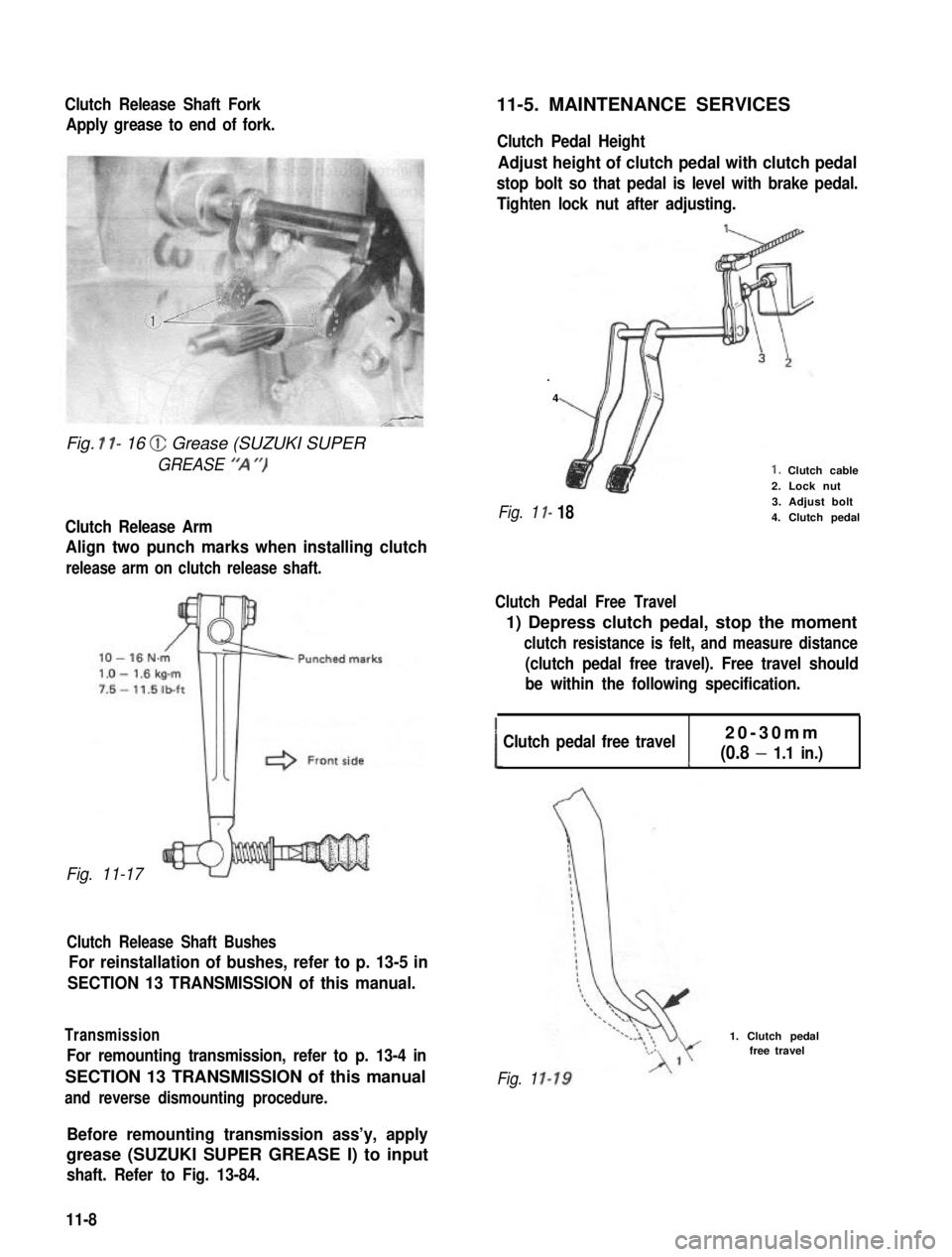
Clutch Release Shaft Fork
Apply grease to end of fork.
Fig. I l- 16 @ Grease (SUZUKI SUPER
GREASE “‘A “)
Clutch Release Arm
Align two punch marks when installing clutch
release arm on clutch release shaft.
Fig. 11-17
Clutch Release Shaft Bushes
For reinstallation of bushes, refer to p. 13-5 in
SECTION 13 TRANSMISSION of this manual.
Transmission
For remounting transmission, refer to p. 13-4 in
SECTION 13 TRANSMISSION of this manual
and reverse dismounting procedure.
11-5. MAINTENANCE SERVICES
Clutch Pedal Height
Adjust height of clutch pedal with clutch pedal
stop bolt so that pedal is level with brake pedal.
Tighten lock nut after adjusting.
.
4
I-
I- 18
1. Clutch cable2. Lock nut3. Adjust bolt4. Clutch pedalFig. 1
Clutch Pedal Free Travel
1) Depress clutch pedal, stop the moment
clutch resistance is felt, and measure distance
(clutch pedal free travel). Free travel should
be within the following specification.
!Clutch pedal free travel20-30mm
(0.8 - 1.1 in.)c
Fig. 1
1. Clutch pedalfree travel
Before remounting transmission ass’y, apply
grease (SUZUKI SUPER GREASE I) to input
shaft. Refer to Fig. 13-84.
11-8
Page 254 of 962
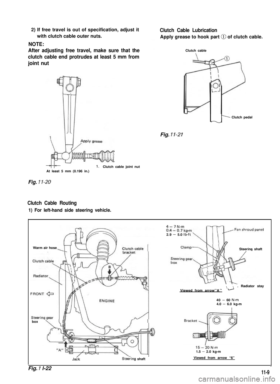
2) If free travel is out of specification, adjust it
with clutch cable outer nuts.
NOTE:
After adjusting free travel, make sure that the
clutch cable end protrudes at least 5 mm from
joint nut
1.Clutch cable joint nutAt least 5 mm (0.196 in.)
Fig. 1 l-20
Clutch Cable Routing
1) For left-hand side steering vehicle.
Clutch Cable Lubrication
Apply grease to hook part @ of clutch cable.
Clutch cable
1 Clutch pedaly-v
Fig. 11-21
Warm air hose
box -
Jadk
15-i0N.m1.5 - 2.0 kg-m
SteeTing shaft’Viewed from arrow “6”
4-7N.m
2.9- 5.0lb-ft
Steerina shaft
/ -
\. Radiator stayI, ,IViewed from arrow A-
40 - 60 N.m4.0 - 6.0 kg-m
I
Fig. 1 l-221
11-9
Page 255 of 962
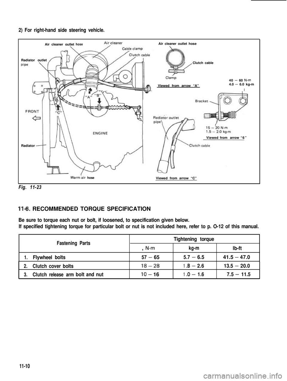
2) For right-hand side steering vehicle.
Air cleaner outlethoseAircleaner
Radiator outlet
Air cleaner outlet hose
Clutch cable
Cla&p
Viewed from arrow “A”
40 - 60 N.m4.0 - 6.0 kg-m
I
Viewedfrom arrow“6”
Radiator
Fig. 11-23
Warmair hoseViewed from arrow “C”
11-6. RECOMMENDED TORQUE SPECIFICATION
Be sure to torque each nut or bolt, if loosened, to specification given below.
If specified tightening torque for particular bolt or nut is not included here, refer to p. O-12 of this manual.
Fastening PartsTightening torque
, N.mkg-mlb-ft
1.Flywheelbolts57-655.7-6.541.5-47.0
2.Clutchcover bolts18-281.B-2.613.5-20.0
3.Clutchrelease armboltandnutlo- 161.O-1.67.5-11.5.
11-10
Page 256 of 962
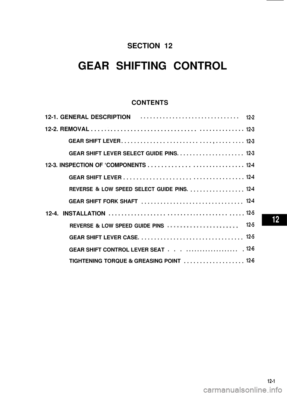
SECTION 12
GEAR SHIFTING CONTROL
CONTENTS
12-1. GENERAL DESCRIPTION
12-2. REMOVAL . . . . .; . . . . . . . . . . . . . . . . . . . . . . . . . .. . . . . . . . . . . . . .
GEAR SHIFT LEVER. . . . . . . . . . . . . .. . . . . . . . . .. . . . , . . . . .. . . .
GEAR SHIFT LEVER SELECT GUIDE PINS. . . . . . . . . . . . . . . . . . . . .
12-3. INSPECTION OF ‘COMPONENTS . . . . . . . . . . . . .. . . . . . . . . . . . . . . .
GEAR SHIFT LEVER . . . . . . . . . . . . . . . . . . . . .. . . . . . . . . . . . . . . .
REVERSE & LOW SPEED SELECT GUIDE PINS..................
GEAR SHIFT FORK SHAFT................................
12-4. INSTALLATION. . . . . . . . . . . . . . . . . .. . . . . . . . * . . . . . . . . . .. . . . .
REVERSE & LOW SPEED GUIDE PINS......................
GEAR SHIFT LEVER CASE.................................
GEAR SHIFT CONTROL LEVER SEAT. . . ....................
TIGHTENING TORQUE & GREASING POINT. . . . . . . . . . . . . . . . . . .
12-1
...............................12-2
12-3
12-3
12-3
12-4
12-4
12-4
12-4
12-5
12-5
12-5
12-6
12-6
12
Page 257 of 962
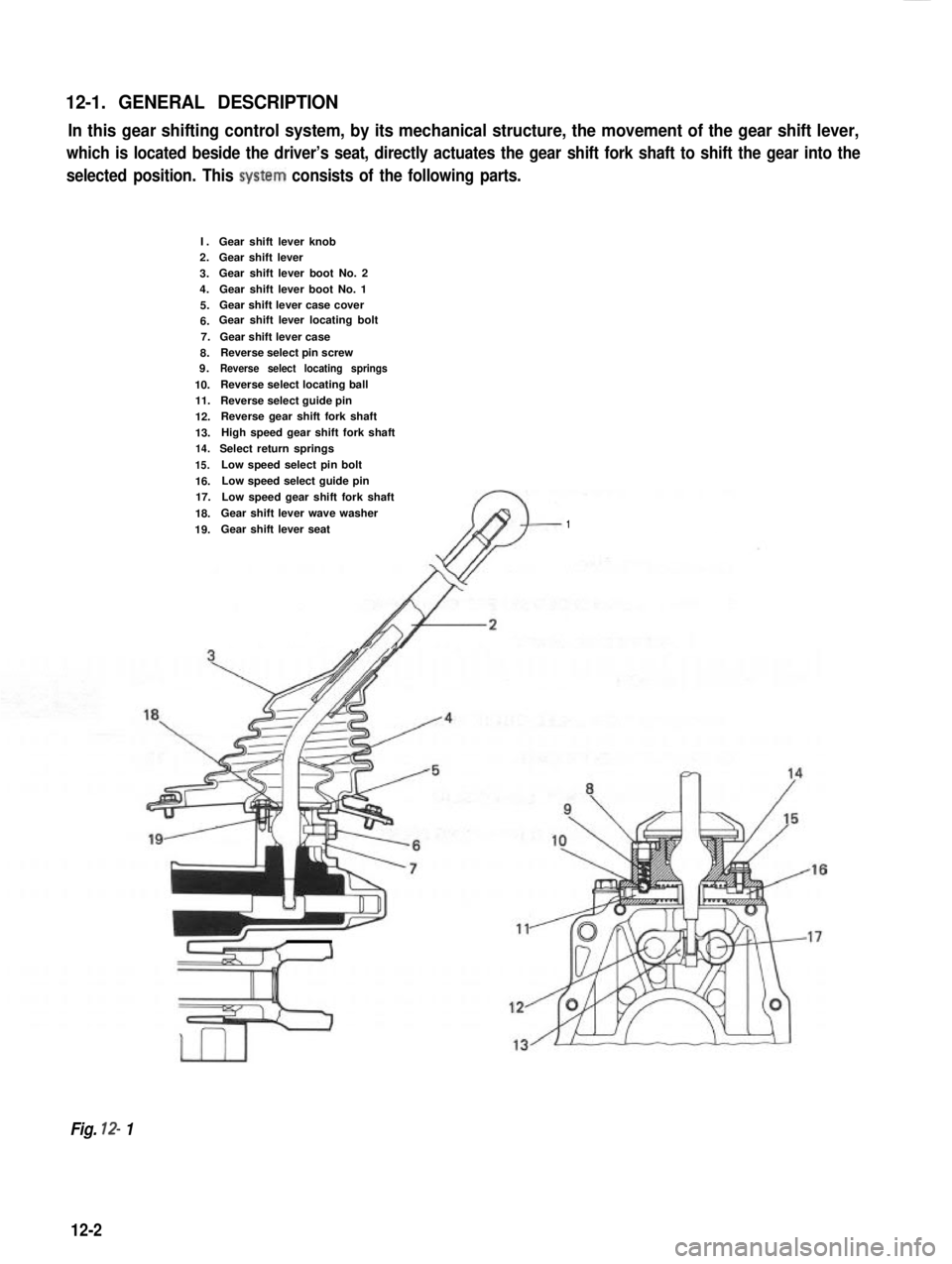
12-1. GENERAL DESCRIPTION
In this gear shifting control system, by its mechanical structure, the movement of the gear shift lever,
which is located beside the driver’s seat, directly actuates the gear shift fork shaft to shift the gear into the
selected position. This system consists of the following parts.
I.2.
3.4.
5.6.7.
8.9.
10.11.
12.
13.14.
15.
16.17.
18.
19.
Gear shift lever knobGear shift leverGear shift lever boot No. 2
Gear shift lever boot No. 1Gear shift lever case coverGear shift lever locating bolt
Gear shift lever caseReverse select pin screwReverse select locating springs
Reverse select locating ball
Reverse select guide pinReverse gear shift fork shaft
High speed gear shift fork shaft
Select return springs
Low speed select pin bolt
Low speed select guide pin
Low speed gear shift fork shaft
Gear shift lever wave washer
Gear shift lever seat1
Fig. 12- 1
12-2
Page 258 of 962
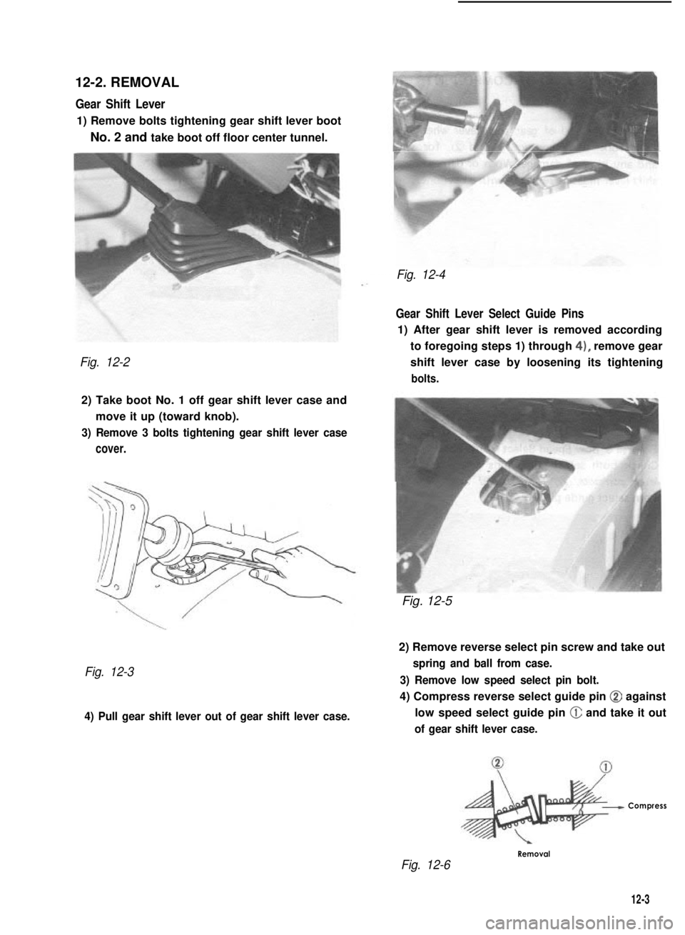
12-2. REMOVAL
Gear Shift Lever
1) Remove bolts tightening gear shift lever boot
No. 2 and take boot off floor center tunnel.
Fig. 12-2
2) Take boot No. 1 off gear shift lever case and
move it up (toward knob).
3) Remove 3 bolts tightening gear shift lever case
cover.
Fig. 12-3
4) Pull gear shift lever out of gear shift lever case.
Fig. 12-4
Gear Shift Lever Select Guide Pins
1) After gear shift lever is removed according
to foregoing steps 1) through 4), remove gear
shift lever case by loosening its tightening
bolts.
Fig. 12-5
2) Remove reverse select pin screw and take out
spring and ball from case.
3) Remove low speed select pin bolt.
4) Compress reverse select guide pin @ against
low speed select guide pin @ and take it out
of gear shift lever case.
Compress
Fig. 12-6
Removal
12-3
Page 259 of 962
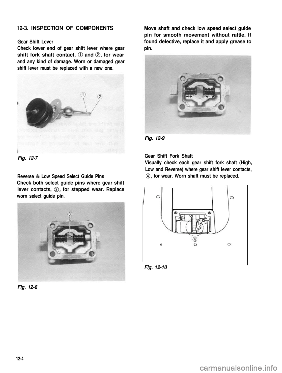
12-3. INSPECTION OF COMPONENTS
Gear Shift Lever
Check lower end of gear shift lever where gear
shift fork shaft contact, @ and 0, for wear
and any kind of damage. Worn or damaged gear
shift lever must be replaced with a new one.
Fig. 12-7
Reverse & Low Speed Select Guide Pins
Check both select guide pins where gear shift
lever contacts, 0, for stepped wear. Replace
worn select guide pin.
Move shaft and check low speed select guide
pin for smooth movement without rattle. If
found defective, replace it and apply grease to
pin.
Fig. 12-9
Gear Shift Fork Shaft
Visually check each gear shift fork shaft (High,
Low and Reverse) where gear shift lever contacts,
@, for wear. Worn shaft must be replaced.
I
0
0
Fig. 12-10
Fig. 12-8
12-4
Page 260 of 962
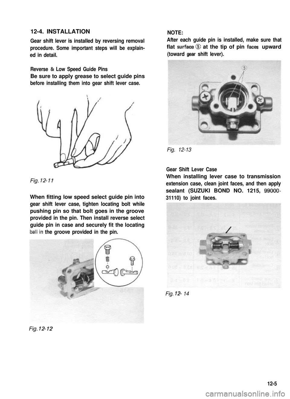
12-4. INSTALLATION
Gear shift lever is installed by reversing removal
procedure. Some important steps will be explain-
ed in detail.
NOTE:
After each guide pin is installed, make sure that
flat surfaca @I at the tip of pin faces upward
(toward gear shift lever).
Reverse & Low Speed Guide Pins
Be sure to apply grease to select guide pins
before installing them into gear shift lever case.
Fig. 12- 11
When fitting low speed select guide pin into
gear shift lever case, tighten locating bolt while
pushing pin so that bolt goes in the groove
provided in the pin. Then install reverse select
guide pin in case and securely fit the locating
balkin the groove provided in the pin.
Fig. 12-13
Gear Shift Lever Case
When installing lever case to transmission
extension case, clean joint faces, and then apply
sealant (SUZUKI BOND NO. 1215, 99009
31110) to joint faces.
Fig. 12- 14
Fig. 12- 12
12-5