SUZUKI GRAND VITARA 1987 Service Repair Manual
Manufacturer: SUZUKI, Model Year: 1987, Model line: GRAND VITARA, Model: SUZUKI GRAND VITARA 1987Pages: 962, PDF Size: 27.87 MB
Page 331 of 962

16-5. REASSEMBLY
Reverse disassembly procedure for reassembly,
noting the following.
NOTE:
Bevel pinion and bevel gear are supplied as a
set. Even when only bevel pinion or bevel gear
replacement is necessary, be sure to replace
both as a set.
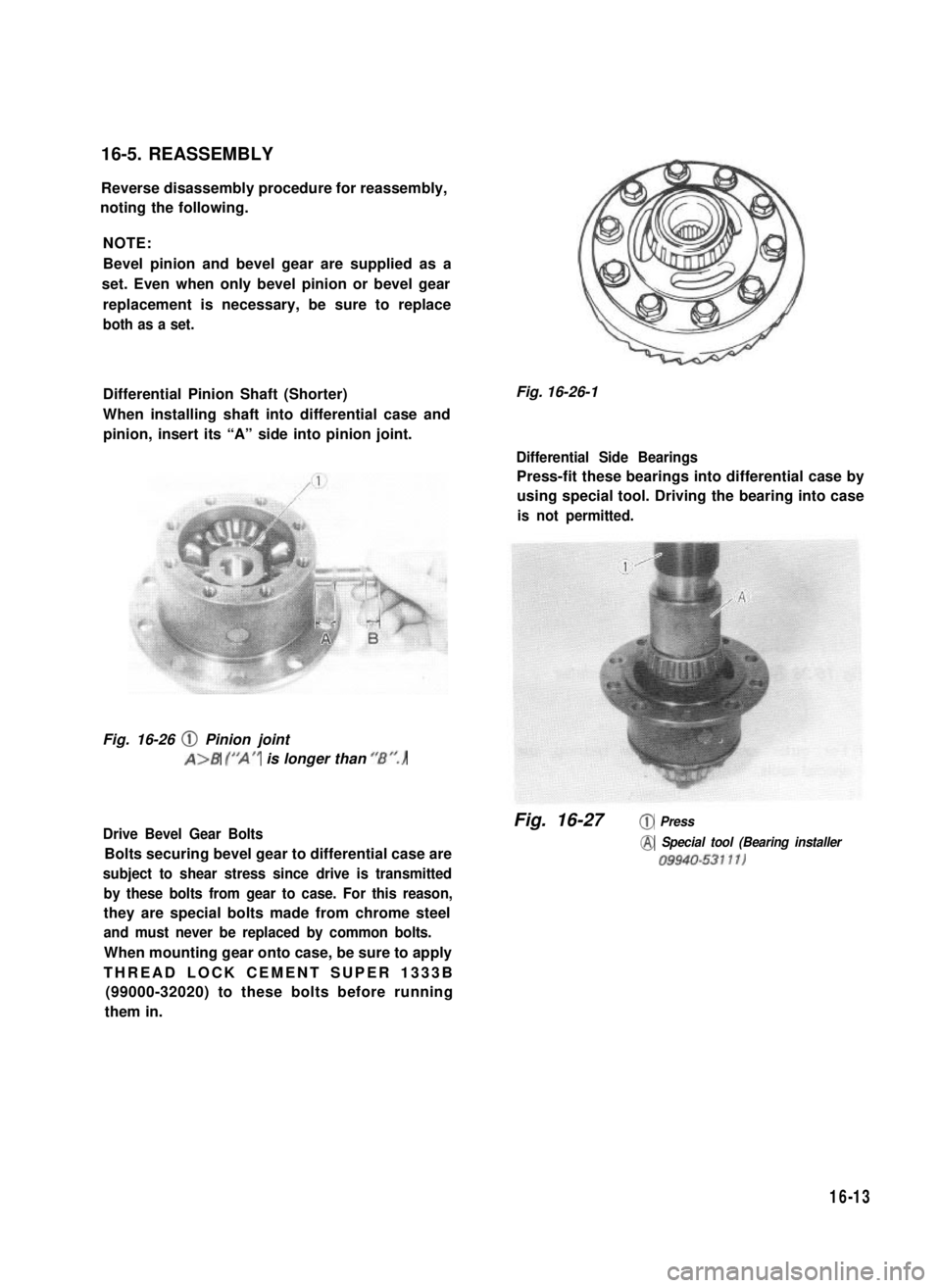
Differential Pinion Shaft (Shorter)
When installing shaft into differential case and
pinion, insert its “A” side into pinion joint.
Fig. 16-26 @ Pinion joint
A>B (“A” is longer than ‘/Br’.)
Drive Bevel Gear Bolts
Bolts securing bevel gear to differential case are
subject to shear stress since drive is transmitted
by these bolts from gear to case. For this reason,
they are special bolts made from chrome steel
and must never be replaced by common bolts.
When mounting gear onto case, be sure to apply
THREAD LOCK CEMENT SUPER 1333B
(99000-32020) to these bolts before running
them in.
Fig. 16-26-1
Differential Side Bearings
Press-fit these bearings into differential case by
using special tool. Driving the bearing into case
is not permitted.
Fig. 16-27@ Press
@ Special tool (Bearing installer
09940-53111)
16-13
Page 332 of 962

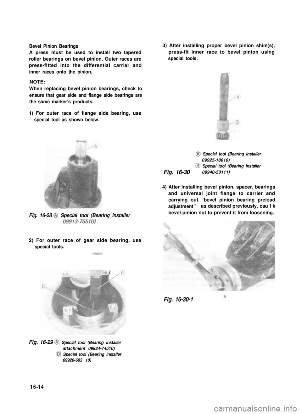
Bevel Pinion Bearings
A press must be used to install two tapered
roller bearings on bevel pinion. Outer races are
press-fitted into the differential carrier and
inner races onto the pinion.
NOTE:
When replacing bevel pinion bearings, check to
ensure that gear side and flange side bearings are
the same marker’s products.
1) For outer race of flange side bearing, use
special tool as shown below.
Fig. 16-28 @ Special tool (Bearing installer
09913-75510)
2) For outer race of gear side bearing, use
special tools.
3) After installing proper bevel pinion shim(s),
press-fit inner race to bevel pinion using
special tools.
@ Special tool (Bearing installer
09925-18010)
Fig. 16-30
@ Special tool (Bearing installer
09940-53111)
4) After installing bevel pinion, spacer, bearings
and universal joint flange to carrier and
carrying out “bevel pinion bearing preload
adjustment”as described previously, cau I k
bevel pinion nut to prevent it from loosening.
Fig. 16-30-1
Fig. 16-29 @ Special tool (Bearing installer
attachment 09924-74510)
@ Special tool (Bearing installer
09926-683 10)
16-14
Page 333 of 962

Side Bearings Caps
When putting on side bearing caps, be sure to
discriminate the right-hand cap from the left-
hand one by referring to match marks scribed
at the time of disassembly.
Then, after carrying out “Bevel gear backlash
adjustment” as described on p. 16-10 torque cap
bolts to specification.
16-6. INSTALLATION
Reverse removal procedure for installation,
noting the following.
Differential
Before installing differential ass’y to axle hous-
ing, clean mating surfaces of differential carrier
and housing and apply sealant to them.
Fig. 16-31 0 Scribed match marks
Fig. 16-32 @ Sealant (SUZUKI BOND NO.
1215 99000-31110)
Front Axle Shaft and Steering Knuckle
For installation them, refer to “Front Suspen-
sion Installation” in SECTION 17 of this manual.
Rear Brake Drum
For installation of rear brake drum, refer to
“Rear Brake Installation” in SECTION 19 of
this manual.
Differential Gear Oil
Refill differential housing with new specified
oil. Refer to “MAINTENANCE SERVICE” in
this section for refill.
Brake Circuit Air Purging
If brake pipe (right & left) was disconnected
from wheel cylinder as in Fig. 16-9-2, make sure
to purge air out of brake circuit. Refer to
section 19. BRAKES for “air purging" operation.
Then check to ensure that joint seam of pipe is
free from oil leak.
16-15
Page 334 of 962

16-7. MAINTENANCE SERVICES
Inspection
Inspect differential and differential housing for
evidence of oil leakage.
Oil level ‘is checked by means of its oil level
plug. Refer to p 1-20 for level inspection,
Fig. 16-33 @ Drain plug
CD Oil level & filler plug
Oil Change
1 ) Remove oil drain plug and drain oil.
2) Reinstall drain plug and tighten it to specified
tightening torque.
3) Remove oil level & filler plug and fill diffe-
rential housing with new specified oil.
Differential oilHypoid gear oil
specificationSAE 8OW-90,75W-80 or 75W-90
OilFront2.0 litres (4.2/3.5 US/Imp pt.)
capacityRear1.5 litres (3.2/2.6 US/Imp pt.)
It is highly recommended to use SAE 75W-90
gear oil.
For viscosity chart, refer to P. 1-20.
16-8. RECOMMENDED TORQUE
SPECIFICATIONS
ITightening torqueI
IFastening partsN.m1 kg-m 11
Side bearing capbolt70- 1007.0-10.051 .O-72.0
Drive bevel gearbolt80- 908.0-9.058.0-66.0
Differential casebolt37-453.7-4.527.0-32.5I
4) Reinstall oil level & filler plug and tighten it
to specified tightening torque.
16-16
Side bearing adjusterlock bolt
Differential carrier bolt
Oil level & filler plug
Oil drain plug
Page 335 of 962

SECTION 17
SUSPENSION
CONTENTS
17-1. FRONT SUSPENSION. . . . . . . . . . . . . . . . . . . . . . . . . . . . . . . . . . . . . . 17-2
17-2. REAR SUSPENSION . . . . . . . . . . . . . . . . . . . . . . . . . . . . . . . . . . . . . . 17-15
17-3. MAINTENANCE SERVICES.. . . . . . . . . . . . . . . . . . . . . . . . . . . . . . . 17-20
17-4. RECOMMENDED TORQUE SPECIFICATIONS.. . . . . . . . . . . . . . . . 17-26
17-5. FRONT FREE WHEELING HUB (OPTIONAL) . . . . . . . . . . . . . . . . . 17-27
NOTE:
l All suspension fasteners are an important attaching part in that it could affect the
performance of vital parts and systems, and/or could result in major repair expense.
They must be replaced with one of the same part number or with an equivalent part if
replacement becomes necessary. Do not use a replacement part of lesser quality or
substitute design. Torque values must be used as specified during reassembly to assure
proper retention of this part.
l Never attempt to heat, quench or straighten any suspension part. Replace it with a new
part, or damage to the part may result.
l The leaf spring number or shape shown in this manual may differ from the car being
actually serviced, depending on specification.
17-1
Page 336 of 962

17-1. FRONT SUSPENSION
GENERAL DESCRIPTION
The front suspension consists of the double-acting shock absorbers, stabilizer bar, semi-elliptical leaf
springs, axle housing, etc. as shown below.
The Barfield universal joints are used in the front axle to enable the axle shafts to drive the front wheels
while allowing the wheels to be steered. This type of joint provides for a larger steering angle range and,
what is more important, constant-velocity drive to the wheel.
If a single two-yoke (or Hooke’s) universal joint is used to connect the axle shaft to the wheel on each
side of the front end, the wheels will run with the same speed, but not with the same constant velocity, as
that of the axle shafts when the wheels are turned around their kingpins for steering action. The Barfield
joint transmits drive without varying the angular velocity of drive.
The Barfield joint is enclosed by the knuckle, which is shaped integral with the knuckle arm, and has a
two-piece kingpin, namely, upper and lower kingpins.
The end of the dead axle sleeve is in the shape of dish. This dish is rotatably fitted into the knuckle
structure to form a flexible connection, the sliding clearance between the two being sealed with a felt
packing (against road dust and mud) and also with an oil seal (against the oil inside). The upper and lower
kingpins, bolted to the knuckle extend into the knuckle and, inside, are held by the dish-like inner case
through tapered roller bearings.
BushWasher
Front axle housing
Oil seal cover
retainer ISteeringLn,,rlrlo
Front wheel hub
Front wheel bearing
1\;lEkl bearing nutFront wheelbearina
Shacklebush
outerplateASta ilizer\drive flange
nut
Fig. 17-1-1
17-2
Page 337 of 962

1. Front brake disc
2.Wheel bearing
3. Axle shaft drive flange4.Wheel hub
5.Dust cover6.Oil seal7.King pin8. King pin bearing
9.Oil seal
10.Steering knuckle
11. Disc brake holder12. Disc brake caliper
13.Shock absorber
14.Spring bumper
15. Axle shaft joint16.Leaf spring
17-3
Fig. 17-1-2
Page 338 of 962

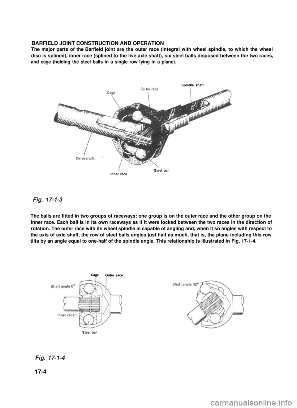
BARFIELD JOINT CONSTRUCTION AND OPERATION
The major parts of the Barfield joint are the outer race (integral with wheel spindle, to which the wheel
disc is splined), inner race (splined to the live axle shaft), six steel balls disposed between the two races,
and cage (holding the steel balls in a single row lying in a plane).
Spindle shaft
IInner raceSteel ball
The balls are fitted in two groups of raceways; one group is on the outer race and the other group on the
inner race. Each ball is in its own raceways as if it were locked between the two races in the direction of
rotation. The outer race with its wheel spindle is capable of angling and, when it so angles with respect to
the axis of axle shaft, the row of steel balls angles just half as much, that is, the plane including this row
tilts by an angle equal to one-half of the spindle angle. This relationship is illustrated in Fig. 17-1-4.
CageOuter race
Steel ball
17-4
Fig. 17-1-3
Fig. 17-1-4
Page 339 of 962

REMOVAL
Shock Absorber
The shock absorber is non-adjustable, non-
refillable, and cannot be disassembled.
The only service the shock absorber requires is
replacement when it has lost its resistance, is
damaged, or leaking fluid.
1. Hoist car.
2. Loosen lower and upper mounting nuts and
remove shock absorber.
7Shacklepin
Washer
Fig. 17-1-6
Washer
Washer
by
D
Nut
Stabilizer
1. Hoist car.
2. Remove stabilizer bolts.
3. After removing stabilizer mount bush
bracket bolts, remove stabilizer.
Fig. 17-1-5
Leaf Spring
1. Raise car. In this operation, garage jack or
hoist must not be positioned against front
suspension related parts. When garage jack
is used, place safety stands under chassis to
support raised body.
2. Remove front wheel.
3. Remove stabilizer bolt.
4. Remove U-bolt nuts.
5. Remove shackle nuts and leaf spring nut.
NOTE:
Removal of leaf spring causes axle housing to
hang. Support it with safety stand to prevent it
from damaging universal joint of propeller shaft
and others.
Stabilizer
F
fBracket boltFig. 17-1-7
6. Pull out leaf spring bolt and remove leaf
spring from shackle pin.
17-5
Page 340 of 962

Front Wheel Hub 81 Bearing
1. Loosen the five nuts securing the wheel.
Raise the front end by jacking.
Rest the machine steady on safety stands.
2. Remove the five nuts and take off the wheel.
Fig. 17-1-8
3. Remove the caliper with carrier by loosen-
ing carrier bolts.
NOTE:
Hang removed caliper with a wire hook or the
like so as to prevent brake hose from bending
and twisting excessively or being pulled.
Don’t operate brake pedal with caliper removed.
Fig. 17-1-9
4. Remove brake disc.
NOTE:
If brake disc can not be removed by hand, use
8 mm bolts as shown below.
f
@
[For car equipped with free wheeling hub]
5. Remove free wheeling hub cover and circlip.
Fig. 17-1-12-1 @ Circlip remover (09900-06107)
6. Remove free wheeling hub body.
Fig. 17-1-10
17-6Fig. 17-1-12-2
8mm BoltFig. 17-1-11