SUZUKI GRAND VITARA 1987 Service Repair Manual
Manufacturer: SUZUKI, Model Year: 1987, Model line: GRAND VITARA, Model: SUZUKI GRAND VITARA 1987Pages: 962, PDF Size: 27.87 MB
Page 371 of 962
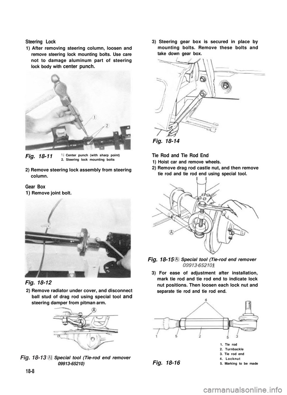
Steering Lock
1) After removing steering column, loosen and
remove steering lock mounting bolts. Use care
not to damage aluminum part of steering
lock body with center punch.
Fig. 18-11 1. Center punch (with sharp point)2. Steering lock mounting bolts
2) Remove steering lock assembly from steering
column.
Gear Box
1) Remove joint bolt.
Fig. 18-12
2) Remove radiator under cover, and disconnect
ball stud of drag rod using special tool and
steering damper from pitman arm.
-----‘CA2
@ Special tool (Tie-rod end remover
09913-65210)
18-8
3) Steering gear box is secured in place by
mounting bolts. Remove these bolts and
take down gear box.
Fig. 18-14
Tie Rod and Tie Rod End
1) Hoist car and remove wheels.
2) Remove drag rod castle nut, and then remove
tie rod and tie rod end using special tool.
I I
Fig. 18-15 @ Special tool (Tie-rod end remover
09913-65210)
3) For ease of adjustment after installation,
mark tie rod and tie rod end to indicate lock
nut positions. Then loosen each lock nut and
separate tie rod and tie rod end.
Fig. 18-16
1. Tie rod
2. Turnbackle
3. Tie rod end
4. Locknut
5. Marking to be made
Fig. 18-13
Page 372 of 962
![SUZUKI GRAND VITARA 1987 Service Repair Manual 18-5. INSPECTION OF COMPONENTS
Steering Gear Box
[Oil level]
Oil surface should be up to the level as shown
in below figures. If not, add prescribed gear oil,
SAE 90.
Right hand steering vehicle
Fig. SUZUKI GRAND VITARA 1987 Service Repair Manual 18-5. INSPECTION OF COMPONENTS
Steering Gear Box
[Oil level]
Oil surface should be up to the level as shown
in below figures. If not, add prescribed gear oil,
SAE 90.
Right hand steering vehicle
Fig.](/img/20/57437/w960_57437-371.png)
18-5. INSPECTION OF COMPONENTS
Steering Gear Box
[Oil level]
Oil surface should be up to the level as shown
in below figures. If not, add prescribed gear oil,
SAE 90.
Right hand steering vehicle
Fig. 18-17
Left hand steering vehicle
I
35mm(1.4 in.)
Fig. 18-18
[Adjustment of worm shaft starting torque]
The steering gear box is provided with adjust-
ing bolt @ which gives preload to sector shaft.
Fig. 18-19 (1)Adjusting bolt
Make an adjustment according to the following
procedure.
1) Check worm shaft to ensure that it is free
from thrust play.
2) Position pitman arm in parallel with worm
shaft as shown below.
(With pitman arm in this position, front
wheel is in straightforward state.)
Worm shaft
Fig. 18-20
Pitman arm
18-9
Page 373 of 962
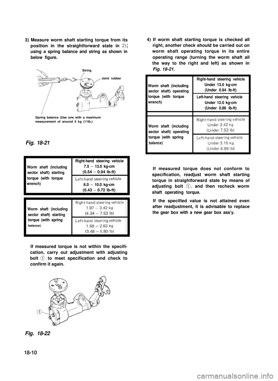
3) Measure worm shaft starting torque from its
position in the straightforward state in 2),
using a spring balance and string as shown in
below figure.
StringI
Joint rubber
Spring balance (Use one with a maximummeasurement of around 5 kg (11lb.)
Fig. 18-21
Worm shaft (including
sector shaft) starting
torque (with torque
wrench)
Right-hand steering vehicle
7.5 - 13.0 kg-cm
(0.54 - 0.94 lb-ft)
6.0 - 10.0 kg-cm
(0.43 - 0.72 lb-ft)
Right-hand steering vehicle
Worm shaft (including1.97 - 3.42 kg
sector shaft) starting(4.34 - 7.53 lb)
torque (with spring
I----
balance)-
-
If measured torque is not within the specifi-
cation, carry out adjustment with adjusting
bolt @ to meet specification and check to
confirm it again.
4) If worm shaft starting torque is checked all
right, another check should be carried out on
worm shaft operating torque in its entire
operating range (turning the worm shaft all
the way to the right and left) as shown in
Fig. 18-21.
Right-hand steering vehicle
Worm shaft (includingUnder 13.0 kg-cm
sector shaft) operating(Under 0.94 lb-ft)
torque (with torqueLeft-hand steering vehicle
wrench)Under 12.0 kg-cm
(Under 0.86 lb-ft),
Right-hand steering vehicle
Worm shaft (includingUnder 3.42 kg
sector shaft) operating(Under 7.53 lb)
torque (with spring
l-----i
balance)
6.96lb)
If measured torque does not conform to
specification, readjust worm shaft starting
torque in straightforward state by means of
adjusting bolt 0, and then recheck worm
shaft operating torque.
If the specified value is not attained even
after readjustment, it is advisable to replace
the gear box with a new gear box ass’y.
Fig. 18-22
18-10
Page 374 of 962
18-6. CHECKING STEERING COLUMN
FOR ACCIDENT DAMAGE
Cars involved in accidents resulting in body
damage or where the steering column has been
impacted may also have a damaged or misalign-
ed steering column.
Checking Procedure
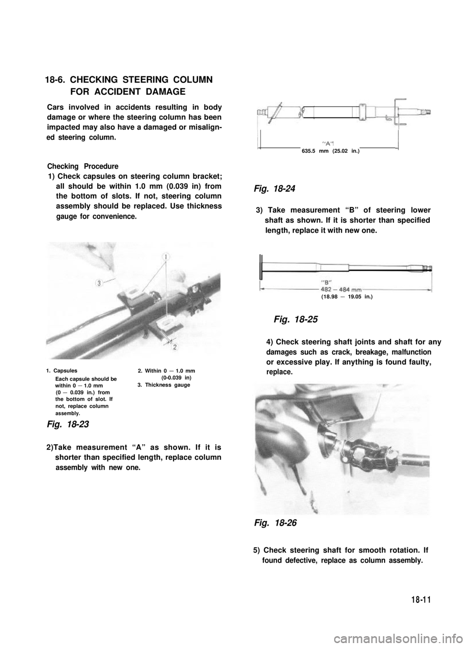
1) Check capsules on steering column bracket;
all should be within 1.0 mm (0.039 in) from
the bottom of slots. If not, steering column
assembly should be replaced. Use thickness
gauge for convenience.
1. Capsules
Each capsule should bewithin 0 - 1.0 mm(0 - 0.039 in.) fromthe bottom of slot. Ifnot, replace columnassembly.
2. Within 0 - 1.0 mm (0-0.039 in)3. Thickness gauge
Fig. 18-23
1 “A” j
635.5 mm (25.02 in.)
Fig. 18-24
3) Take measurement “B” of steering lower
shaft as shown. If it is shorter than specified
length, replace it with new one.
(18.98 - 19.05 in.)
Fig. 18-25
4) Check steering shaft joints and shaft for any
damages such as crack, breakage, malfunction
or excessive play. If anything is found faulty,
replace.
2)Take measurement “A” as shown. If it is
shorter than specified length, replace column
assembly with new one.
Fig. 18-26
5) Check steering shaft for smooth rotation. If
found defective, replace as column assembly.
18-11
Page 375 of 962
18-7. IMPORTANT STEPS IN
REINSTALLATION
NOTE:
For installation, it is important that only the
specified screws, bolts, and nuts be used as
designated and that they are tightened to the
specified torque.
Reverse removal procedure for installation,
noting the following.
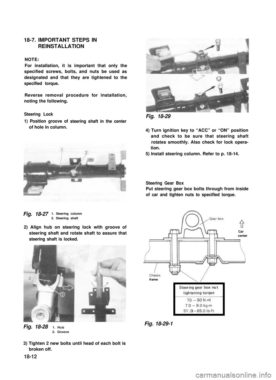
Steering Lock
1) Position groove of
of hole in column.
steering shaft in the center
Fig. 18-271. Steering column
2. Steering shaft
2) Align hub on steering lock with groove of
steering shaft and rotate shaft to assure that
steering shaft is locked.
Fig. 18-281. Hub2. Groove
Fig. 18-29
4) Turn ignition key to “ACC” or “ON” position
and check to be sure that steering shaft
rotates smoothly. Also check for lock opera-
tion.
5) Install steering column. Refer to p. 18-14.
Steering Gear Box
Put steering gear box bolts through from inside
of car and tighten nuts to specified torque.
Carcenter
frame
Steering gear box nut
tightening torque
l-----i
-N.m
-
.O -
Fig. 18-29-1
3) Tighten 2 new bolts until head of each bolt is
broken off.
18-12
Page 376 of 962
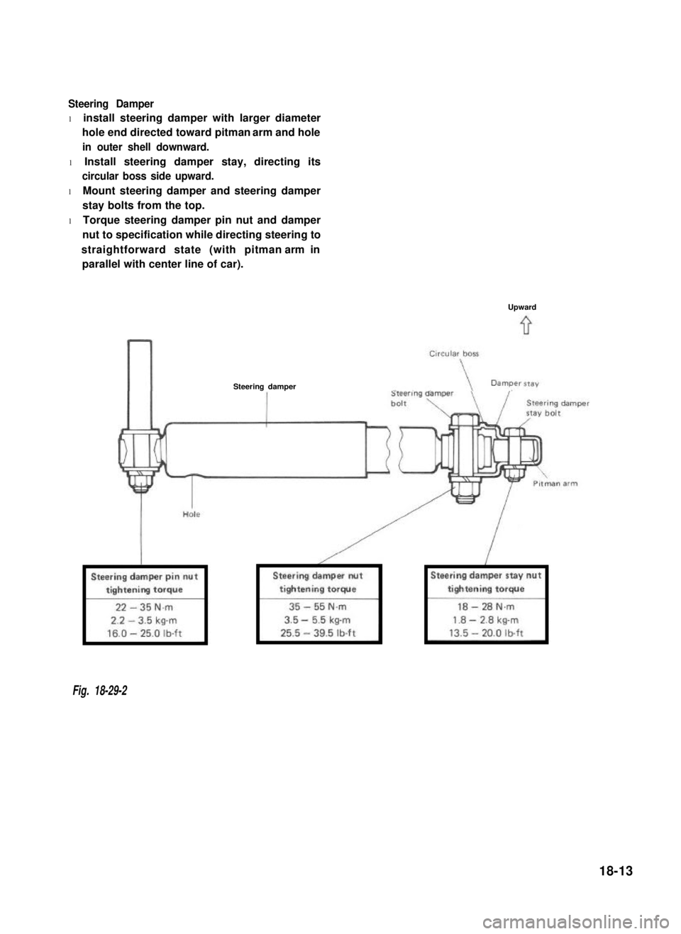
Steering Damper
l install steering damper with larger diameter
hole end directed toward pitman arm and hole
in outer shell downward.
l Install steering damper stay, directing its
circular boss side upward.
l Mount steering damper and steering damper
stay bolts from the top.
l Torque steering damper pin nut and damper
nut to specification while directing steering to
straightforward state (with pitman arm in
parallel with center line of car).
Upward
Steering damper
Fig. 18-29-2
18-13
Page 377 of 962
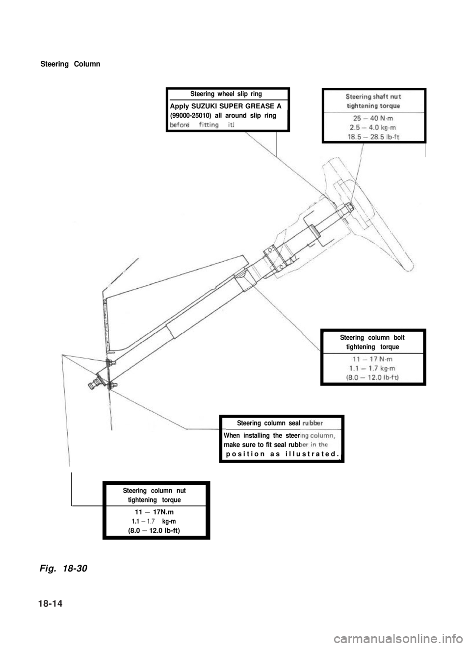
Steering Column
Steering wheel slip ring
Apply SUZUKI SUPER GREASE A
(99000-25010) all around slip ring
IIbefore fining it. , 1
Steering column seal
\I
Steering column bolt
tightening torqueI
When installing the steering column,
1.
make sure to fit seal rubber in the
rubber
1J
Steering column nut
tightening torque
11 - 17N.m
1.1 - 1.7 kg-m
(8.0 - 12.0 lb-ft)
Fig. 18-30
position as illustrated
18-14
Page 378 of 962
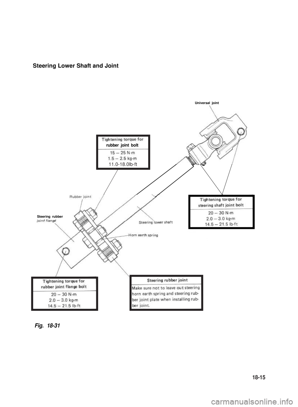
Steering Lower Shaft and Joint
Universal joint
rubber joint bolt
Steering rubberir:..,
Fig. 18-31
11.0-18.0lb-ft
18-15
Page 379 of 962
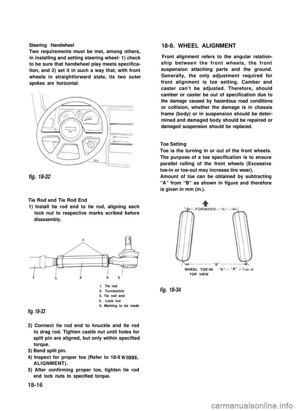
Steering Handwheel
Two requirements must be met, among others,
in installing and setting steering wheel: 1) check
to be sure that handwheel play meets specifica-
tion, and 2) set it in such a way that, with front
wheels in straightforward state, its two outer
spokes are horizontal.
fig. 18-32
Tie Rod and Tie Rod End
1) Install tie rod end to tie rod, aligning each
lock nut to respective marks scribed before
disassembly.
i25 3
1.Tie rod
2.Turnbackle3. Tie rod end
4.Lock nut5. Marking to be made
fig. 18-33
2) Connect tie rod end to knuckle and tie rod
to drag rod. Tighten castle nut until holes for
split pin are aligned, but only within specified
torque.
3) Bend split pin.
4) Inspect for proper toe (Refer to 18-8 WHEEL
ALIGNMENT).
5) After confirming proper toe, tighten tie rod
end lock nuts to specified torque.
18-8. WHEEL ALIGNMENT
Front alignment refers to the angular relation-
ship between the front wheels, the front
suspension attaching parts and the ground.
Generally, the only adjustment required for
front alignment is toe setting. Camber and
caster can’t be adjusted. Therefore, should
camber or caster be out of specification due to
the damage caused by hazardous road conditions
or collision, whether the damage is in chassis
frame (body) or in suspension should be deter-
mined and damaged body should be repaired or
damaged suspension should be replaced.
Toe Setting
Toe is the turning in or out of the front wheels.
The purpose of a toe specification is to ensure
parallel rolling of the front wheels (Excessive
toe-in or toe-out may increase tire wear).
Amount of toe can be obtained by subtracting
“A” from “B” as shown in figure and therefore
is given in mm (in.).
WHEEL TOE-IN“6” - “A” = Toe-in
TOP VIEW
fig. 18-34
18-16
Page 380 of 962
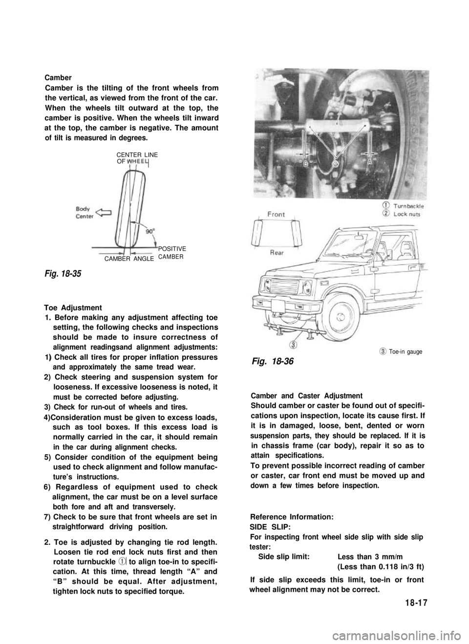
Camber
Camber is the tilting of the front wheels from
the vertical, as viewed from the front of the car.
When the wheels tilt outward at the top, the
camber is positive. When the wheels tilt inward
at the top, the camber is negative. The amount
of tilt is measured in degrees.
CENTER LINEOF yH,EEL
Fig. 18-35
CAMBER ANGLE
‘POSITIVE
CAMBER
Toe Adjustment
1. Before making any adjustment affecting toe
setting, the following checks and inspections
should be made to insure correctness of
alignment readingsand alignment adjustments:
1) Check all tires for proper inflation pressures
and approximately the same tread wear.
2) Check steering and suspension system for
looseness. If excessive looseness is noted, it
must be corrected before adjusting.
3) Check for run-out of wheels and tires.
4)Consideration must be given to excess loads,
such as tool boxes. If this excess load is
normally carried in the car, it should remain
in the car during alignment checks.
5) Consider condition of the equipment being
used to check alignment and follow manufac-
ture’s instructions.
6) Regardless of equipment used to check
alignment, the car must be on a level surface
both fore and aft and transversely.
7) Check to be sure that front wheels are set in
straightforward driving position.
2. Toe is adjusted by changing tie rod length.
Loosen tie rod end lock nuts first and then
rotate turnbuckle @ to align toe-in to specifi-
cation. At this time, thread length “A” and
“B” should be equal. After adjustment,
tighten lock nuts to specified torque.
@ Toe-in gauge
Fig. 18-36
Camber and Caster Adjustment
Should camber or caster be found out of specifi-
cations upon inspection, locate its cause first. If
it is in damaged, loose, bent, dented or worn
suspension parts, they should be replaced. If it is
in chassis frame (car body), repair it so as to
attain specifications.
To prevent possible incorrect reading of camber
or caster, car front end must be moved up and
down a few times before inspection.
Reference Information:
SIDE SLIP:
For inspecting front wheel side slip with side slip
tester:
Side slip limit:Less than 3 mm/m
(Less than 0.118 in/3 ft)
If side slip exceeds this limit, toe-in or front
wheel alignment may not be correct.
18-17