wheel size SUZUKI GRAND VITARA 1987 Service Repair Manual
[x] Cancel search | Manufacturer: SUZUKI, Model Year: 1987, Model line: GRAND VITARA, Model: SUZUKI GRAND VITARA 1987Pages: 962, PDF Size: 27.87 MB
Page 71 of 962

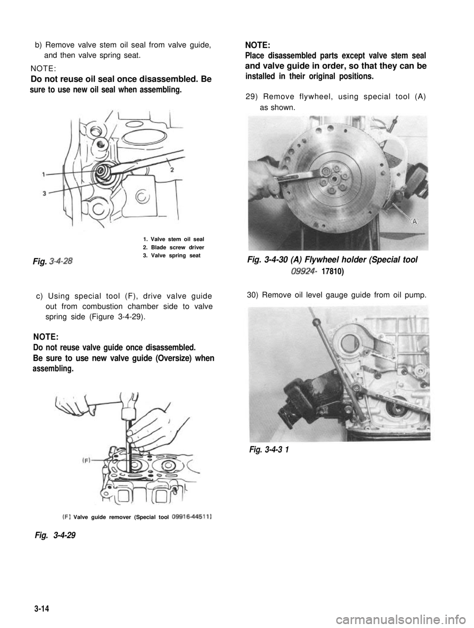
b) Remove valve stem oil seal from valve guide,
and then valve spring seat.
NOTE:
Do not reuse oil seal once disassembled. Besure to use new oil seal when assembling.
1. Valve stem oil seal
2. Blade screw driver
Fig. 3-4-283. Valve spring seat
c) Using special tool (F), drive valve guide out from combustion chamber side to valve
spring side (Figure 3-4-29).
NOTE:
Do not reuse valve guide once disassembled.
Be sure to use new valve guide (Oversize) when
assembling.
NOTE:
Place disassembled parts except valve stem seal
and valve guide in order, so that they can be
installed in their original positions.
29) Remove flywheel, using special tool (A)
as shown.
Fig. 3-4-30 (A) Flywheel holder (Special tool
09924- 17810)
30) Remove oil level gauge guide from oil pump.
Fig. 3-4-3 1 (F)
Valve guide remover (Special tool
09916-44511)
Fig. 3-4-29
3-14
Page 87 of 962

Crankshaft Main (Journal) Bearings
General informations:
l Service main bearings are available in standard-
size and 0.25 mm (0.0098 in) undersize, and
each of them has 5 kinds of bearings differ-
ing in tolerance.
l The upper half of bearing has oil groove as
indicated in Fig. 3~5-42. Install this half with
oil groove to cylinder block.
Fig. 3-5-40 Measuring thrust play of crankshaft
l Out-of-round and taper (uneven wear):
An unevenly worn crankshaft journal shows
up as a difference in diameter at a cross
section or along its length (or both). This
difference, if any, is to be determined from
micrometer readings.
If any of journals is badly damaged or if the
amount of uneven wear in the sense explained
above exceeds its limit, regrind or replace the
crankshaft.
I
Limit on out-of-round
and taper0.01 mm (0.0004 in.)
Fig. 3-5-4 1 Checking uneven wear
1. Cylinder block2. Upper half of bearing
3. Oil groove
Fig. 3-5-42 Upper half of bearing installation
l On each main bearing cap, arrow mark and
number are embossed as indicated in Fig.
3-5-43.
When installing each bearing cap to cylinder
block, point arrow mark toward crankshaft
pulley side and install each cap from crank-
shaft pulley side to flywheel side in ascending
order of numbers @,a, 0, @ and 0. Tigh-
ten cap bolts to specified torque.
3
2. Flywheel side
Fig. 3-5-43 Bearing caps ins talla tion
3-30
Page 91 of 962

Measured journal diameter
44.744 - 44.750 mm44.738 - 44.744 mm44.732 - 44.738 mm
(1.7616 - 1.7618 in.)(1.7614 - 1.7616 in.)(1.7612 - 1.7614 in.)
Alphabets stamped I AGreen & RedBlack & RedRed only
on mating surfaceBBlack & RedRed onlyYellow & Red
of cylinder blockCRed onlyYellow & RedBlue & Red
Undersize bearing to be installed.
Rear Oil Seal
Carefully inspect oil seal for wear or damage. If
its lip is worn or damaged, replace oil seal.
1. Rear oil seal
Fig. 3-5-49 Rear oil sealOil Pump
Flywheel
l If ring gear is damaged, cracked or worn,
replace flywheel.
l If surface contacting clutch disc is damaged,
or excessibly worn, replace flywheel.
l Check flywheel for face runout with a dial
wge.
If runout is out of limit, replace flywheel.
Limit on runout0.2 mm (0.0078 in.)
Fig. 3-5-50 Measuring runou t
1) Inspect oil seal lip for fault or other damage.
Replace as necessary.
2) Inspect outer and inner rotors, rotor plate,
and oil pump case for excessive wear or
damage.
l Radial clearance:
Check radial clearance between outer rotor
and case, using thickness gauge.
If clearance exceeds its limit, replace outer
rotor or case.
Outer rotor and case0.310 mm (0.0122 in.)
3-34
Page 100 of 962

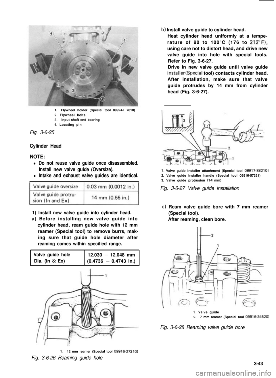
1.Flywheel holder (Special tool 09924-l 7810)
2. Flywheel bolts
3.Input shaft end bearing
4. Locating pin
Fig. 3-6-25
Cylinder Head
NOTE:
l Do not reuse valve guide once disassembled.
Install new valve guide (Oversize).
l Intake and exhaust valve guides are identical.
1) Install new valve guide into cylinder head.
a) Before installing new valve guide into
cylinder head, ream guide hole with 12 mm
reamer (Special tool) to remove burrs, mak-
ing sure that guide hole diameter after
reaming comes within specified range.
Valve guide hole12.030 - 12.048 mm
Dia. (In & Ex)(0.4736 - 0.4743 in.)
b) Install valve guide to cylinder head.
Heat cylinder head uniformly at a tempe-
rature of 80 to 100°C (176 to 212”F),
using care not to distort head, and drive new
valve guide into hole with special tools.
Refer to Fig. 3-6-27.
Drive in new valve guide until valve guide
installer(Special tool) contacts cylinder head.
After installation, make sure that valve
guide protrudes by 14 mm from cylinder
head (Fig. 3-6-27).
1. Valve guide installer attachment (Special tool 09917-88210)
2. Valve guide installer handle (Special tool 09916-57321)
3. Valve guide protrusion (14 mm)
Fig. 3-6-27 Valve guide installation
clReam valve guide bore with 7 mm reamer
(Special tool).
After reaming, clean bore.
1. Valve guide
2.7 mm reamer (Special tool 09916-34520)
Fig. 3-6-28 Reaming valve guide bore
1.12 mm reamer (Special tool 09916-37310)
Fig. 3-6-26 Reaming guide hole
3-43
Page 357 of 962

Before giving a test pull to knuckle arm with a
spring balance in the alternative method, in-
stall a large amount of shims on each kingpin to
lighten preload on tapered roller bearing.
Keep on reading the torque, each time decreas-
ing shim thickness a little, and continue this
process until specified torque value is obtained.
(This process protects kingpins because it ensure
that no excessive pull will be applied to bearings
at the onset.) If the process fails to produce
specified torque, that is, if desired torque
resistance does not occur even when shim
thickness has been reduced to zero on each
kingpin, it means that bearings or kingpins are
excessively worn and need replacement.
NOTE:
l Read spring balance indication when knuckle
arm begins to turn. In other words, you are
to read “starting torque.”
l When checking knuckle arm starting torque,
be sure to have axle hub oil seal removed
and tighten king pin bolts to specified torque.
Knuckle arm starting1 .O - 1.8 kg (2.20 - 3.96 lb)
torque (force)without oil seal
Available sizes of0.1,0.5 mm
shim for kingpins(0.004,0.02 in.)
/r--QzL- -\King pin shim
Fig. 17-3-13
Upon completion of this check and/or adjust-
ment, be sure to connect tie rod end to steering
knuckle and install oil seal retainer, oil seal,
felt packing oil seal cover and wheel.
Refer to “INSTALLATION” in this section.
Steering Knuckle Oil Seal
The oil seal used at the spherical sliding joint
between knuckle and inner case accomplishes
additional purposes of keeping out road dust
and of acting as the damper for steering hand-
wheel. As wear of this seal advances, its damping
effect decreases and thus makes front wheel
develop a tendency to “shimmy” not onI9 that
road dust begins to creep into sliding clearance
to promote wear of spherical sliding surfaces.
The oil seal is an expendable item, and must be
replaced at regular intervals.
Fig. 17-3-14
[How to replace oil seal]
1) Remove 8 bolts securing joint seat, and
displace oil seal cover and felt packing inward.
Fig. 17-3-15
17-23
Page 382 of 962

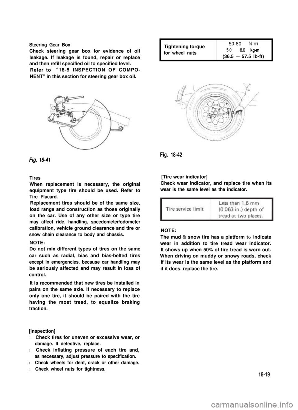
Steering Gear Box
Check steering gear box for evidence of oil
leakage. If leakage is found, repair or replace
and then refill specified oil to specified level.
Refer to“18-5 INSPECTION OF COMPO-
NENT” in this section for steering gear box oil.
Tightening torque
for wheel nuts
50-80 N.m
5.0 - 8.0 kg-m
(36.5 - 57.5 lb-ft)
Fig. 18-42
Fig. 18-41
Tires[Tire wear indicator]
When replacement is necessary, the original
equipment type tire should be used. Refer to
Tire Placard.
Check wear indicator, and replace tire when its
wear is the same level as the indicator.
Replacement tires should be of the same size,
load range and construction as those originally
on the car. Use of any other size or type tire
may affect ride, handling, speedometer/odometer
calibration, vehicle ground clearance and tire or
snow chain clearance to body and chassis.
NOTE:
NOTE:
Do not mix different types of tires on the same
car such as radial, bias and bias-belted tires
except in emergencies, because car handling may
be seriously affected and may result in loss of
control.
The mud & snow tire has a platform ttr indicate
wear in addition to tire tread wear indicator.
It shows up when 50% of tire tread is worn out.
When driving on muddy or snowy roads, check
if its wear is the same level as the platform and
if it does, replace the tire.
It is recommended that new tires be installed in
pairs on the same axle. If necessary to replace
only one tire, it should be paired with the tire
having the most tread, to equalize braking
traction.
[Inspection]
l Check tires for uneven or excessive wear, or
damage. If defective, replace.
l Check inflating pressure of each tire and,
as necessary, adjust pressure to specification.
l Check wheels for dent, crack or other damage.
l Check wheel nuts for tightness.
18-19
Page 383 of 962
![SUZUKI GRAND VITARA 1987 Service Repair Manual Fig. 18-43 @ Tire tread wear indicator
@ Wear indicating platform
[ Inflation of tires]
l Tire inflation pressures are listed on the
Tire Placard at driver’s side of instrument
panel.
l Tire inflati SUZUKI GRAND VITARA 1987 Service Repair Manual Fig. 18-43 @ Tire tread wear indicator
@ Wear indicating platform
[ Inflation of tires]
l Tire inflation pressures are listed on the
Tire Placard at driver’s side of instrument
panel.
l Tire inflati](/img/20/57437/w960_57437-382.png)
Fig. 18-43 @ Tire tread wear indicator
@ Wear indicating platform
[ Inflation of tires]
l Tire inflation pressures are listed on the
Tire Placard at driver’s side of instrument
panel.
l Tire inflation pressures should be checked
(including spare tire) at least monthly and
when significantly changing the load in the
car.
l Always check tire inflation pressures when
tires are “cold”.
l Always use tire pressure gauge when checking
inflation pressure.
l Be sure to reinstall tire inflation valve caps to
prevent dirt and moisture from getting into
valve core, as they may cause air leakage.
l If air loss occurs while driving, do not drive
on the deflated tire more than is needed to
stop safety. Driving even a short distance on a
deflated tire can damage a tire and wheel
beyond repair.
NOTE:
Before installing wheels, remove any build-up of
corrosion on the wheel mounting surface and
brake drum or disc mounting surface by scraping
and wire brushing. Installing wheels without
good metal-to-metal contact at the mounting
surfaces can cause wheel nuts to loosen, which
can later allow a wheel to come off while the
car is moving.
RADIAL TIRES
.i II
9T
\
I
4-wheels
Fig. 18-44
fT
u
[I
5-wheels
[Wheels]
Wheels must be replaced if they are bent, dented,
have excessive lateral or radial runout, leak air
through welds, have elongated bolt holes, if
lug nuts won’t stay tight, or if they are heavily
rusted. Wheels with greater runout than shown
in below figure may cause objectional vibrations.
Replacement wheels must be equivalent to the
original equipment wheels in load capacity,
diameter,rim width, offset and mounting
configuration. A wheel of improper size or type
may affect wheel and bearing life, brake cooling,
speedometer/odometer calibration, car ground
clearance and tire clearance to the body and
chassis.
[Tire rotation]
“Rotate” tires at the regular intervals in order to
equalize tire wear and thereby make full use of
each tire. Refer to below figure for the scheme
of rotation. Adherence to this scheme prolongs
tire life.
18-20
Page 472 of 962

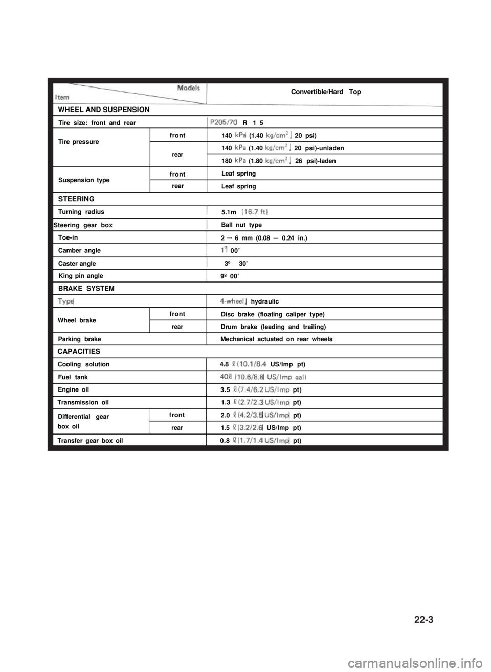
Convertible/Hard Top
WHEEL AND SUSPENSIONI
Tire size: front and rear1 P205/70 R15I
Tire pressurefront
rear
Suspension typefront
rear
140 kPa (1.40 kg/cm’, 20 psi)
140 kPa (1.40 kg/cm’, 20 psi)-unladen
180 kPa (1.80 kg/cm*, 26 psi)-laden
Leaf spring
Leaf spring
STEERING
Turning radius1 5.1 m (16.7ft)
1 Steering gear box1Ball nut typeI
Toe-in
Camber angle
Caster angle
King pin angle
BRAKE SYSTEM
Type
Wheel brake
Parking brake
CAPACITIES
Cooling solution
Fuel tank
2 - 6 mm (0.08 - 0.24 in.)
lo 00’
) 3º 30’I
front
rear
9º 00’
4-wheel, hydraulic
Disc brake (floating caliper type)
Drum brake (leading and trailing)
Mechanical actuated on rear wheels
4.8 Q (10.1/8.4 US/Imp pt)
4OQ (10.6/8.8 US/Imp cral)
Engine oil
Transmission oil
Differential gear
box oil
Transfer gear box oil
front
rear
3.5 II (7.4/6.2 US/Imp pt)
1.3 II (2.7/2.3 US/Imp pt)
2.0 Q (4.2/3.5 US/Imp pt)
1.5 II (3.2/2.6 US/Imp pt)
0.8 !? (1.7/l .4 US/Imp pt)
22-3