remove SUZUKI GRAND VITARA 2022 Owners Manual
[x] Cancel search | Manufacturer: SUZUKI, Model Year: 2022, Model line: GRAND VITARA, Model: SUZUKI GRAND VITARA 2022Pages: 482, PDF Size: 21 MB
Page 5 of 482
54P00-01E
RECOMMENDATION OF GENUINE SUZUKI PARTS AND ACCESSORIES USE
SUZUKI strongly recommends the use of genuine SUZUKI parts* and accessories. Genuine SUZUKI parts and accessories are built to
the highest standards of quality and performance, and are designed to fit your vehicle’s exact specifications.
A wide variety of non-genuine replacement parts and accessories for SUZUKI vehicles are currently available in the market. Using these
parts and accessories can affect the vehicle performance and shorten its useful life. Therefore, installation of non-genuine SUZUKI parts
and accessories is not covered under warranty.
Non-genuine SUZUKI parts and accessoriesSome parts and accessories may be approved by certain authorities in your country.
Some parts and accessories are sold as SUZUKI-authorized replacement parts and accessories. Some genuine SUZUKI parts and
accessories are sold as re-use parts and accessories. These parts and accessories are non-genuine SUZUKI parts and accessories and
use of these parts is not covered under warranty.
Re-use of genuine SUZUKI parts and accessoriesThe resale or re-use of the following items which could cause hazards for users is expressly forbidden:
• Air bag components and all other pyrotechnic items, including their components (e.g. cushion, control devices and sensors)
• Seat belt system, including their components (e.g. webbing, buckles and retractors)
The air bag and seat belt pretensioner components contain explosive chemicals. These components should be removed and disposed
of properly by SUZUKI-authorized service shop or scrap yard to avoid unintended explosion before scrapping.
*The parts remanufactured under SUZUKI’s approval can be used as genuine SUZUKI parts in Europe.
Page 24 of 482
2-2
BEFORE DRIVING
54P00-01E
The immobilizer/keyless push start system
warning light may also blinks if the remote
controller is not in the vehicle when you
close the door or attempt to start the
engine.
NOTE:
• If you lose your immobilizer ignition key
or remote controller, ask your SUZUKI
dealer as soon as possible to deactivate
the lost one, and to make a new key or
remote controller.
• If you own other vehicles with immobi-
lizer keys, keep those keys away from
the ignition switch or the engine switch
when using your SUZUKI vehicle. Other-
wise, or the engine may not be started
because they may interfere with your
SUZUKI vehicle’s immobilizer system.
• If you attach any metal objects to the
immobilizer key or remote controller, it
may not start the engine.This immobilizer system, model I54P0 for
keyless entry model and 37290-54P0 for
keyless engine start model are in compli-
ance with the essential requirements and
other provisions of Directive 1999/5/EC.
Ignition key reminder (if equipped)
A buzzer sounds intermittently to remind
you to remove the ignition key if it is in the
ignition switch when the driver’s door is
opened.
Door locks
Side door locks
60B008
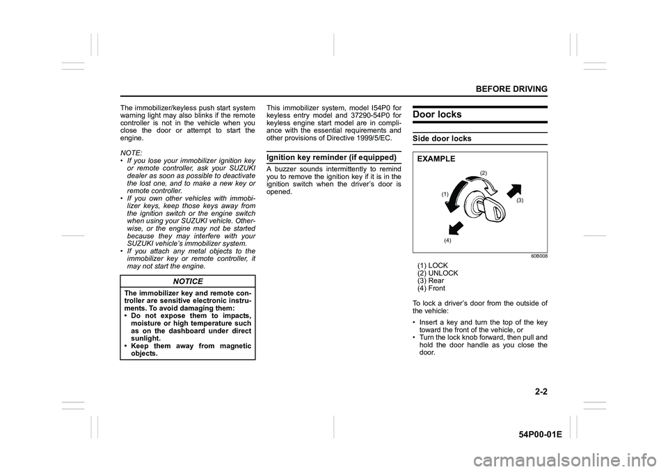
(1) LOCK
(2) UNLOCK
(3) Rear
(4) Front
To lock a driver’s door from the outside of
the vehicle:
• Insert a key and turn the top of the key
toward the front of the vehicle, or
• Turn the lock knob forward, then pull and
hold the door handle as you close the
door.
NOTICE
The immobilizer key and remote con-
troller are sensitive electronic instru-
ments. To avoid damaging them:
• Do not expose them to impacts,
moisture or high temperature such
as on the dashboard under direct
sunlight.
• Keep them away from magnetic
objects.
(2)
(1)
(3)
(4)
EXAMPLE
Page 32 of 482
2-10
BEFORE DRIVING
54P00-01E
NOTE:
The keyless push start system may not
function correctly in certain environments
or under certain operating conditions such
as the following:
• When there are strong signals coming
from a television, power station or a cel-
lular phone.
• When the remote controller is in contact
with or covered by a metal object.
• When a radio wave type remote keyless
entry is used nearby.
• When the remote controller is placed
near an electronic device such as per-
sonal computer.
Some additional precautions you should
take and information you should be aware
of are:
• Check that the key is stowed in the
remote controller. If the remote controller
becomes unreliable, you will not be able
to lock or unlock the doors.• Check that the driver always carries the
remote controller.
• If you lose one of the remote controllers,
ask your SUZUKI dealer as soon as pos-
sible for a replacement. Have your
dealer program the new remote control-
ler code in your vehicle’s memory so that
the old code is erased.
• You can use up to four remote control-
lers and the keys for your vehicle. Ask
your SUZUKI dealer for details.
• The battery life of the remote controller
is about two years, but it can vary
depending on usage conditions.
57L21016
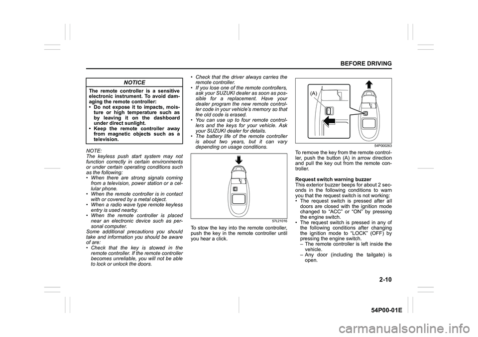
To stow the key into the remote controller,
push the key in the remote controller until
you hear a click.
54P000263
To remove the key from the remote control-
ler, push the button (A) in arrow direction
and pull the key out from the remote con-
troller.
Request switch warning buzzer
This exterior buzzer beeps for about 2 sec-
onds in the following conditions to warn
you that the request switch is not working:
• The request switch is pressed after all
doors are closed with the ignition mode
changed to “ACC” or “ON” by pressing
the engine switch.
• The request switch is pressed in any of
the following conditions after changing
the ignition mode to “LOCK” (OFF) by
pressing the engine switch.
– The remote controller is left inside the
vehicle.
– Any door (including the tailgate) is
open.
NOTICE
The remote controller is a sensitive
electronic instrument. To avoid dam-
aging the remote controller:
• Do not expose it to impacts, mois-
ture or high temperature such as
by leaving it on the dashboard
under direct sunlight.
• Keep the remote controller away
from magnetic objects such as a
television.(A)
Page 36 of 482
2-14
BEFORE DRIVING
54P00-01E
NOTE:
You can switch the function that unlocks all
doors from requiring two pushes to requir-
ing one push, and vice versa, via the infor-
mation display setting mode. For details on
how to use the information display, refer to
“Information display” in this section.
The turn signal lights will flash once when
the doors are locked and then the turn sig-
nal lights will flash once again when the
doors are locked with the dead lock sys-
tem.
When the doors are unlocked:
• The turn signal lights will flash twice.
• If the interior light switch is in DOOR
position, the interior light will turn on for
about 15 seconds and then fade out. If
you insert the key into the ignition switch
during this time, the light will start to fade
out immediately.
Check that the doors are locked after you
operate LOCK button (1).
NOTE:
If no door is opened within about 30 sec-
onds after UNLOCK button (2) is operated,
the doors will automatically lock again.NOTE:
• The maximum operating distance of the
keyless entry system transmitter is about
5 m (16 ft.), but this can vary depending
on the surroundings, especially near
other transmitting devices such as radio
towers or CB (Citizen’s Band) radios.
• The door locks cannot be operated with
the transmitter, if the ignition key is
inserted in the ignition switch.
• When any door is open, the door locks
can only be unlocked with the transmit-
ter, and the turn signal light will not flash.
• If you lose one of the transmitters, ask
your SUZUKI dealer as soon as possible
for a replacement. Have your dealer pro-
gram the new transmitter code in your
vehicle’s memory so that the old code is
erased.Battery replacement
If the transmitter becomes unreliable,
replace the battery.
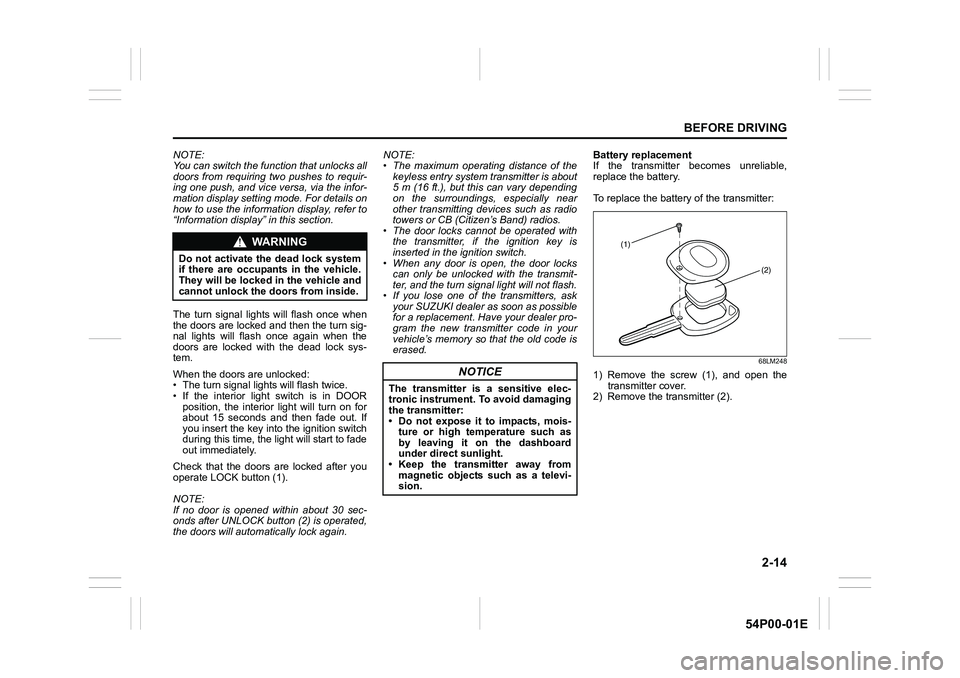
To replace the battery of the transmitter:
68LM248
1) Remove the screw (1), and open the
transmitter cover.
2) Remove the transmitter (2).
WA R N I N G
Do not activate the dead lock system
if there are occupants in the vehicle.
They will be locked in the vehicle and
cannot unlock the doors from inside.
NOTICE
The transmitter is a sensitive elec-
tronic instrument. To avoid damaging
the transmitter:
• Do not expose it to impacts, mois-
ture or high temperature such as
by leaving it on the dashboard
under direct sunlight.
• Keep the transmitter away from
magnetic objects such as a televi-
sion.
(1)
(2)
Page 40 of 482
2-18
BEFORE DRIVING
54P00-01E
81A009
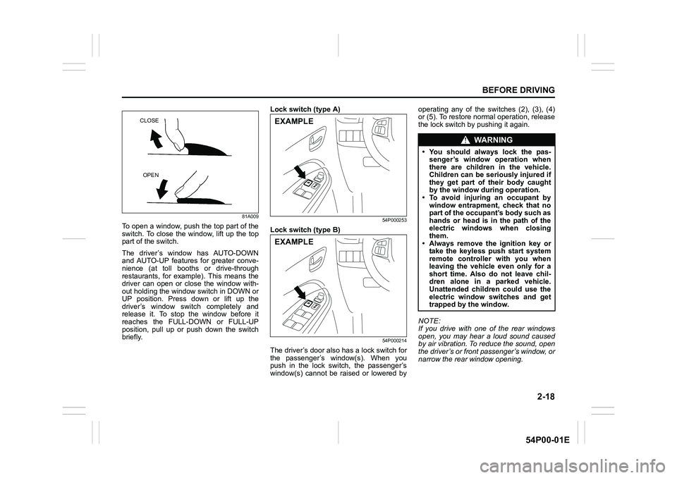
To open a window, push the top part of the
switch. To close the window, lift up the top
part of the switch.
The driver’s window has AUTO-DOWN
and AUTO-UP features for greater conve-
nience (at toll booths or drive-through
restaurants, for example). This means the
driver can open or close the window with-
out holding the window switch in DOWN or
UP position. Press down or lift up the
driver’s window switch completely and
release it. To stop the window before it
reaches the FULL-DOWN or FULL-UP
position, pull up or push down the switch
briefly.Lock switch (type A)54P000253
Lock switch (type B)
54P000214
The driver’s door also has a lock switch for
the passenger’s window(s). When you
push in the lock switch, the passenger’s
window(s) cannot be raised or lowered byoperating any of the switches (2), (3), (4)
or (5). To restore normal operation, release
the lock switch by pushing it again.
NOTE:
If you drive with one of the rear windows
open, you may hear a loud sound caused
by air vibration. To reduce the sound, open
the driver’s or front passenger’s window, or
narrow the rear window opening.
CLOSE
OPENEXAMPLE
EXAMPLE
WA R N I N G
• You should always lock the pas-
senger’s window operation when
there are children in the vehicle.
Children can be seriously injured if
they get part of their body caught
by the window during operation.
• To avoid injuring an occupant by
window entrapment, check that no
part of the occupant’s body such as
hands or head is in the path of the
electric windows when closing
them.
• Always remove the ignition key or
take the keyless push start system
remote controller with you when
leaving the vehicle even only for a
short time. Also do not leave chil-
dren alone in a parked vehicle.
Unattended children could use the
electric window switches and get
trapped by the window.
Page 45 of 482
2-23
BEFORE DRIVING
54P00-01E
Head restraints
80J001
Head restraints are designed to help
reduce the risk of neck injuries in the case
of an accident. Adjust the head restraint to
the position which places the center of the
head restraint closest to the top of your
ears. If this is not possible for very tall pas-
sengers, adjust the head restraint as high
as possible.NOTE:
It may be necessary to recline the seat-
back to provide enough overhead clear-
ance to remove the head restraint.
Front
61MM0A032
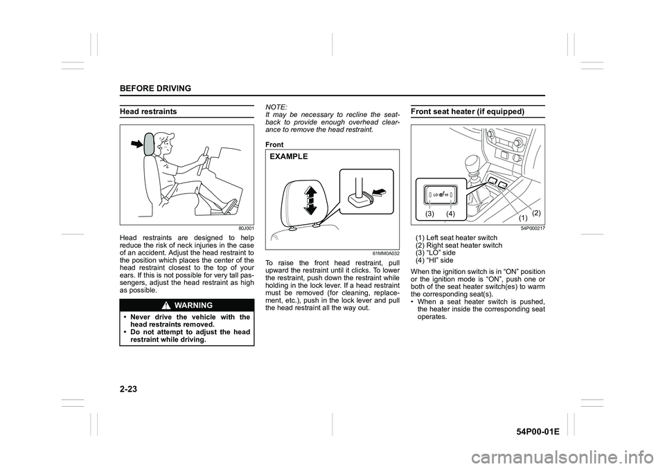
To raise the front head restraint, pull
upward the restraint until it clicks. To lower
the restraint, push down the restraint while
holding in the lock lever. If a head restraint
must be removed (for cleaning, replace-
ment, etc.), push in the lock lever and pull
the head restraint all the way out.
Front seat heater (if equipped)
54P000217
(1) Left seat heater switch
(2) Right seat heater switch
(3) “LO” side
(4) “HI” side
When the ignition switch is in “ON” position
or the ignition mode is “ON”, push one or
both of the seat heater switch(es) to warm
the corresponding seat(s).
• When a seat heater switch is pushed,
the heater inside the corresponding seat
operates.
WA R N I N G
• Never drive the vehicle with the
head restraints removed.
• Do not attempt to adjust the head
restraint while driving.
EXAMPLE
(3) (4)(1)(2)
Page 48 of 482
2-26
BEFORE DRIVING
54P00-01E
Head restraints
Head restraints are designed to help
reduce the risk of neck injuries in the case
of an accident.
NOTE:
It may be necessary to fold forward the
seatback to provide enough overhead
clearance to remove the head restraint.
Adjust the head restraint to the position
which places the center of the head
restraint closest to the top of your ears. If
this is not possible for very tall passengers,
adjust the head restraint as high as possi-
ble.Rear
61MM0A033
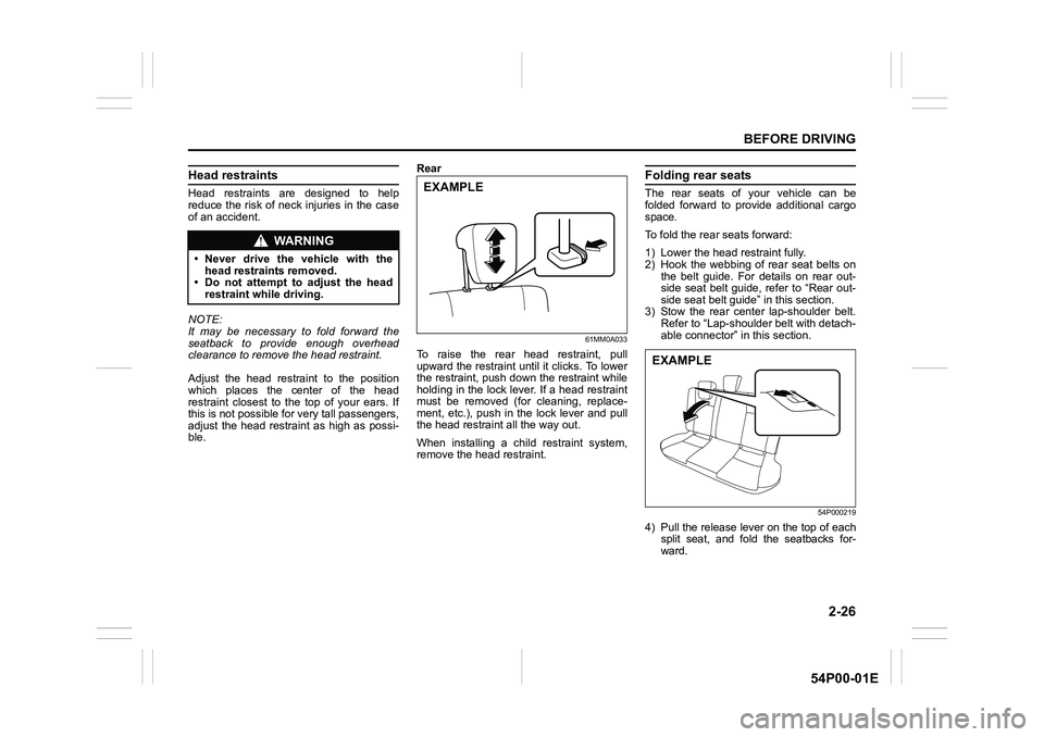
To raise the rear head restraint, pull
upward the restraint until it clicks. To lower
the restraint, push down the restraint while
holding in the lock lever. If a head restraint
must be removed (for cleaning, replace-
ment, etc.), push in the lock lever and pull
the head restraint all the way out.
When installing a child restraint system,
remove the head restraint.
Folding rear seats
The rear seats of your vehicle can be
folded forward to provide additional cargo
space.
To fold the rear seats forward:
1) Lower the head restraint fully.
2) Hook the webbing of rear seat belts on
the belt guide. For details on rear out-
side seat belt guide, refer to “Rear out-
side seat belt guide” in this section.
3) Stow the rear center lap-shoulder belt.
Refer to “Lap-shoulder belt with detach-
able connector” in this section.
54P000219
4) Pull the release lever on the top of each
split seat, and fold the seatbacks for-
ward.
WA R N I N G
• Never drive the vehicle with the
head restraints removed.
• Do not attempt to adjust the head
restraint while driving.
EXAMPLE
EXAMPLE
Page 65 of 482
2-43
BEFORE DRIVING
54P00-01E
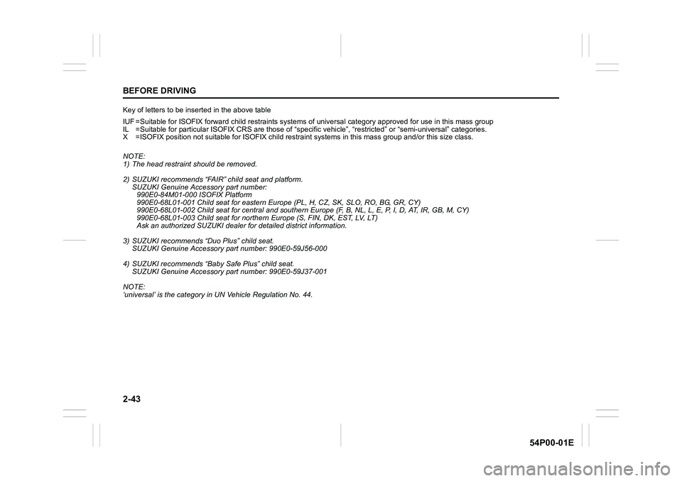
Key of letters to be inserted in the above table
IUF =Suitable for ISOFIX forward child restraints systems of universal category approved for use in this mass group
IL =Suitable for particular ISOFIX CRS are those of “specific vehicle”, “restricted” or “semi-universal” categories.
X =ISOFIX position not suitable for ISOFIX child restraint systems in this mass group and/or this size class.
NOTE:
1) The head restraint should be removed.
2) SUZUKI recommends “FAIR” child seat and platform.
SUZUKI Genuine Accessory part number:
990E0-84M01-000 ISOFIX Platform
990E0-68L01-001 Child seat for eastern Europe (PL, H, CZ, SK, SLO, RO, BG, GR, CY)
990E0-68L01-002 Child seat for central and southern Europe (F, B, NL, L, E, P, I, D, AT, IR, GB, M, CY)
990E0-68L01-003 Child seat for northern Europe (S, FIN, DK, EST, LV, LT)
Ask an authorized SUZUKI dealer for detailed district information.
3) SUZUKI recommends “Duo Plus” child seat.
SUZUKI Genuine Accessory part number: 990E0-59J56-000
4) SUZUKI recommends “Baby Safe Plus” child seat.
SUZUKI Genuine Accessory part number: 990E0-59J37-001
NOTE:
‘universal’ is the category in UN Vehicle Regulation No. 44.
Page 67 of 482
2-45
BEFORE DRIVING
54P00-01E
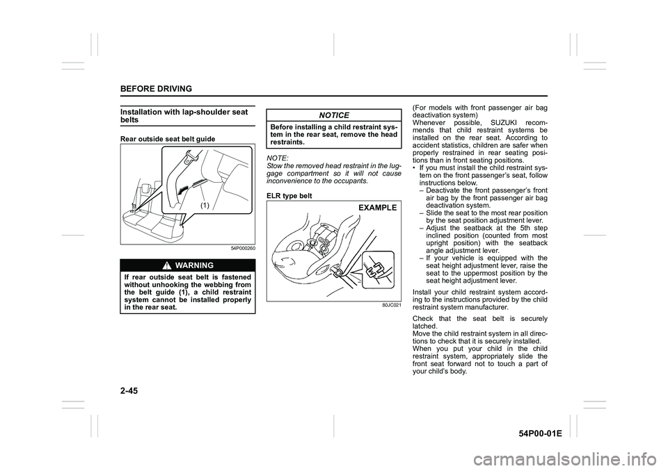
Installation with lap-shoulder seat belts
Rear outside seat belt guide
54P000260
NOTE:
Stow the removed head restraint in the lug-
gage compartment so it will not cause
inconvenience to the occupants.
ELR type belt
80JC021
(For models with front passenger air bag
deactivation system)
Whenever possible, SUZUKI recom-
mends that child restraint systems be
installed on the rear seat. According to
accident statistics, children are safer when
properly restrained in rear seating posi-
tions than in front seating positions.
• If you must install the child restraint sys-
tem on the front passenger’s seat, follow
instructions below.
– Deactivate the front passenger’s front
air bag by the front passenger air bag
deactivation system.
– Slide the seat to the most rear position
by the seat position adjustment lever.
– Adjust the seatback at the 5th step
inclined position (counted from most
upright position) with the seatback
angle adjustment lever.
– If your vehicle is equipped with the
seat height adjustment lever, raise the
seat to the uppermost position by the
seat height adjustment lever.
Install your child restraint system accord-
ing to the instructions provided by the child
restraint system manufacturer.
Check that the seat belt is securely
latched.
Move the child restraint system in all direc-
tions to check that it is securely installed.
When you put your child in the child
restraint system, appropriately slide the
front seat forward not to touch a part of
your child’s body.
WA R N I N G
If rear outside seat belt is fastened
without unhooking the webbing from
the belt guide (1), a child restraint
system cannot be installed properly
in the rear seat.
(1)
NOTICE
Before installing a child restraint sys-
tem in the rear seat, remove the head
restraints.
EXAMPLE
Page 68 of 482
2-46
BEFORE DRIVING
54P00-01E
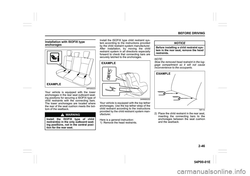
Installation with ISOFIX type anchorages
54P000223
Your vehicle is equipped with the lower
anchorages in the rear seat outboard seat-
ing positions for securing a ISOFIX type of
child restraints with the connecting bars.
The lower anchorages are located where
the rear of the seat cushion meets the bot-
tom of the seatback.Install the ISOFIX type child restraint sys-
tem according to the instructions provided
by the child restraint system manufacturer.
After installation, try moving the child
restraint system in all directions especially
forward to check that connecting bars are
securely latched to the anchorages.
84MM00252
Your vehicle is equipped with the top tether
anchorages. Use the top tether strap of the
child restraint according to the instructions
provided by the child restraint system man-
ufacturer.
Here is a general instruction:
1) Remove the head restraints.NOTE:
Stow the removed head restraint in the lug-
gage compartment so it will not cause
inconvenience to the occupants.
78F114
2) Place the child restraint in the rear seat,
inserting the connecting bars to the
anchorages between the seat cushion
and the seatback.WA R N I N G
Install the ISOFIX type of child
restraint(s) in the only outboard seat-
ing positions, not in the central posi-
tion for the rear seat.
EXAMPLE
EXAMPLE
NOTICE
Before installing a child restraint sys-
tem in the rear seat, remove the head
restraints.
EXAMPLE