SUZUKI GRAND VITARA 2022 Owners Manual
Manufacturer: SUZUKI, Model Year: 2022, Model line: GRAND VITARA, Model: SUZUKI GRAND VITARA 2022Pages: 482, PDF Size: 21 MB
Page 261 of 482
5-19
OTHER CONTROLS AND EQUIPMENT
54P00-01E
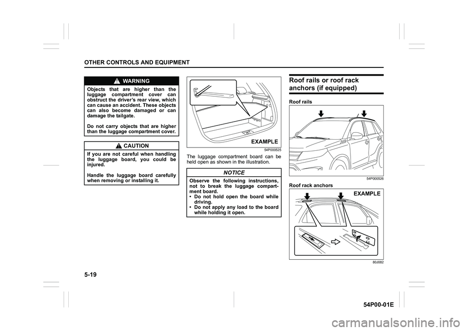
54P000525
The luggage compartment board can be
held open as shown in the illustration.
Roof rails or roof rack
anchors (if equipped)
Roof rails
54P000526
Roof rack anchors
80J082
WA R N I N G
Objects that are higher than the
luggage compartment cover can
obstruct the driver’s rear view, which
can cause an accident. These objects
can also become damaged or can
damage the tailgate.
Do not carry objects that are higher
than the luggage compartment cover.
CAUTION
If you are not careful when handling
the luggage board, you could be
injured.
Handle the luggage board carefully
when removing or installing it.
NOTICE
Observe the following instructions,
not to break the luggage compart-
ment board.
• Do not hold open the board while
driving.
• Do not apply any load to the board
while holding it open.
EXAMPLE
EXAMPLE
Page 262 of 482
5-20
OTHER CONTROLS AND EQUIPMENT
54P00-01E
You can use the roof rails or the roof rack
anchors to attach the optional roof rack
which is available at your SUZUKI dealer.
If you use a roof rack, observe the instruc-
tions and precautions in this section and
provided with the roof rack.
• Check that the roof rack is securely
installed.
• To mount various types of cargo (such
as skis, bicycles, etc.) properly, use suit-
able attachments which are available at
your SUZUKI dealer. Install the attach-
ments properly and securely according
to the instructions provided. Do not
mount cargo directly on the roof panel.
The cargo can damage the roof panel.
• The gross weight of the roof rack plus
cargo must not exceed the loading
capacity.
– Roof rails: 75 kg (165 lbs)
– Roof rack anchors: 50 kg (110 lbs)
Also, do not let the gross vehicle weight
(fully loaded vehicle including driver,
passengers, cargo, roof load and trailer
tongue weight) exceed the Gross Vehi-
cle Weight Rating (GVWR) listed in
“SPECIFICATIONS” section.
• Mount and secure the cargo onto the
roof rack properly according to the
instructions provided. Stow the heaviest
items at the bottom and distribute the
cargo as evenly as possible.
• Do not carry large items that hang over
the bumpers or the sides of the vehicle.Otherwise, these items could block your
view.
• Secure the front and rear ends of long
items such as wood panels and surf-
boards, to both the front and rear of the
vehicle. You should protect the painted
surfaces of the vehicle from scuffing
caused by tie-down ropes.
• Check periodically that the roof rack is
securely installed and free from damage.
• For vehicles with roof rack anchors,
check that the anchors are covered with
the caps when not in use.Frame hooks
Your SUZUKI not recommend you use the
frame hooks for towing another vehicle.
SUZUKI was originally designed to tow
your vehicle on the road emergency tow-
ing.
If your vehicle needs to be towed in an
emergency, refer to “Towing” in “EMER-
GENCY SERVICE” section.
WA R N I N G
• Abrupt maneuvers or failure to
properly secure cargo can allow
the cargo to fly off the vehicle and
hit others, causing personal injury
or property damage.
• Mount cargo securely and avoid
abrupt maneuvers such as jackrab-
bit starts, sharp turns, fast corner-
ing and sudden braking. Check
periodically that cargo is securely
fastened.
• Large, bulky, long or flat items can
affect vehicle aerodynamics or be
caught by the wind, and can reduce
vehicle control resulting in an acci-
dent and personal injury. Drive cau-
tiously at a safely reduced speed
when carrying this type of cargo.
WA R N I N G
Observe the following instructions
when using frame hooks. The towing
hook or vehicle body may break and
cause serious injury or damage.
• Do not use the frame hooks for
towing another vehicle.
• Avoid pulling the vehicle to get out
of severe snowy, muddy or sandy
conditions, sudden starts or erratic
driving maneuvers which could
cause excessive stress on the tow-
ing hook.
In such case, we recommend that
you contact a professional service.
Page 263 of 482
5-21
OTHER CONTROLS AND EQUIPMENT
54P00-01E
Front
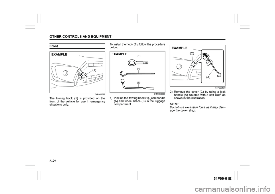
54P000527
The towing hook (1) is provided on the
front of the vehicle for use in emergency
situations only.To install the hook (1), follow the procedure
below.
61MM0B039
1) Pick up the towing hook (1), jack handle
(A) and wheel brace (B) in the luggage
compartment.
54P000528
2) Remove the cover (C) by using a jack
handle (A) covered with a soft cloth as
shown in the illustration.
NOTE:
Do not use excessive force as it may dam-
age the cover strap.
(1)
EXAMPLE(1)
(A)
(B)
EXAMPLE
(A)
(C)
EXAMPLE
Page 264 of 482
5-22
OTHER CONTROLS AND EQUIPMENT
54P00-01E
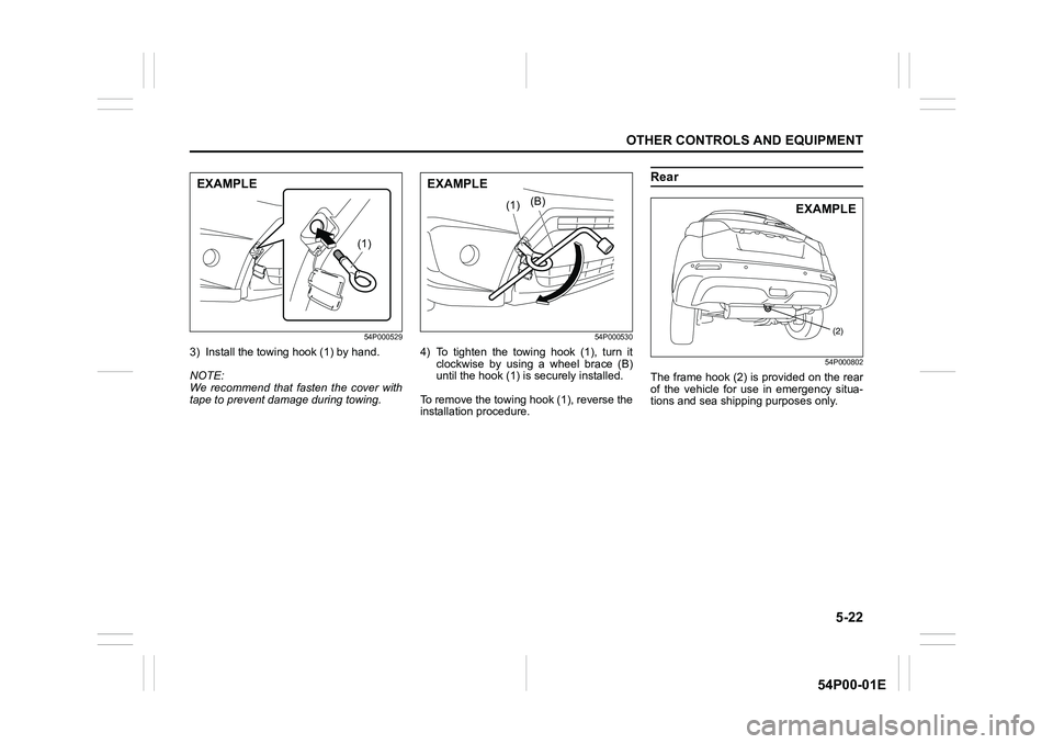
54P000529
3) Install the towing hook (1) by hand.
NOTE:
We recommend that fasten the cover with
tape to prevent damage during towing.
54P000530
4) To tighten the towing hook (1), turn it
clockwise by using a wheel brace (B)
until the hook (1) is securely installed.
To remove the towing hook (1), reverse the
installation procedure.
Rear
54P000802
The frame hook (2) is provided on the rear
of the vehicle for use in emergency situa-
tions and sea shipping purposes only.
(1)
EXAMPLE
(B)(1)
EXAMPLE
(2)
EXAMPLE
Page 265 of 482
5-23
OTHER CONTROLS AND EQUIPMENT
54P00-01E
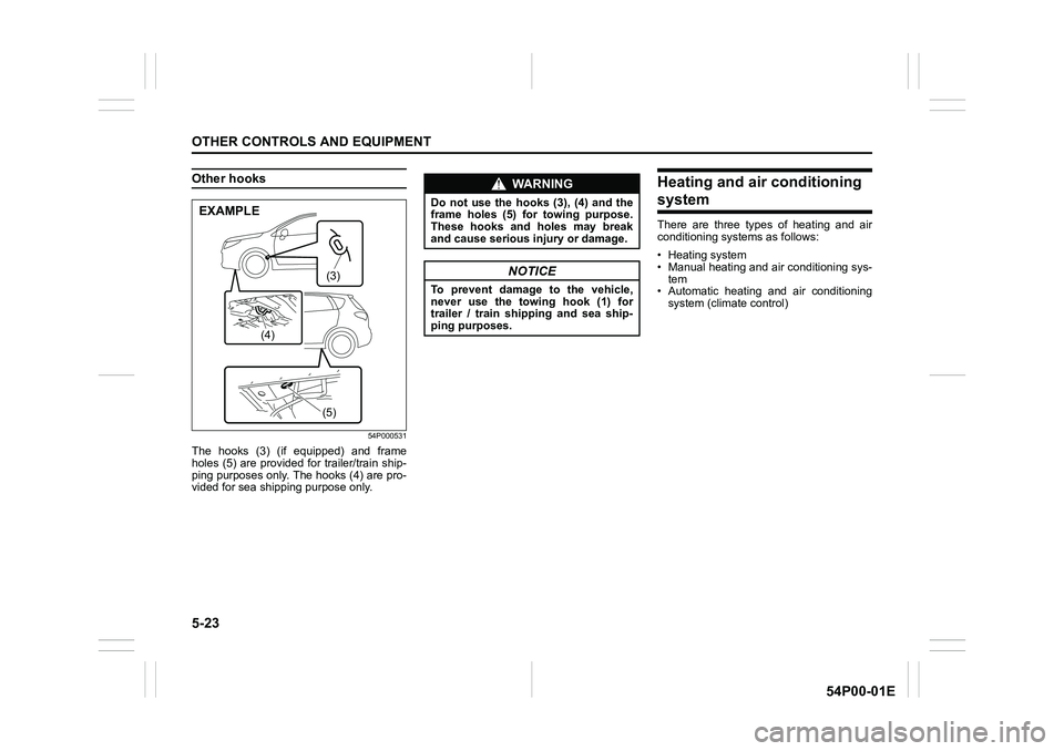
Other hooks
54P000531
The hooks (3) (if equipped) and frame
holes (5) are provided for trailer/train ship-
ping purposes only. The hooks (4) are pro-
vided for sea shipping purpose only.
Heating and air conditioning
system
There are three types of heating and air
conditioning systems as follows:
• Heating system
• Manual heating and air conditioning sys-
tem
• Automatic heating and air conditioning
system (climate control)
(3)
(4)
(5)
EXAMPLE
WA R N I N G
Do not use the hooks (3), (4) and the
frame holes (5) for towing purpose.
These hooks and holes may break
and cause serious injury or damage.
NOTICE
To prevent damage to the vehicle,
never use the towing hook (1) for
trailer / train shipping and sea ship-
ping purposes.
Page 266 of 482
5-24
OTHER CONTROLS AND EQUIPMENT
54P00-01E
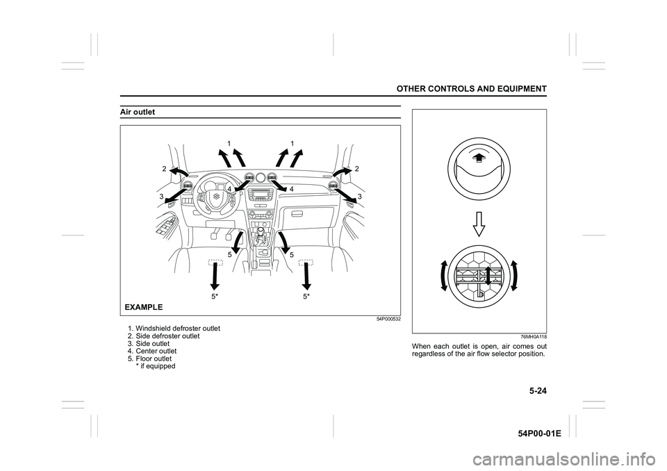
Air outlet
54P000532
1. Windshield defroster outlet
2. Side defroster outlet
3. Side outlet
4. Center outlet
5. Floor outlet
* if equipped
1
2
32
3
5
5*5
5* 4 41
EXAMPLE
76MH0A118
When each outlet is open, air comes out
regardless of the air flow selector position.
Page 267 of 482
5-25
OTHER CONTROLS AND EQUIPMENT
54P00-01E
Heating system
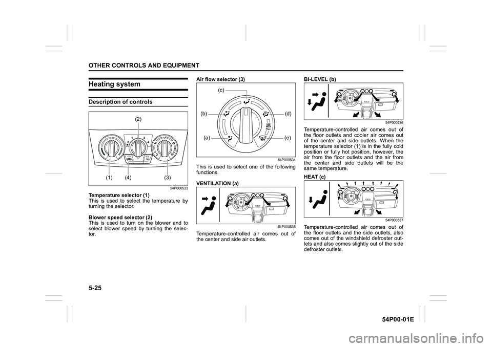
Description of controls
54P000533
Temperature selector (1)
This is used to select the temperature by
turning the selector.
Blower speed selector (2)
This is used to turn on the blower and to
select blower speed by turning the selec-
tor.Air flow selector (3)
54P000534
This is used to select one of the following
functions.
VENTILATION (a)
54P000535
Temperature-controlled air comes out of
the center and side air outlets.BI-LEVEL (b)
54P000536
Temperature-controlled air comes out of
the floor outlets and cooler air comes out
of the center and side outlets. When the
temperature selector (1) is in the fully cold
position or fully hot position, however, the
air from the floor outlets and the air from
the center and side outlets will be the
same temperature.
HEAT (c)
54P000537
Temperature-controlled air comes out of
the floor outlets and the side outlets, also
comes out of the windshield defroster out-
lets and also comes slightly out of the side
defroster outlets.
(2)
(1) (4) (3)
(a) (b)
(e)(d)
(c)
Page 268 of 482
5-26
OTHER CONTROLS AND EQUIPMENT
54P00-01E
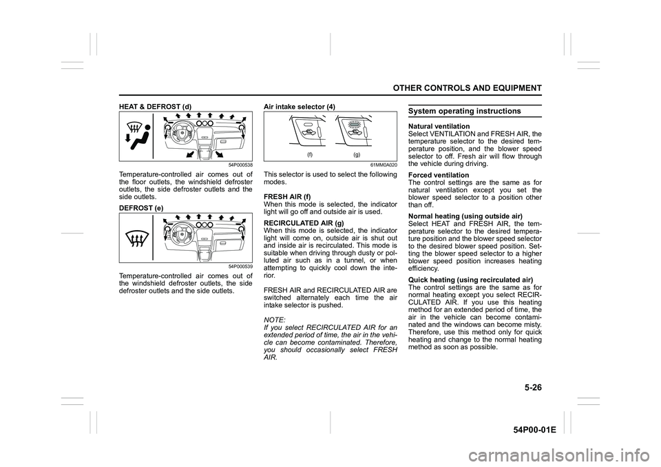
HEAT & DEFROST (d)
54P000538
Temperature-controlled air comes out of
the floor outlets, the windshield defroster
outlets, the side defroster outlets and the
side outlets.
DEFROST (e)
54P000539
Temperature-controlled air comes out of
the windshield defroster outlets, the side
defroster outlets and the side outlets.Air intake selector (4)
61MM0A020
This selector is used to select the following
modes.
FRESH AIR (f)
When this mode is selected, the indicator
light will go off and outside air is used.
RECIRCULATED AIR (g)
When this mode is selected, the indicator
light will come on, outside air is shut out
and inside air is recirculated. This mode is
suitable when driving through dusty or pol-
luted air such as in a tunnel, or when
attempting to quickly cool down the inte-
rior.
FRESH AIR and RECIRCULATED AIR are
switched alternately each time the air
intake selector is pushed.
NOTE:
If you select RECIRCULATED AIR for an
extended period of time, the air in the vehi-
cle can become contaminated. Therefore,
you should occasionally select FRESH
AIR.
System operating instructions
Natural ventilation
Select VENTILATION and FRESH AIR, the
temperature selector to the desired tem-
perature position, and the blower speed
selector to off. Fresh air will flow through
the vehicle during driving.
Forced ventilation
The control settings are the same as for
natural ventilation except you set the
blower speed selector to a position other
than off.
Normal heating (using outside air)
Select HEAT and FRESH AIR, the tem-
perature selector to the desired tempera-
ture position and the blower speed selector
to the desired blower speed position. Set-
ting the blower speed selector to a higher
blower speed position increases heating
efficiency.
Quick heating (using recirculated air)
The control settings are the same as for
normal heating except you select RECIR-
CULATED AIR. If you use this heating
method for an extended period of time, the
air in the vehicle can become contami-
nated and the windows can become misty.
Therefore, use this method only for quick
heating and change to the normal heating
method as soon as possible.
(f) (g)
Page 269 of 482
5-27
OTHER CONTROLS AND EQUIPMENT
54P00-01E
Head cooled/Feet warmed heating
Select BI-LEVEL and FRESH AIR, the
temperature selector to the desired tem-
perature position, and the blower speed
selector to the desired blower speed posi-
tion. Unless the temperature selector is in
the fully cold position or fully hot position,
the air that comes out of the center and
side outlets will be cooler than the air that
comes out of the floor outlets.
Defrosting/Feet warmed heating
Select HEAT & DEFROST and FRESH
AIR, the temperature selector to the
desired temperature position, and the
blower speed selector to high. When the
windshield has become clear, set the
blower speed selector to the desired
blower speed position.
Defrosting
Select DEFROST and FRESH AIR, the
temperature selector to the desired tem-
perature position (higher temperature pro-
vides more efficient defrosting), and the
blower speed selector to high. When the
windshield has become clear, set the
blower speed selector to the desired
blower speed position.
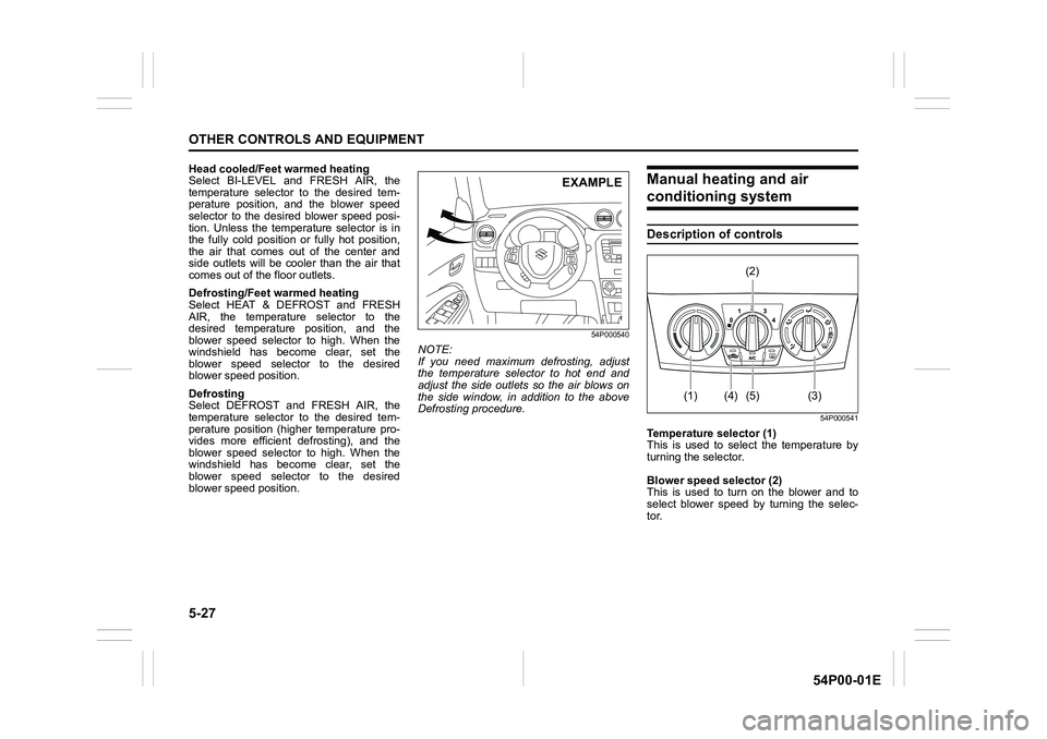
54P000540
NOTE:
If you need maximum defrosting, adjust
the temperature selector to hot end and
adjust the side outlets so the air blows on
the side window, in addition to the above
Defrosting procedure.
Manual heating and air
conditioning system
Description of controls
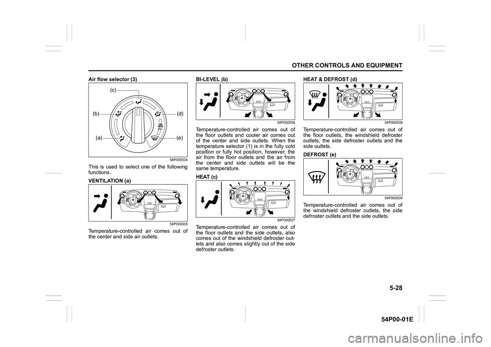
54P000541
Temperature selector (1)
This is used to select the temperature by
turning the selector.
Blower speed selector (2)
This is used to turn on the blower and to
select blower speed by turning the selec-
tor.
EXAMPLE
(2)
(1) (4) (5) (3)
Page 270 of 482
5-28
OTHER CONTROLS AND EQUIPMENT
54P00-01E
Air flow selector (3)
54P000534
This is used to select one of the following
functions.
VENTILATION (a)
54P000535
Temperature-controlled air comes out of
the center and side air outlets.BI-LEVEL (b)
54P000536
Temperature-controlled air comes out of
the floor outlets and cooler air comes out
of the center and side outlets. When the
temperature selector (1) is in the fully cold
position or fully hot position, however, the
air from the floor outlets and the air from
the center and side outlets will be the
same temperature.
HEAT (c)
54P000537
Temperature-controlled air comes out of
the floor outlets and the side outlets, also
comes out of the windshield defroster out-
lets and also comes slightly out of the side
defroster outlets.HEAT & DEFROST (d)
54P000538
Temperature-controlled air comes out of
the floor outlets, the windshield defroster
outlets, the side defroster outlets and the
side outlets.
DEFROST (e)
54P000539
Temperature-controlled air comes out of
the windshield defroster outlets, the side
defroster outlets and the side outlets.
(a) (b)
(e)(d)
(c)