engine SUZUKI IGNIS 2021 Owners Manual
[x] Cancel search | Manufacturer: SUZUKI, Model Year: 2021, Model line: IGNIS, Model: SUZUKI IGNIS 2021Pages: 505, PDF Size: 8.36 MB
Page 379 of 505
7-30
INSPECTION AND MAINTENANCE
75RM4-01E
81P60040
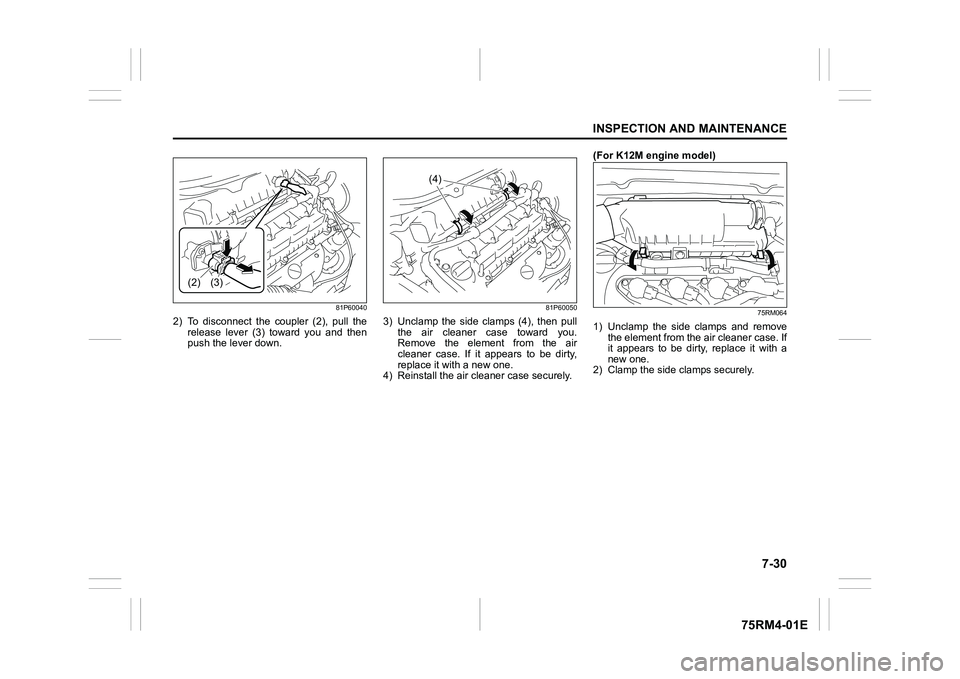
2) To disconnect the coupler (2), pull therelease lever (3) toward you and then
push the lever down.
81P60050
3) Unclamp the side clamps (4), then pullthe air cleaner case toward you.
Remove the element from the air
cleaner case. If it appears to be dirty,
replace it with a new one.
4) Reinstall the air cleaner case securely. (For K12M engine model)
75RM064
1) Unclamp the side clamps and remove
the element from the air cleaner case. If
it appears to be dirty, replace it with a
new one.
2) Clamp the side clamps securely.
(2) (3)
(4)
Page 380 of 505
7-31INSPECTION AND MAINTENANCE
75RM4-01E
Spark plugsSpark plug replacement and inspec-tion(For K12C engine model)
81PN235
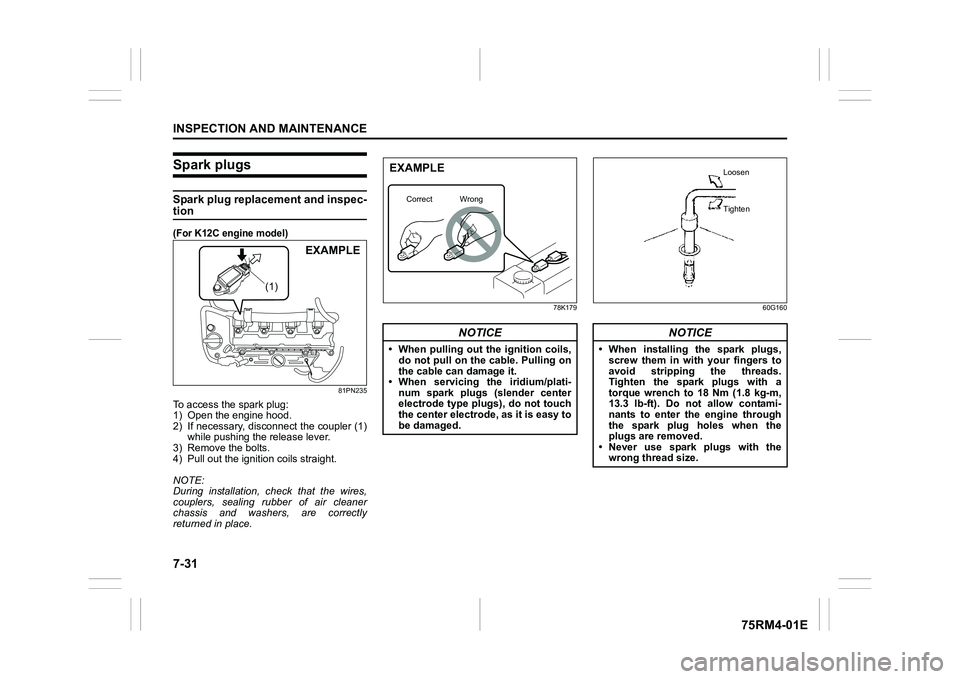
To access the spark plug:
1) Open the engine hood.
2) If necessary, disconnect the coupler (1)while pushing the release lever.
3) Remove the bolts.
4) Pull out the ignition coils straight.
NOTE:
During installation, check that the wires,
couplers, sealing rubber of air cleaner
chassis and washers, are correctly
returned in place.
78K179 60G160
(1)
EXAMPLE
NOTICE
• When pulling out the ignition coils,
do not pull on the cable. Pulling on
the cable can damage it.
• When servicing the iridium/plati-
num spark plugs (slender center
electrode type plu gs), do not touch
the center electrode, as it is easy to
be damaged.EXAMPLE
Correct Wrong
NOTICE
• When installing the spark plugs,
screw them in with your fingers to
avoid stripping the threads.
Tighten the spark plugs with a
torque wrench to 18 Nm (1.8 kg-m,
13.3 lb-ft). Do not allow contami-
nants to enter the engine through
the spark plug holes when the
plugs are removed.
• Never use spark plugs with the
wrong thread size.
Loosen
Tighten
Page 381 of 505

7-32
INSPECTION AND MAINTENANCE
75RM4-01E
54G106
Spark plug gap “a”
ILZKR6F11:
1.0 – 1.1 mm (0.039 – 0.043 in.)
(For K12M engine model)
Since special procedures, materials and
tools are required, it is recommended that
you trust this job to your authorized
SUZUKI dealer.
Continuously variable transaxle (CVT) fluidSpecified fluidUse a CVT fluid SUZUKI CVT FLUID
GREEN-2.Fluid level checkYou must check the fluid level with the CVT
fluid at normal ope rating temperature.
To check the fluid level:
1) To warm up the CVT fluid, drive the vehicle for more 5 km. NOTE:
Do not check the fluid level if you have just
driven the vehicle for a long time at high
speed, or if you have driven in city traffic in
hot weather, or if the vehicle has been pull-
ing a trailer. Wait until the fluid cools down
(about 30 minutes), or the fluid level indi-
cation will not be correct.
2) Park your vehicle on level ground.
3) Apply the parking brake and then start
the engine in “P” (Park). Let it idle for
two minutes and keep it running during
the fluid level check.
4) With your foot on the brake pedal,
move the gearshift lever through each
gear, pausing for about three seconds
in each range. Then move it back to the
“P” (Park) position.
NOTICE
When replacing spark plugs, you
should use the brand and type speci-
fied for your vehicle. For the specified
plugs, refer to “SPECIFICATIONS”
section in the end of this book. If you
wish to use a brand of spark plug
other than the specified plugs, con-
sult your SUZUKI dealer.
NOTICE
Driving with too much or too little
fluid can damage the transaxle.
NOTICE
Be sure to use the specified CVT
fluid. Using CVT fluid other than
SUZUKI CVT FLUID GREEN-2 may
damage the CVT of your vehicle.
WA R N I N G
Be sure to depress the brake pedal
when moving the gearshift lever, or
the vehicle can move suddenly.
Page 384 of 505
7-35INSPECTION AND MAINTENANCE
75RM4-01E
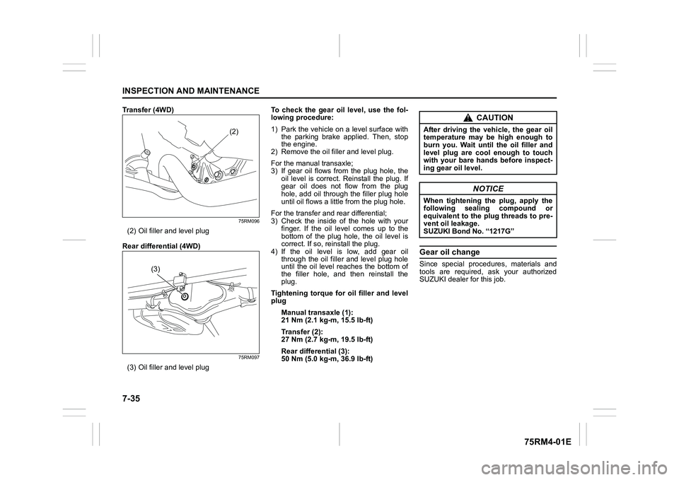
Transfer (4WD)
75RM096
(2) Oil filler and level plug
Rear differential (4WD)
75RM097
(3) Oil filler and level plug To check the gear oil level, use the fol-
lowing procedure:
1) Park the vehicle on a level surface with
the parking brake applied. Then, stop
the engine.
2) Remove the oil filler and level plug.
For the manual transaxle;
3) If gear oil flows from the plug hole, the
oil level is correct. Reinstall the plug. If
gear oil does not flow from the plug
hole, add oil through the filler plug hole
until oil flows a littl e from the plug hole.
For the transfer and rear differential;
3) Check the inside of the hole with your finger. If the oil level comes up to the
bottom of the plug hole, the oil level is
correct. If so, reinstall the plug.
4) If the oil level is low, add gear oil through the oil filler and level plug hole
until the oil level reaches the bottom of
the filler hole, and then reinstall the
plug.
Tightening torque for oil filler and level
plug
Manual transaxle (1):
21 Nm (2.1 kg-m, 15.5 lb-ft)
Transfer (2):
27 Nm (2.7 kg-m, 19.5 lb-ft)
Rear differential (3):
50 Nm (5.0 kg-m, 36.9 lb-ft)
Gear oil changeSince special procedures, materials and
tools are required, ask your authorized
SUZUKI dealer for this job.
(2)
(3)
CAUTION
After driving the vehicle, the gear oil
temperature may be high enough to
burn you. Wait until the oil filler and
level plug are cool enough to touch
with your bare hands before inspect-
ing gear oil level.
NOTICE
When tightening the plug, apply the
following sealing compound or
equivalent to the plug threads to pre-
vent oil leakage.
SUZUKI Bond No. “1217G”
Page 385 of 505

7-36
INSPECTION AND MAINTENANCE
75RM4-01E
Clutch pedalCable control clutch
54G274
Clutch pedal play “d”:
10 – 15 mm (0.4 – 0.6 in.)
Measure the clutch pedal play by moving
the clutch pedal with your hand and mea-
suring the distance it moves until you feel
slight resistance. The play in the clutch
pedal should be between the specified val-
ues. If the play is more or less than the
above, or clutch dragging is felt with the
pedal fully depressed, have the clutch
inspected by your SUZUKI dealer.
BrakesBrake fluid
75RM095
Check the brake fluid level by looking at
the reservoir in the engine compartment.
Check that the fluid level is between “MAX”
and “MIN” lines.
EXAMPLE
NOTICE
If your brake fluid level is near the
“MIN” line, there is a possibility of
brake pad and/or shoe wear and brake
fluid leakage.
Consult with your authorized SUZUKI
dealer regarding this possibility
before filling the reservoir.
WA R N I N G
Failure to follow the guidelines below
can result in personal injury or seri-
ous damage to the brake system.
• If the brake fluid in the reservoir drops below a certain level, the
brake warning light on the instru-
ment cluster will come on (the
engine must be running with the
parking brake fully disengaged).
Should the light come on, immedi-
ately ask your SUZUKI dealer to
inspect the brake system.
• A rapid fluid loss indicates leakage
in the brake system which should
be inspected by your SUZUKI
dealer immediately.
• Do not use any fluid other than SAE J1703 or DOT3 brake fluid. Do not
use reclaimed fluid or fluid that has
been stored in old or open contain-
ers. It is essential that foreign parti-
cles and other liquids are kept out
of the brake fluid reservoir.
CAUTION
Brake fluid can harm your eyes and
damage painted surfaces. Be careful
when refilling the reservoir.
Page 386 of 505
7-37INSPECTION AND MAINTENANCE
75RM4-01E
NOTE:
• The fluid level can be expected to gradu-ally fall as the brake pad and/or shoe
wear.
• Brake fluid absorbs water over time and
brake fluid with high water content may
cause vapor lock or brake system mal-
function.
Replace your brake fluid in accordance
with the maintenance schedule in your
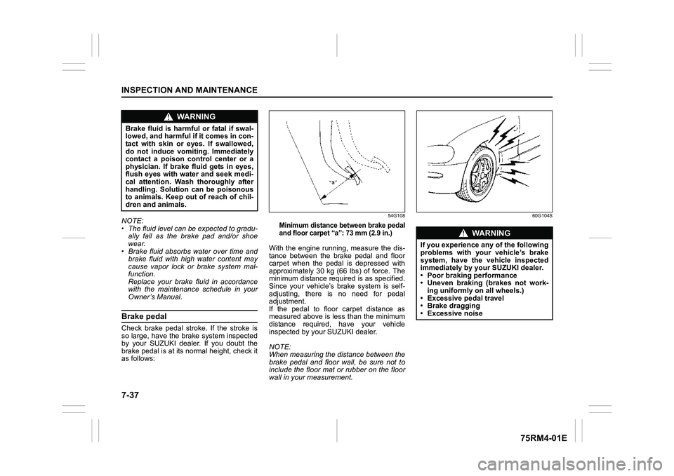
Owner’s Manual.Brake pedalCheck brake pedal stroke. If the stroke is
so large, have the brake system inspected
by your SUZUKI dealer. If you doubt the
brake pedal is at its normal height, check it
as follows:
54G108
Minimum distance between brake pedal
and floor carpet “a”: 73 mm (2.9 in.)
With the engine running, measure the dis-
tance between the brake pedal and floor
carpet when the pedal is depressed with
approximately 30 kg (66 lbs) of force. The
minimum distance required is as specified.
Since your vehicle’s brake system is self-
adjusting, there is no need for pedal
adjustment.
If the pedal to floor carpet distance as
measured above is less than the minimum
distance required, have your vehicle
inspected by your SUZUKI dealer.
NOTE:
When measuring the distance between the
brake pedal and floor wall, be sure not to
include the floor mat or rubber on the floor
wall in your measurement.
60G104S
WA R N I N G
Brake fluid is harmful or fatal if swal-
lowed, and harmful if it comes in con-
tact with skin or eyes. If swallowed,
do not induce vomiting. Immediately
contact a poison control center or a
physician. If brake fluid gets in eyes,
flush eyes with water and seek medi-
cal attention. Wash thoroughly after
handling. Solution can be poisonous
to animals. Keep out of reach of chil-
dren and animals.
WA R N I N G
If you experience any of the following
problems with your vehicle’s brake
system, have the vehicle inspected
immediately by your SUZUKI dealer.
• Poor braking performance
• Uneven braking (brakes not work- ing uniformly on all wheels.)
• Excessive pedal travel
• Brake dragging
• Excessive noise
Page 394 of 505
7-45INSPECTION AND MAINTENANCE
75RM4-01E
Lithium-ion battery (if equipped)This battery is installed only in models
equipped with the ENG A-STOP system
and is located under the front passenger’s
seat.
• The lithium-ion battery is maintenance-free. However, in order to avoid a flat
battery, drive the vehicle once a month
for at least 30 minutes to recharge the
battery.
• When replacing or disposing of the lith- ium-ion battery, consult your authorized
SUZUKI dealer.
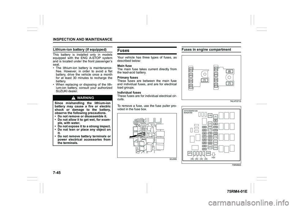
FusesYour vehicle has three types of fuses, as
described below:
Main fuse
The main fuse takes current directly from
the lead-acid battery.
Primary fuses
These fuses are between the main fuse
and individual fuses, and are for electrical
load groups.
Individual fuses
These fuses are for indi vidual electrical cir-
cuits.
To remove a fuse, use the fuse puller pro-
vided in the fuse box.
63J095
Fuses in engine compartment
74LHT0715
75RM065
WA R N I N G
Since mishandling the lithium-ion
battery may cause a fire or electric
shock or damage to the battery,
observe the following precautions.
• Do not remove or disassemble it.
• Do not allow it to get wet, for exam- ple, with water.
• Do not expose it to a strong impact.
• Do not lean or place any object on it.
• Do not remove battery terminals or power electrical accessories from
the terminals.
(5)
(3)
(4)
(2) (1)(5)
(4)
(3)
(2) (1)
(6)
(7)
(16)
(17)
(18)
(19)
(20)
(21)
(22)
(23)
(25)
(24)
(26)
(29)
(27)
(28)
(30)
(31)
(32)
(37)
(33)
(34)
(35)
(36) (8)
(9)
(10)
(11)
(12)
(13)
(14)
(15)FRONT
Page 395 of 505
7-46
INSPECTION AND MAINTENANCE
75RM4-01E
*1: Models with ENG A-STOP
*2: CVT models with ENG A-STOP
*3: Auto Gear Shift models
*4: Models with Auto-on headlight system
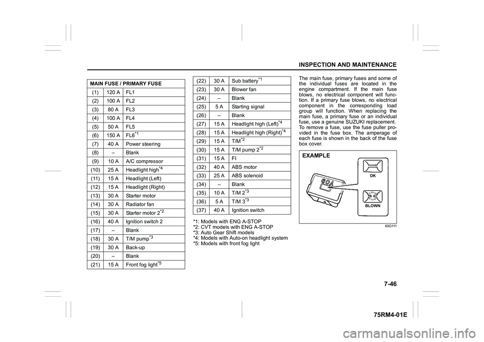
*5: Models with front fog light The main fuse, primary fuses and some of
the individual fuses are located in the
engine compartment. If the main fuse
blows, no electrical component will func-
tion. If a primary fuse blows, no electrical
component in the corresponding load
group will function. When replacing the
main fuse, a primary fuse or an individual
fuse, use a genuine S
UZUKI replacement.
To remove a fuse, use the fuse puller pro-
vided in the fuse box. The amperage of
each fuse is shown in the back of the fuse
box cover.
60G111
MAIN FUSE / PRIMARY FUSE
(1) 120 A FL1
(2) 100 A FL2
(3) 80 A FL3
(4) 100 A FL4
(5) 50 A FL5
(6) 150 A FL6
*1
(7) 40 A Power steering
(8) – Blank
(9) 10 A A/C compressor
(10) 25 A Headlight high
*4
(11) 15 A Headlight (Left)
(12) 15 A Headlight (Right)
(13) 30 A Starter motor
(14) 30 A Radiator fan
(15) 30 A Starter motor 2
*2
(16) 40 A Ignition switch 2
(17) – Blank
(18) 30 A T/M pump
*3
(19) 30 A Back-up
(20) – Blank
(21) 15 A Front fog light
*5
(22) 30 A Sub battery
*1
(23) 30 A Blower fan
(24) – Blank
(25) 5 A Starting signal
(26) – Blank
(27) 15 A Headlight high (Left)
*4
(28) 15 A Headlight high (Right)
*4
(29) 15 A T/M
*2
(30) 15 A T/M pump 2
*2
(31) 15 A FI
(32) 40 A ABS motor
(33) 25 A ABS solenoid
(34) – Blank
(35) 10 A T/M 2
*3
(36) 5 A T/M 3
*3
(37) 40 A Ignition switch
EXAMPLE
BLOWN OK
Page 398 of 505
7-49INSPECTION AND MAINTENANCE
75RM4-01E
Bulb replacement
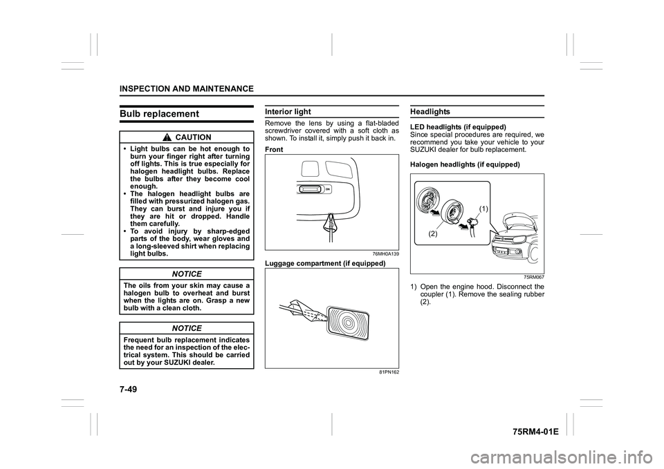
Interior lightRemove the lens by using a flat-bladed
screwdriver covered with a soft cloth as
shown. To install it, simply push it back in.
Front
76MH0A139
Luggage compartmen t (if equipped)
81PN162
HeadlightsLED headlights (if equipped)
Since special procedures are required, we
recommend you take your vehicle to your
SUZUKI dealer for bulb replacement.
Halogen headlights (if equipped)
75RM067
1) Open the engine hood. Disconnect the
coupler (1). Remove the sealing rubber
(2).
CAUTION
• Light bulbs can be hot enough to burn your finger right after turning
off lights. This is true especially for
halogen headlight bulbs. Replace
the bulbs after they become cool
enough.
• The halogen headlight bulbs are filled with pressurized halogen gas.
They can burst and injure you if
they are hit or dropped. Handle
them carefully.
• To avoid injury by sharp-edged
parts of the body, wear gloves and
a long-sleeved shirt when replacing
light bulbs.
NOTICE
The oils from your skin may cause a
halogen bulb to overheat and burst
when the lights are on. Grasp a new
bulb with a clean cloth.
NOTICE
Frequent bulb replacement indicates
the need for an inspection of the elec-
trical system. This should be carried
out by your SUZUKI dealer.
(1)
(2)
Page 400 of 505
7-51INSPECTION AND MAINTENANCE
75RM4-01E
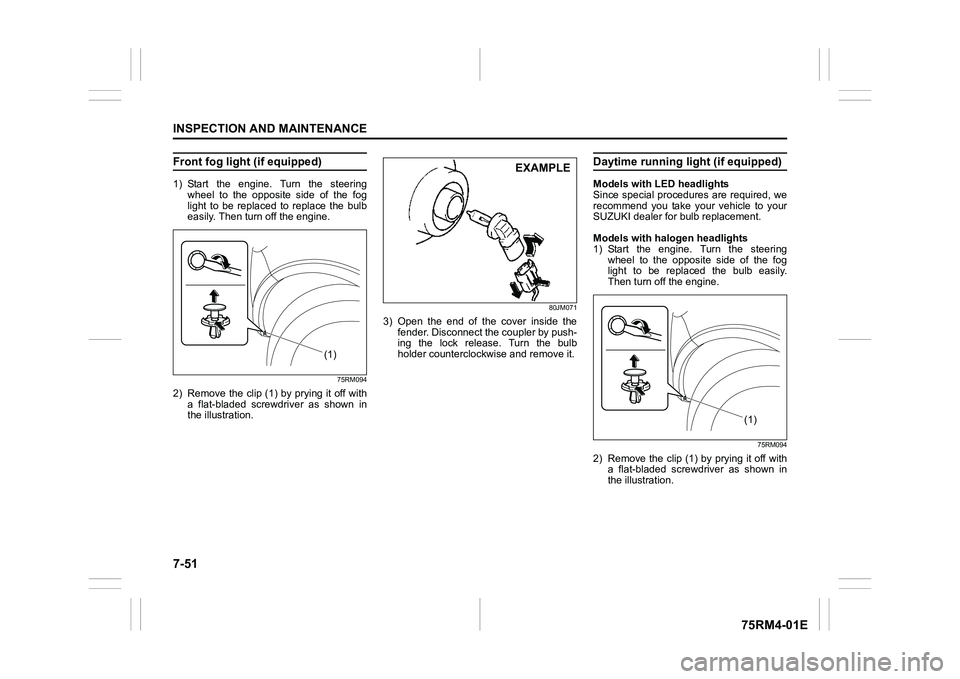
Front fog light (if equipped)1) Start the engine. Turn the steeringwheel to the opposite side of the fog
light to be replaced to replace the bulb
easily. Then turn off the engine.
75RM094
2) Remove the clip (1) by prying it off witha flat-bladed screwdriver as shown in
the illustration.
80JM071
3) Open the end of the cover inside thefender. Disconnect the coupler by push-
ing the lock release. Turn the bulb
holder counterclockwise and remove it.
Daytime running light (if equipped)Models with LED headlights
Since special procedures are required, we
recommend you take your vehicle to your
SUZUKI dealer for bulb replacement.
Models with halogen headlights
1) Start the engine. Turn the steering
wheel to the opposite side of the fog
light to be replaced the bulb easily.
Then turn off the engine.
75RM094
2) Remove the clip (1) by prying it off witha flat-bladed screwdriver as shown in
the illustration.
(1)
EXAMPLE
(1F