cvt SUZUKI IGNIS 2022 Workshop Manual
[x] Cancel search | Manufacturer: SUZUKI, Model Year: 2022, Model line: IGNIS, Model: SUZUKI IGNIS 2022Pages: 505, PDF Size: 8.36 MB
Page 377 of 505
7-28
INSPECTION AND MAINTENANCE
75RM4-01E
Engine coolantSelection of coolantTo maintain optimum performance and
durability of your engine, use SUZUKI gen-
uine coolant or equivalent.
NOTE:
If you use the engine coolant other than
the SUZUKI LLC: Super (Blue) for replace-
ment, follow the schedule of SUZUKI LLC:
Standard (Green). To see the detail of the
maintenance schedule, refer to “Periodic
maintenance schedule” in this section.
This type of coolant is the best for cooling
system for the following reasons:
• The coolant helps maintain properengine temperature.
• It gives proper protection against freez- ing and boiling.
• It gives proper protection against corro- sion and rust. Failure to use the proper coolant can dam-
age your cooling system. Your authorized
SUZUKI dealer can help you select the
proper coolant.
Coolant level checkCheck the coolant le
vel at the reservoir
tank, not at the radiator. With the engine
cool, the coolant level should be between
“FULL” and “LOW” marks.Adding coolant
NOTICE
SUZUKI LLC: Super (Blue) coolant;
This coolant is already diluted to the
proper percentage. Do not dilute with
distilled water additionally. Doing so
may result in the possibility of freez-
ing and/or overheating coolant.
NOTICE
To avoid damaging your cooling sys-
tem:
• Always use a high quality ethylene
glycol base non-silicate type cool-
ant diluted with distilled water at
the correct mixture concentration.
• Check that the proper mix is 50/50
coolant to distill ed water and in no
case higher than 70/30. Concentra-
tions greater than 70/30 coolant to
distilled water will cause overheat-
ing conditions.
• Do not use straight coolant nor plain water (except SUZUKI LLC:
Super (Blue)).
• Do not add extra inhibitors or addi- tives. They may not be compatible
with your cooling system.
• Do not mix different types of base coolants. Doing so may result in
accelerated seal wear and/or the
possibility of severe overheating
and extensive engine or CVT (if
equipped) damage.
WA R N I N G
Swallowing engine coolant can cause
severe injury or death. Inhaling cool-
ant mist or vapors or getting coolant
in your eyes could result in severe
injury.
• Do not drink antifreeze or coolantsolution. If swallowed, do not
induce vomiting. Immediately con-
tact a poison control center or a
physician.
• Avoid inhaling coolant mist or hot
vapors. If inhaled, remove to a
fresh air area.
• If coolant gets in the eyes, flush
with water and seek medical atten-
tion.
• Wash thoroughly after handling
coolant.
• Keep engine coolant out of the
reach of children and pets.
Page 381 of 505

7-32
INSPECTION AND MAINTENANCE
75RM4-01E
54G106
Spark plug gap “a”
ILZKR6F11:
1.0 – 1.1 mm (0.039 – 0.043 in.)
(For K12M engine model)
Since special procedures, materials and
tools are required, it is recommended that
you trust this job to your authorized
SUZUKI dealer.
Continuously variable transaxle (CVT) fluidSpecified fluidUse a CVT fluid SUZUKI CVT FLUID
GREEN-2.Fluid level checkYou must check the fluid level with the CVT
fluid at normal ope rating temperature.
To check the fluid level:
1) To warm up the CVT fluid, drive the vehicle for more 5 km. NOTE:
Do not check the fluid level if you have just
driven the vehicle for a long time at high
speed, or if you have driven in city traffic in
hot weather, or if the vehicle has been pull-
ing a trailer. Wait until the fluid cools down
(about 30 minutes), or the fluid level indi-
cation will not be correct.
2) Park your vehicle on level ground.
3) Apply the parking brake and then start
the engine in “P” (Park). Let it idle for
two minutes and keep it running during
the fluid level check.
4) With your foot on the brake pedal,
move the gearshift lever through each
gear, pausing for about three seconds
in each range. Then move it back to the
“P” (Park) position.
NOTICE
When replacing spark plugs, you
should use the brand and type speci-
fied for your vehicle. For the specified
plugs, refer to “SPECIFICATIONS”
section in the end of this book. If you
wish to use a brand of spark plug
other than the specified plugs, con-
sult your SUZUKI dealer.
NOTICE
Driving with too much or too little
fluid can damage the transaxle.
NOTICE
Be sure to use the specified CVT
fluid. Using CVT fluid other than
SUZUKI CVT FLUID GREEN-2 may
damage the CVT of your vehicle.
WA R N I N G
Be sure to depress the brake pedal
when moving the gearshift lever, or
the vehicle can move suddenly.
Page 382 of 505
7-33INSPECTION AND MAINTENANCE
75RM4-01E
75F086
81PN159 75RM370
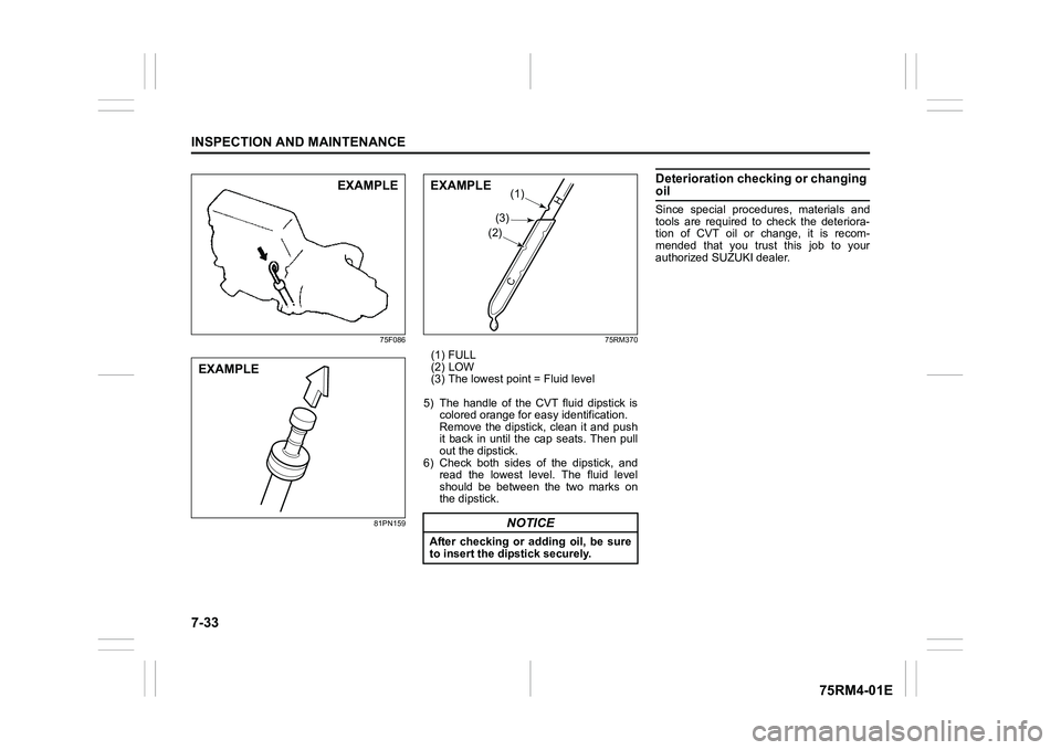
(1) FULL
(2) LOW
(3) The lowest point = Fluid level
5) The handle of the CVT fluid dipstick is colored orange for ea sy identification.
Remove the dipstick, clean it and push
it back in until the cap seats. Then pull
out the dipstick.
6) Check both sides of the dipstick, and read the lowest level. The fluid level
should be between the two marks on
the dipstick.
Deterioration checking or changing oilSince special procedures, materials and
tools are required to check the deteriora-
tion of CVT oil or change, it is recom-
mended that you trust this job to your
authorized SUZUKI dealer.
EXAMPLE
EXAMPLE
NOTICE
After checking or adding oil, be sure
to insert the di pstick securely.
(3)
(1)
(2)
C
H
�(�Ο�Ν�0�3�/�(
Page 395 of 505
7-46
INSPECTION AND MAINTENANCE
75RM4-01E
*1: Models with ENG A-STOP
*2: CVT models with ENG A-STOP
*3: Auto Gear Shift models
*4: Models with Auto-on headlight system
*5: Models with front fog light The main fuse, primary fuses and some of
the individual fuses are located in the
engine compartment. If the main fuse
blows, no electrical component will func-
tion. If a primary fuse blows, no electrical
component in the corresponding load
group will function. When replacing the
main fuse, a primary fuse or an individual
fuse, use a genuine S
UZUKI replacement.
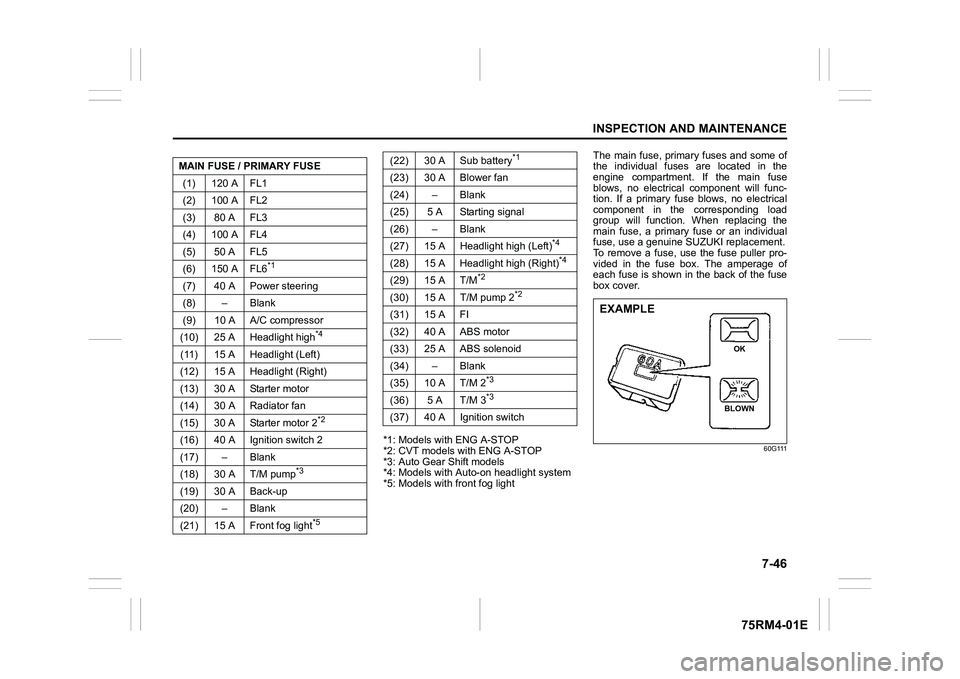
To remove a fuse, use the fuse puller pro-
vided in the fuse box. The amperage of
each fuse is shown in the back of the fuse
box cover.
60G111
MAIN FUSE / PRIMARY FUSE
(1) 120 A FL1
(2) 100 A FL2
(3) 80 A FL3
(4) 100 A FL4
(5) 50 A FL5
(6) 150 A FL6
*1
(7) 40 A Power steering
(8) – Blank
(9) 10 A A/C compressor
(10) 25 A Headlight high
*4
(11) 15 A Headlight (Left)
(12) 15 A Headlight (Right)
(13) 30 A Starter motor
(14) 30 A Radiator fan
(15) 30 A Starter motor 2
*2
(16) 40 A Ignition switch 2
(17) – Blank
(18) 30 A T/M pump
*3
(19) 30 A Back-up
(20) – Blank
(21) 15 A Front fog light
*5
(22) 30 A Sub battery
*1
(23) 30 A Blower fan
(24) – Blank
(25) 5 A Starting signal
(26) – Blank
(27) 15 A Headlight high (Left)
*4
(28) 15 A Headlight high (Right)
*4
(29) 15 A T/M
*2
(30) 15 A T/M pump 2
*2
(31) 15 A FI
(32) 40 A ABS motor
(33) 25 A ABS solenoid
(34) – Blank
(35) 10 A T/M 2
*3
(36) 5 A T/M 3
*3
(37) 40 A Ignition switch
EXAMPLE
BLOWN OK
Page 410 of 505
8-1EMERGENCY SERVICE
75RM4-01E
Tire changing tool
75RM076
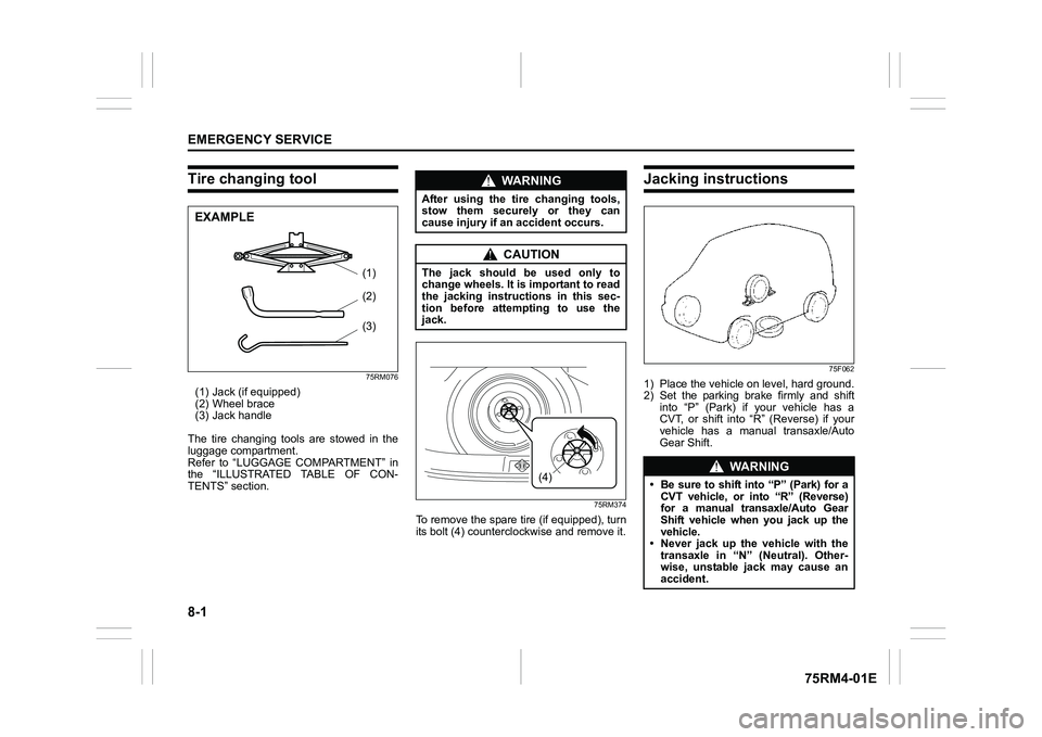
(1) Jack (if equipped)
(2) Wheel brace
(3) Jack handle
The tire changing tools are stowed in the
luggage compartment.
Refer to “LUGGAGE COMPARTMENT” in
the “ILLUSTRATED TABLE OF CON-
TENTS” section.
75RM374
To remove the spare tire (if equipped), turn
its bolt (4) countercl ockwise and remove it.
Jacking instructions
75F062
1) Place the vehicle on level, hard ground.
2) Set the parking brake firmly and shift into “P” (Park) if your vehicle has a
CVT, or shift into “R” (Reverse) if your
vehicle has a manual transaxle/Auto
Gear Shift.
(3)(2)
(1)
EXAMPLE
WA R N I N G
After using the tire changing tools,
stow them securely or they can
cause injury if an accident occurs.
CAUTION
The jack should be used only to
change wheels. It is important to read
the jacking instructions in this sec-
tion before attempting to use the
jack.
(4)
�:�Ν �5 �1 �, �1 �*
�
Page 413 of 505
8-4
EMERGENCY SERVICE
75RM4-01E
NOTE:
For more details, contact an authorized
SUZUKI dealer.Changing wheelsTo change a wheel, use the following pro-
cedure:
1) Remove the jack (if equipped), toolsand spare wheel from the vehicle.
2) Loosen, but do not remove the wheel
nuts.
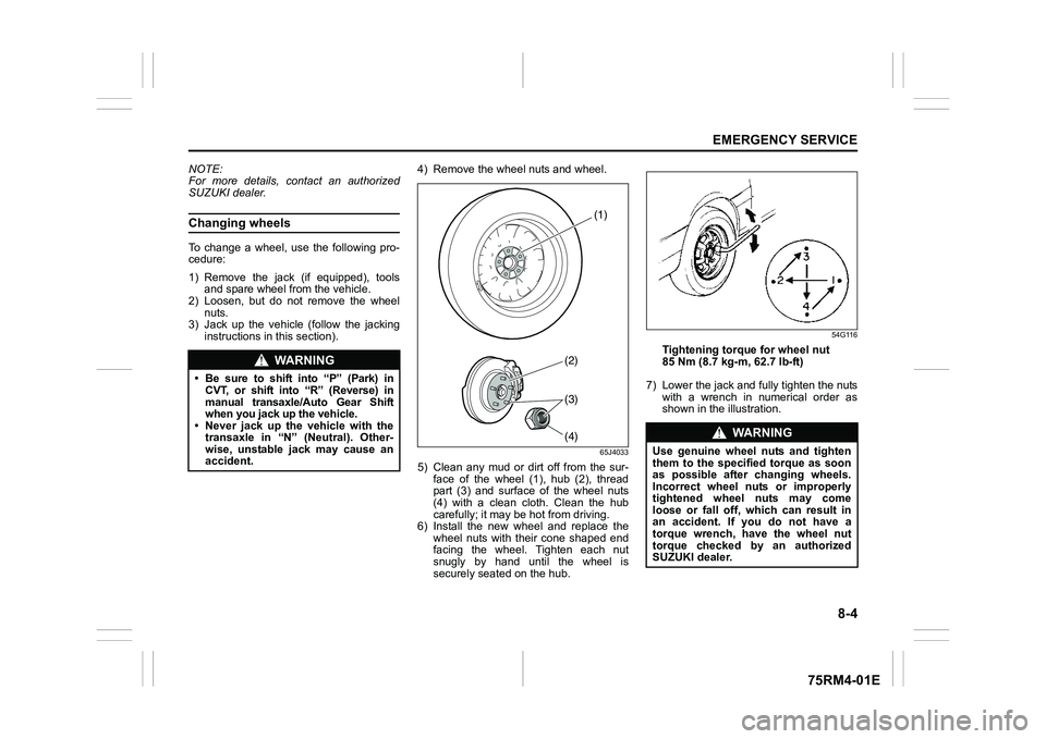
3) Jack up the vehicle (follow the jacking instructions in this section). 4) Remove the wheel nuts and wheel.
65J4033
5) Clean any mud or dirt off from the sur-
face of the wheel (1), hub (2), thread
part (3) and surface of the wheel nuts
(4) with a clean cloth. Clean the hub
carefully; it m ay be hot from driving.
6) Install the new wheel and replace the
wheel nuts with their cone shaped end
facing the wheel. Tighten each nut
snugly by hand until the wheel is
securely seated on the hub.
54G116
Tightening torque for wheel nut
85 Nm (8.7 kg-m, 62.7 lb-ft)
7) Lower the jack and fully tighten the nuts with a wrench in numerical order as
shown in the illustration.
WA R N I N G
• Be sure to shift into “P” (Park) inCVT, or shift into “R” (Reverse) in
manual transaxle/Auto Gear Shift
when you jack up the vehicle.• Never jack up the vehicle with the
transaxle in “N” (Neutral). Other-
wise, unstable jack may cause an
accident.
(2)(4)
(1)
(3)
WA R N I N G
Use genuine wheel nuts and tighten
them to the specified torque as soon
as possible after changing wheels.
Incorrect wheel nut s or improperly
tightened wheel nuts may come
loose or fall off, which can result in
an accident. If you do not have a
torque wrench, have the wheel nut
torque checked by an authorized
SUZUKI dealer.
Page 416 of 505
8-7EMERGENCY SERVICE
75RM4-01E
Emergency repair1) Place the vehicle on level, hard ground.
Set the parking brake firmly and shift
into “R” (Reverse) if your vehicle has a
manual transaxle/Auto Gear Shift, or
shift into “P” (Park) if your vehicle has a
CVT.
Turn on the hazard warning flasher if
your vehicle is near traffic.
Block the front and rear of the wheel
diagonally opposite of the wheel being
repaired.
2) Take out the sealant bottle (2) and the compressor, and shake the bottle well.
NOTE:
Shake the bottle well before screwing the
filler hose onto the bottle.
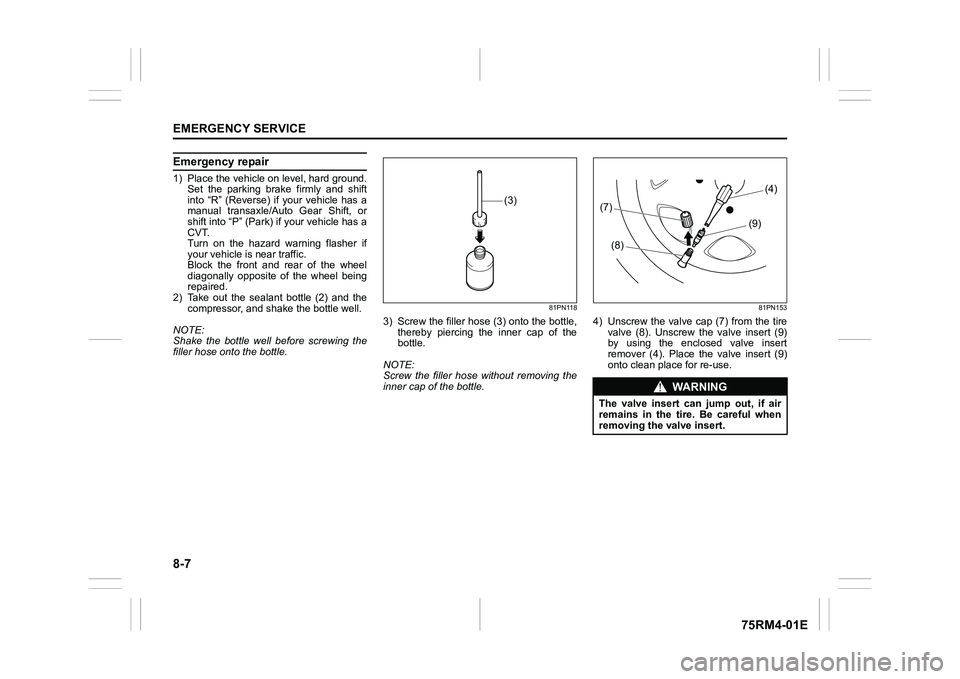
81PN118
3) Screw the filler hose (3) onto the bottle, thereby piercing the inner cap of the
bottle.
NOTE:
Screw the filler hose without removing the
inner cap of the bottle.
81PN153
4) Unscrew the valve cap (7) from the tire valve (8). Unscrew the valve insert (9)
by using the enclosed valve insert
remover (4). Place the valve insert (9)
onto clean place for re-use.
(3)
WA R N I N G
The valve insert can jump out, if air
remains in the tire. Be careful when
removing the valve insert.(7)
(8) (9)(4)
Page 419 of 505
8-10
EMERGENCY SERVICE
75RM4-01E
Using compressor to inflate a tire1) Place the vehicle on level, hard ground.
Set the parking brake firmly and shift
into “P” (Park) if your vehicle has a
CVT, or shift into “R” (Reverse) if your
vehicle has a manual transaxle or Auto
Gear Shift.
2) Take out the compressor.
3) Unscrew the valve cap from the tire valve.
4) Connect the air ho se of the compressor
to the tire valve.
5) Connect the power plug of the com- pressor to the accessory socket. For a
manual transaxle or an Auto Gear Shift
vehicle, shift from “R” (Reverse) into “N”
(Neutral). Start the engine. Switch on
the compressor. Inflate the tire to the
required air pressure.
Jump-starting instructions
1) Use only a 12-volt lead-acid battery to
jump-start your vehicle. Position the
good 12-volt lead-acid battery close to
your vehicle so that the jump leads will
reach both batteries. When using a bat-
tery installed on another vehicle, check
that two vehicles do not touch each
other. Set the parking brakes fully on
both vehicles.
2) Turn off all vehicle accessories, except those necessary for safety reasons (for
example, headlights or hazard lights).
NOTICE
Do not operate the compressor for
longer than 10 minutes. It can cause
overheating of the compressor.
WA R N I N G
• Never attempt to jump-start your
vehicle if the lead-acid battery
appears to be frozen. Batteries in
this condition may explode.
• When making jump lead connec- tions, check that your hands and
the jump leads remain clear from
pulleys, belts or fans.
• Lead-acid batteries produce flam-
mable hydrogen gas. Keep flames
and sparks away from the battery
or an explosion may occur. Never
smoke when working near the bat-
tery.
• If the booster ba ttery you use for
jump-starting is installed in another
vehicle, check that the two vehicles
are not touching each other.
• If your lead-acid battery discharges repeatedly, for no apparent reason,
have your vehicle inspected by an
authorized SUZUKI dealer.
• To avoid harm to yourself or dam- age to your vehicle or battery, fol-
low the jump-starting instructions
below.
If you are in doubt, call for qualified
road service.
NOTICE
Your vehicle should not be started by
pushing or towing. This starting
method could result in permanent
damage to the catalytic converter.
Use jump leads to start a vehicle with
a weak or flat battery.
Page 421 of 505
8-12
EMERGENCY SERVICE
75RM4-01E
2-wheel drive (2WD) CVTCVT vehicles may be towed using either of
the following methods.
1) From the front, with the front wheelslifted and the rear wheels on the
ground. Before towing, make sure that
the parking brak e is released.
2) From the rear, with the rear wheels
lifted and a dolly under the front wheels.
2-wheel drive (2WD) manual tran-saxle or Auto Gear ShiftManual transaxle vehicles or Auto Gear
Shift vehicles may be towed using either of
the following methods.
1) From the front, with the front wheelslifted and the rear wheels on the
ground. Before towing, check that the
parking brake is released.
2) From the rear, with the rear wheels
lifted and the front wheels on the
ground, provided the steering and
drivetrain are in operational condition.
Before towing, check that transaxle is in
neutral, the steering wheel is unlocked
(vehicle without keyl ess push start sys-
tem - the ignition key should be in
“ACC” position) (vehicle with keyless
push start system - the ignition mode is
ACC), and the steering wheel is
secured with a clamping device
designed for towing service.
4-wheel drive (4WD)Your vehicle should be towed under one of
the following conditions:
1) With all four wheels on a flat-bed truck.
2) With the front or rear wheels lifted and a dolly under the other wheels.
NOTICE
Towing your vehicle with the front
wheels on the ground can result in
damage to the CVT.
NOTICE
The steering column is not strong
enough to withstand shocks trans-
mitted from the fr ont wheels during
towing. Always unlock the steering
wheel before towing.
NOTICE
After shifting the Auto Gear Shift
gearshift lever to the “N” position,
always check the gear position indi-
cator in the instrument cluster shows
the “N” position to make sure that the
transaxle is disengaged.
If the transaxle cannot be put in neu-
tral, turn the key from the “LOCK” to
the “ON” position or press the engine
switch to change the ignition mode to
ON, and move the Auto Gear Shift
gearshift lever from “N” to “D”, “M”
or “R”, then back to “N” again. Then
turn the key from the “ON” to the
“LOCK” position or press the engine
switch to change the ignition mode to
LOCK (OFF). These procedures may
help put the transaxle in neutral. If
the transaxle still cannot be put in
neutral, you cannot tow the vehicle
without using a towing dolly.
Page 433 of 505
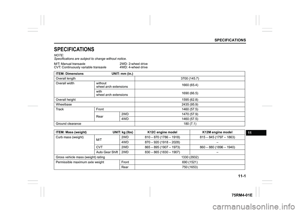
11-1
SPECIFICATIONS
75RM4-01E
11
SPECIFICATIONSNOTE:
Specifications are subject to change without notice.
M/T: Manual transaxle
CVT: Continuously variable transaxle 2WD: 2-wheel drive
4WD: 4-wheel drive
ITEM: Dimensions UNIT: mm (in.)
Overall length 3700 (145.7)
Overall width without wheel arch extensions 1660 (65.4)
with
wheel arch extensions 1690 (66.5)
Overall height 1595 (62.8)
Wheelbase 2435 (95.9)
Track Front 1460 (57.5)
Rear2WD 1470 (57.9)
4WD 1460 (57.5)
Ground clearance 180 (7.1)
ITEM: Mass (weight) UNIT: kg (lbs) K12C engine model K12M engine m odel
Curb mass (weight) M/T2WD 810 – 870 (1786 – 1918)
815 – 845 (1797 – 1863)
4WD 870 – 920 (1918 – 2028) –
CVT 2WD 865 – 895 ( 1907 – 1973) 860 – 880 (1896 – 1940)
Auto Gear Shift 2WD 8 30 – 865 (1830 – 1907) –
Gross vehicle mass (wei ght) rating 1330 (2932)
Permissible maximum axle weight Front 690 (1521) Rear 750 (1653)