Ps sensor SUZUKI JIMNY 2005 3.G Service Workshop Manual
[x] Cancel search | Manufacturer: SUZUKI, Model Year: 2005, Model line: JIMNY, Model: SUZUKI JIMNY 2005 3.GPages: 687, PDF Size: 13.38 MB
Page 504 of 687
Downloaded from www.Manualslib.com manuals search engine ENGINE MECHANICAL (M13 ENGINE) 6A1-23
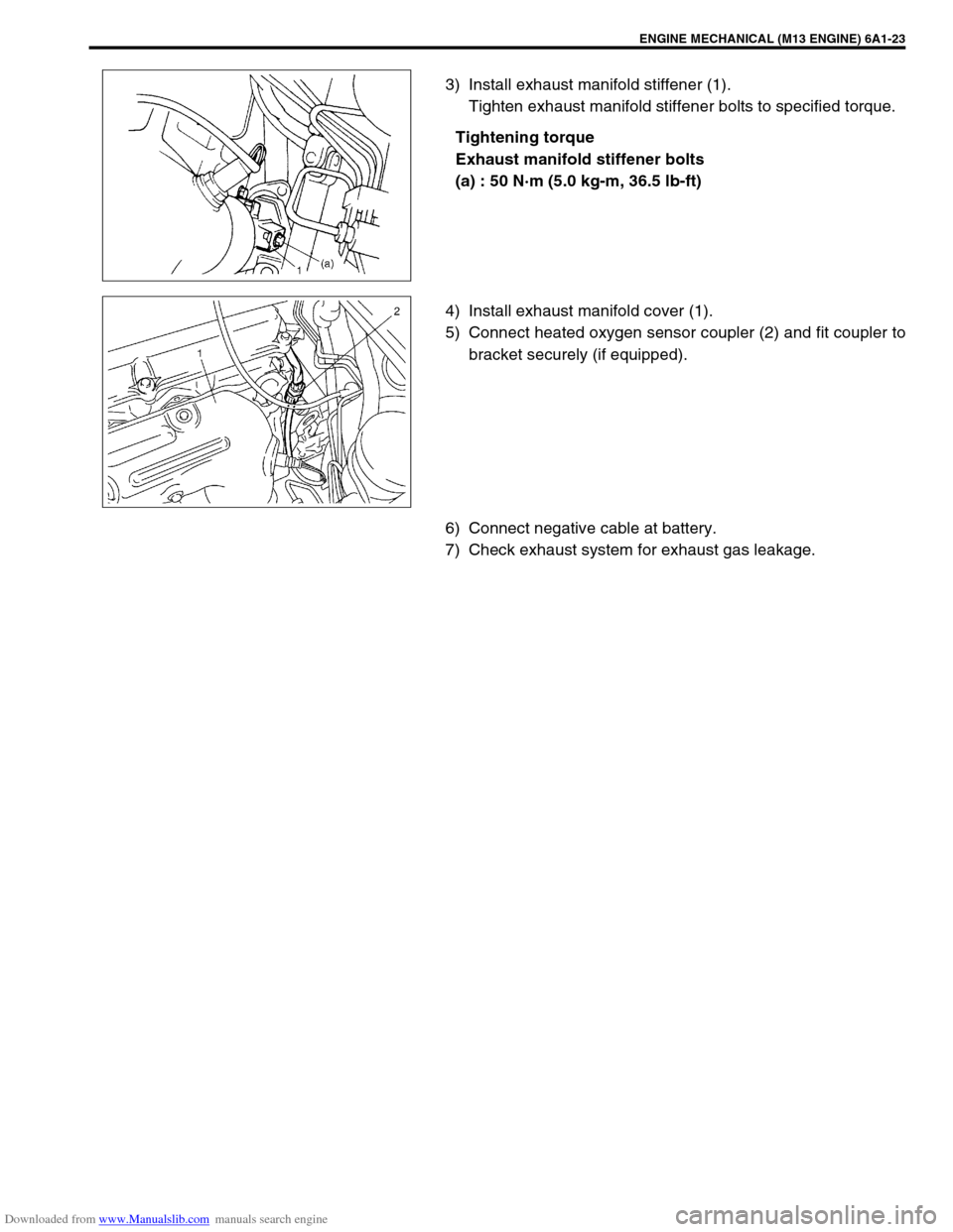
3) Install exhaust manifold stiffener (1).
Tighten exhaust manifold stiffener bolts to specified torque.
Tightening torque
Exhaust manifold stiffener bolts
(a) : 50 N·m (5.0 kg-m, 36.5 lb-ft)
4) Install exhaust manifold cover (1).
5) Connect heated oxygen sensor coupler (2) and fit coupler to
bracket securely (if equipped).
6) Connect negative cable at battery.
7) Check exhaust system for exhaust gas leakage.
Page 511 of 687
Downloaded from www.Manualslib.com manuals search engine 6A1-30 ENGINE MECHANICAL (M13 ENGINE)
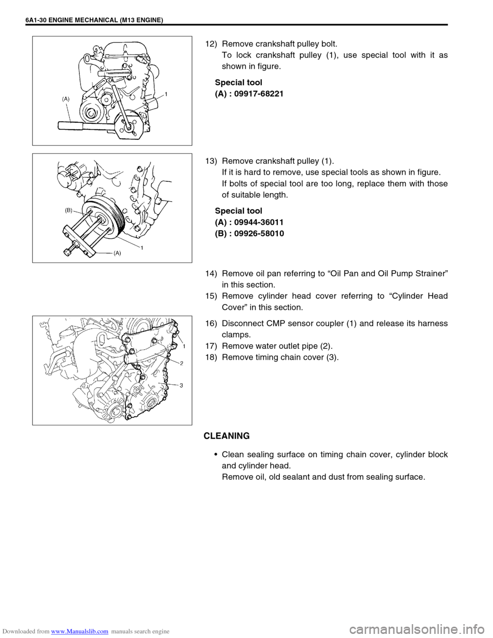
12) Remove crankshaft pulley bolt.
To lock crankshaft pulley (1), use special tool with it as
shown in figure.
Special tool
(A) : 09917-68221
13) Remove crankshaft pulley (1).
If it is hard to remove, use special tools as shown in figure.
If bolts of special tool are too long, replace them with those
of suitable length.
Special tool
(A) : 09944-36011
(B) : 09926-58010
14) Remove oil pan referring to “Oil Pan and Oil Pump Strainer”
in this section.
15) Remove cylinder head cover referring to “Cylinder Head
Cover” in this section.
16) Disconnect CMP sensor coupler (1) and release its harness
clamps.
17) Remove water outlet pipe (2).
18) Remove timing chain cover (3).
CLEANING
Clean sealing surface on timing chain cover, cylinder block
and cylinder head.
Remove oil, old sealant and dust from sealing surface.
Page 530 of 687
Downloaded from www.Manualslib.com manuals search engine ENGINE MECHANICAL (M13 ENGINE) 6A1-49
REMOVAL
1) Relieve fuel pressure referring to “Fuel Pressure Relief Pro-
cedure” in Section 6.
2) Disconnect negative cable at battery.
3) Drain engine oil.
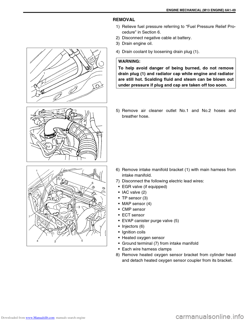
4) Drain coolant by loosening drain plug (1).
5) Remove air cleaner outlet No.1 and No.2 hoses and
breather hose.
6) Remove intake manifold bracket (1) with main harness from
intake manifold.
7) Disconnect the following electric lead wires:
EGR valve (if equipped)
IAC valve (2)
TP sensor (3)
MAP sensor (4)
CMP sensor
ECT sensor
EVAP canister purge valve (5)
Injectors (6)
Ignition coils
Heated oxygen sensor
Ground terminal (7) from intake manifold
Each wire harness clamps
8) Remove heated oxygen sensor bracket from cylinder head
and detach heated oxygen sensor coupler from its bracket. WARNING:
To help avoid danger of being burned, do not remove
drain plug (1) and radiator cap while engine and radiator
are still hot. Scalding fluid and steam can be blown out
under pressure if plug and cap are taken off too soon.
Page 555 of 687
Downloaded from www.Manualslib.com manuals search engine 6A1-74 ENGINE MECHANICAL (M13 ENGINE)
a) For right hand steering vehicle:
With hose connected, detach A/C compressor from its
bracket.
b) For left hand steering vehicle:
i) Recover refrigerant from refrigeration system using recov-
ery and recycling equipment.
ii) Disconnect magnet clutch lead wire.
iii) Remove suction pipe and disconnect discharge pipe from
A/C compressor.
iv) Remove A/C compressor from its bracket.
When servicing above steps, refer to “Compressor” in Section 1B.
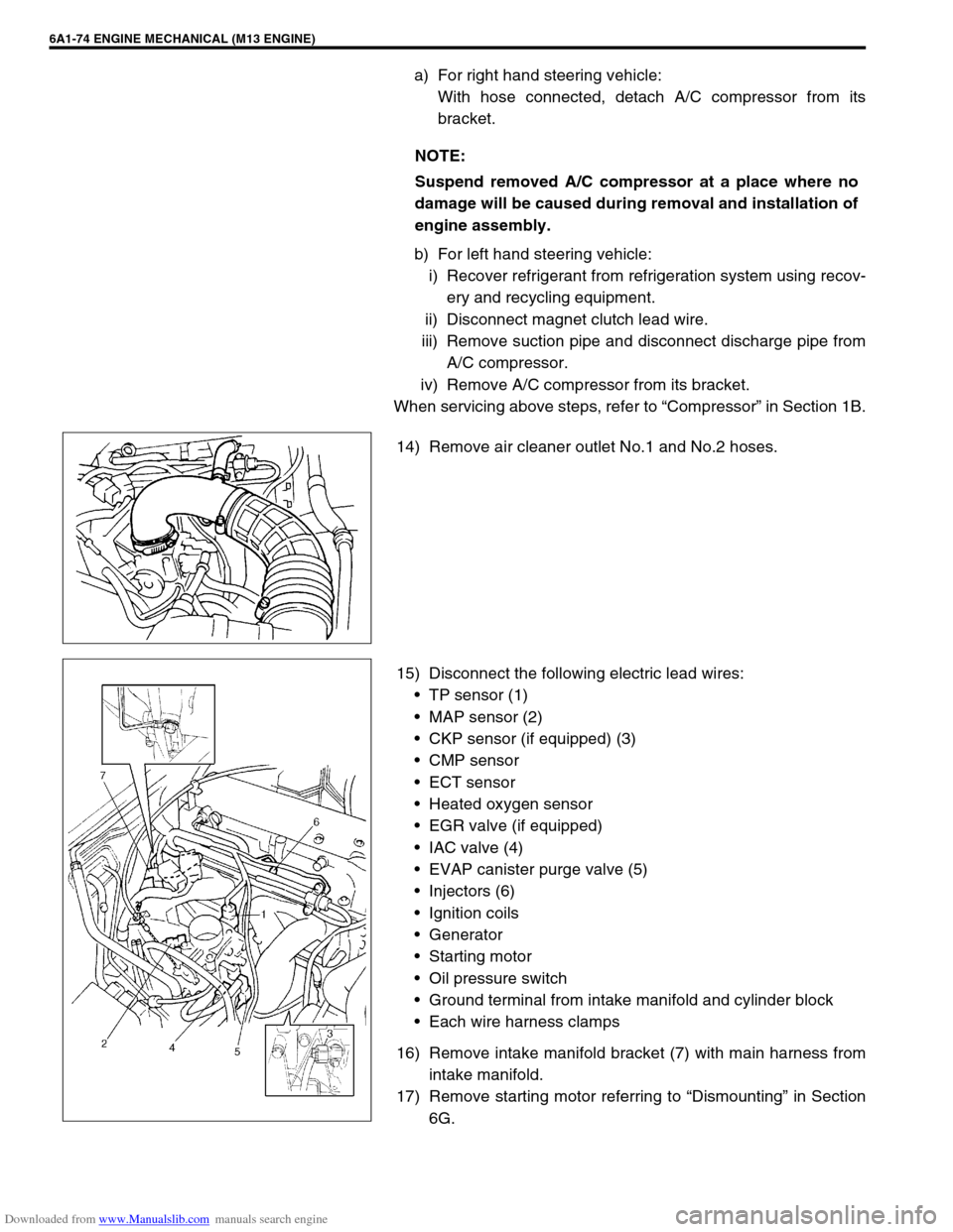
14) Remove air cleaner outlet No.1 and No.2 hoses.
15) Disconnect the following electric lead wires:
TP sensor (1)
MAP sensor (2)
CKP sensor (if equipped) (3)
CMP sensor
ECT sensor
Heated oxygen sensor
EGR valve (if equipped)
IAC valve (4)
EVAP canister purge valve (5)
Injectors (6)
Ignition coils
Generator
Starting motor
Oil pressure switch
Ground terminal from intake manifold and cylinder block
Each wire harness clamps
16) Remove intake manifold bracket (7) with main harness from
intake manifold.
17) Remove starting motor referring to “Dismounting” in Section
6G. NOTE:
Suspend removed A/C compressor at a place where no
damage will be caused during removal and installation of
engine assembly.
Page 556 of 687
Downloaded from www.Manualslib.com manuals search engine ENGINE MECHANICAL (M13 ENGINE) 6A1-75
18) Remove heated oxygen sensor bracket from cylinder head
and detach No.1 heated oxygen sensor coupler from its
bracket.
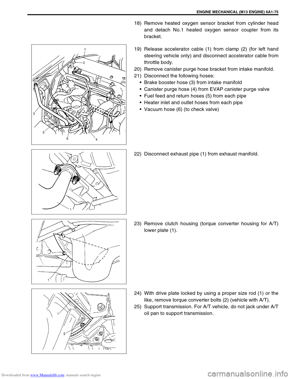
19) Release accelerator cable (1) from clamp (2) (for left hand
steering vehicle only) and disconnect accelerator cable from
throttle body.
20) Remove canister purge hose bracket from intake manifold.
21) Disconnect the following hoses:
Brake booster hose (3) from intake manifold
Canister purge hose (4) from EVAP canister purge valve
Fuel feed and return hoses (5) from each pipe
Heater inlet and outlet hoses from each pipe
Vacuum hose (6) (to check valve)
22) Disconnect exhaust pipe (1) from exhaust manifold.
23) Remove clutch housing (torque converter housing for A/T)
lower plate (1).
24) With drive plate locked by using a proper size rod (1) or the
like, remove torque converter bolts (2) (vehicle with A/T).
25) Support transmission. For A/T vehicle, do not jack under A/T
oil pan to support transmission.
Page 560 of 687
Downloaded from www.Manualslib.com manuals search engine ENGINE MECHANICAL (M13 ENGINE) 6A1-79
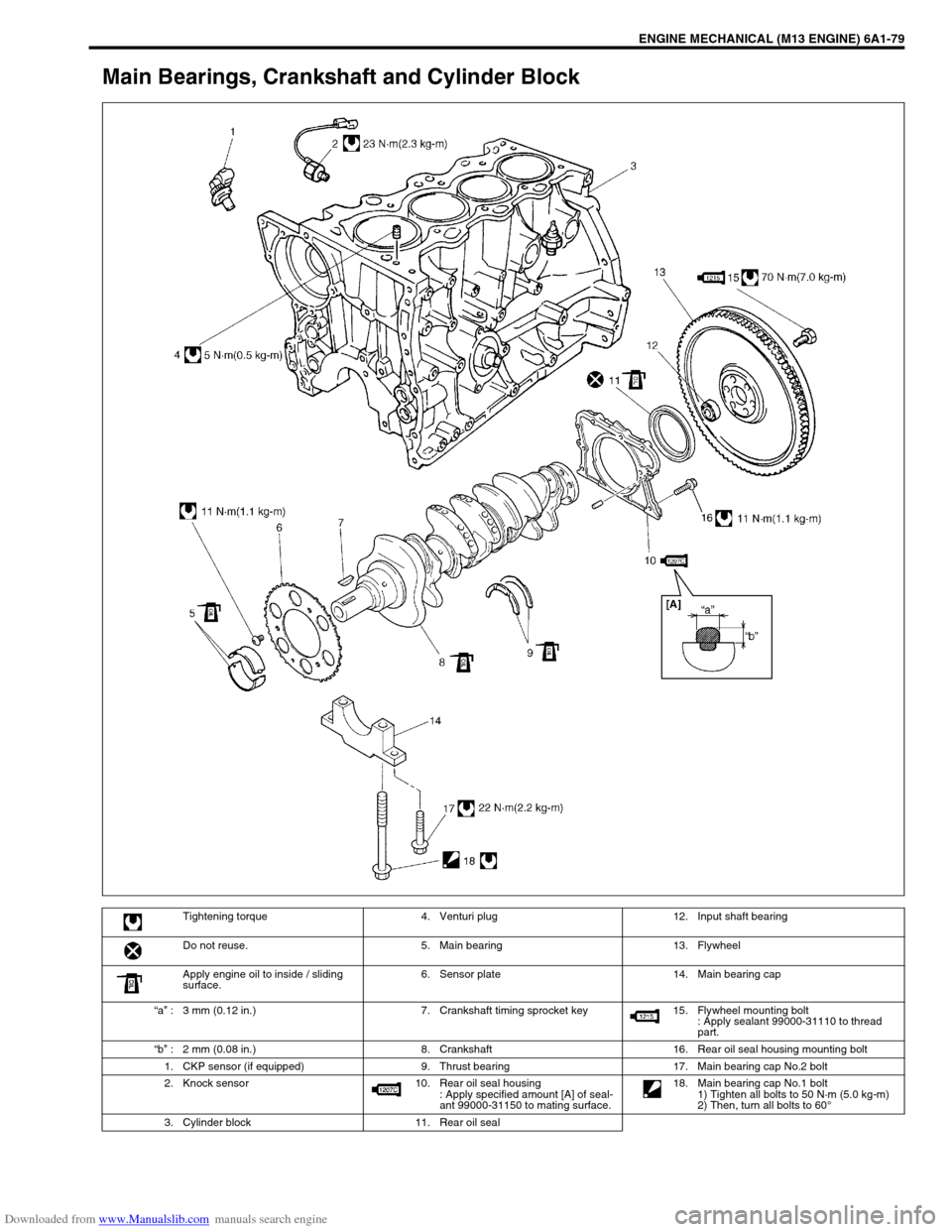
Main Bearings, Crankshaft and Cylinder Block
Tightening torque 4. Venturi plug 12. Input shaft bearing
Do not reuse. 5. Main bearing 13. Flywheel
Apply engine oil to inside / sliding
surface.6. Sensor plate 14. Main bearing cap
“a” : 3 mm (0.12 in.) 7. Crankshaft timing sprocket key 15. Flywheel mounting bolt
: Apply sealant 99000-31110 to thread
part.
“b” : 2 mm (0.08 in.) 8. Crankshaft 16. Rear oil seal housing mounting bolt
1. CKP sensor (if equipped) 9. Thrust bearing 17. Main bearing cap No.2 bolt
2. Knock sensor 10. Rear oil seal housing
: Apply specified amount [A] of seal-
ant 99000-31150 to mating surface. 18. Main bearing cap No.1 bolt
1) Tighten all bolts to 50 N·m (5.0 kg-m)
2) Then, turn all bolts to 60°
3. Cylinder block 11. Rear oil seal
Page 569 of 687
Downloaded from www.Manualslib.com manuals search engine 6A1-88 ENGINE MECHANICAL (M13 ENGINE)
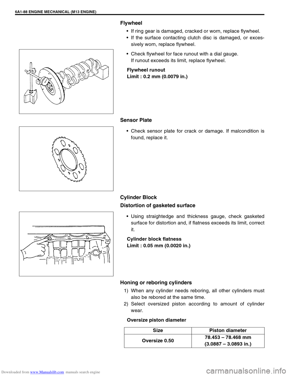
Flywheel
If ring gear is damaged, cracked or worn, replace flywheel.
If the surface contacting clutch disc is damaged, or exces-
sively worn, replace flywheel.
Check flywheel for face runout with a dial gauge.
If runout exceeds its limit, replace flywheel.
Flywheel runout
Limit : 0.2 mm (0.0079 in.)
Sensor Plate
Check sensor plate for crack or damage. If malcondition is
found, replace it.
Cylinder Block
Distortion of gasketed surface
Using straightedge and thickness gauge, check gasketed
surface for distortion and, if flatness exceeds its limit, correct
it.
Cylinder block flatness
Limit : 0.05 mm (0.0020 in.)
Honing or reboring cylinders
1) When any cylinder needs reboring, all other cylinders must
also be rebored at the same time.
2) Select oversized piston according to amount of cylinder
wear.
Oversize piston diameter
Size Piston diameter
Oversize 0.5078.453 – 78.468 mm
(3.0887 – 3.0893 in.)
Page 571 of 687
Downloaded from www.Manualslib.com manuals search engine 6A1-90 ENGINE MECHANICAL (M13 ENGINE)
INSTALLATION
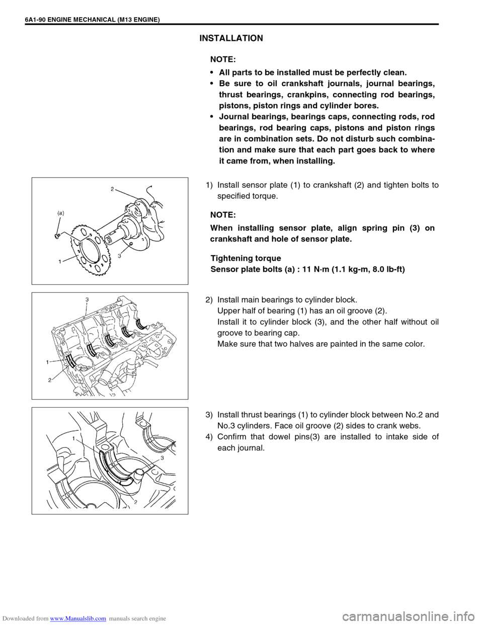
1) Install sensor plate (1) to crankshaft (2) and tighten bolts to
specified torque.
Tightening torque
Sensor plate bolts (a) : 11 N·m (1.1 kg-m, 8.0 lb-ft)
2) Install main bearings to cylinder block.
Upper half of bearing (1) has an oil groove (2).
Install it to cylinder block (3), and the other half without oil
groove to bearing cap.
Make sure that two halves are painted in the same color.
3) Install thrust bearings (1) to cylinder block between No.2 and
No.3 cylinders. Face oil groove (2) sides to crank webs.
4) Confirm that dowel pins(3) are installed to intake side of
each journal. NOTE:
All parts to be installed must be perfectly clean.
Be sure to oil crankshaft journals, journal bearings,
thrust bearings, crankpins, connecting rod bearings,
pistons, piston rings and cylinder bores.
Journal bearings, bearings caps, connecting rods, rod
bearings, rod bearing caps, pistons and piston rings
are in combination sets. Do not disturb such combina-
tion and make sure that each part goes back to where
it came from, when installing.
NOTE:
When installing sensor plate, align spring pin (3) on
crankshaft and hole of sensor plate.
Page 575 of 687
Downloaded from www.Manualslib.com manuals search engine 6A1-94 ENGINE MECHANICAL (M13 ENGINE)
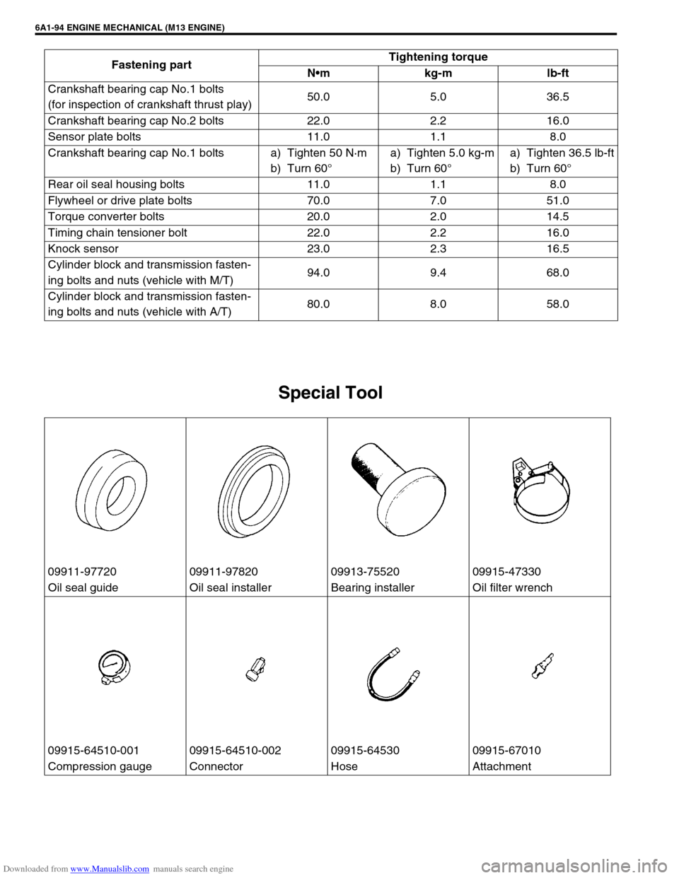
Special Tool
Crankshaft bearing cap No.1 bolts
(for inspection of crankshaft thrust play)50.0 5.0 36.5
Crankshaft bearing cap No.2 bolts 22.0 2.2 16.0
Sensor plate bolts 11.0 1.1 8.0
Crankshaft bearing cap No.1 bolts a) Tighten 50 N·m
b) Turn 60°a) Tighten 5.0 kg-m
b) Turn 60°a) Tighten 36.5 lb-ft
b) Turn 60°
Rear oil seal housing bolts 11.0 1.1 8.0
Flywheel or drive plate bolts 70.0 7.0 51.0
Torque converter bolts 20.0 2.0 14.5
Timing chain tensioner bolt 22.0 2.2 16.0
Knock sensor 23.0 2.3 16.5
Cylinder block and transmission fasten-
ing bolts and nuts (vehicle with M/T)94.0 9.4 68.0
Cylinder block and transmission fasten-
ing bolts and nuts (vehicle with A/T)80.0 8.0 58.0 Fastening partTightening torque
Nm kg-m lb-ft
09911-97720 09911-97820 09913-75520 09915-47330
Oil seal guide Oil seal installer Bearing installer Oil filter wrench
09915-64510-001 09915-64510-002 09915-64530 09915-67010
Compression gauge Connector Hose Attachment
Page 587 of 687
Downloaded from www.Manualslib.com manuals search engine 6B-10 ENGINE COOLING
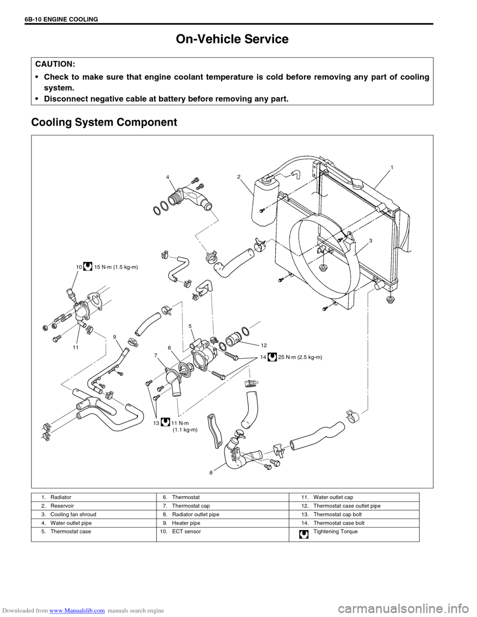
On-Vehicle Service
Cooling System Component
CAUTION:
Check to make sure that engine coolant temperature is cold before removing any part of cooling
system.
Disconnect negative cable at battery before removing any part.
1. Radiator 6. Thermostat 11. Water outlet cap
2. Reservoir 7. Thermostat cap 12. Thermostat case outlet pipe
3. Cooling fan shroud 8. Radiator outlet pipe 13. Thermostat cap bolt
4. Water outlet pipe 9. Heater pipe 14. Thermostat case bolt
5. Thermostat case 10. ECT sensor Tightening Torque
814 25 N·m (2.5 kg-m) 10 15 N·m (1.5 kg-m)
12 5
6
7
13 11 N·m
(1.1 kg-m) 119421
3