cooling SUZUKI JIMNY 2005 3.G Service User Guide
[x] Cancel search | Manufacturer: SUZUKI, Model Year: 2005, Model line: JIMNY, Model: SUZUKI JIMNY 2005 3.GPages: 687, PDF Size: 13.38 MB
Page 71 of 687

Downloaded from www.Manualslib.com manuals search engine 1B-10 AIR CONDITIONING (OPTIONAL)
Performance Diagnosis
1) Confirm that vehicle and environmental conditions are as fol-
lows.
Vehicle is not exposed to direct sun.
Ambient temperature is within 15 – 35 °C (59 – 95 °F).
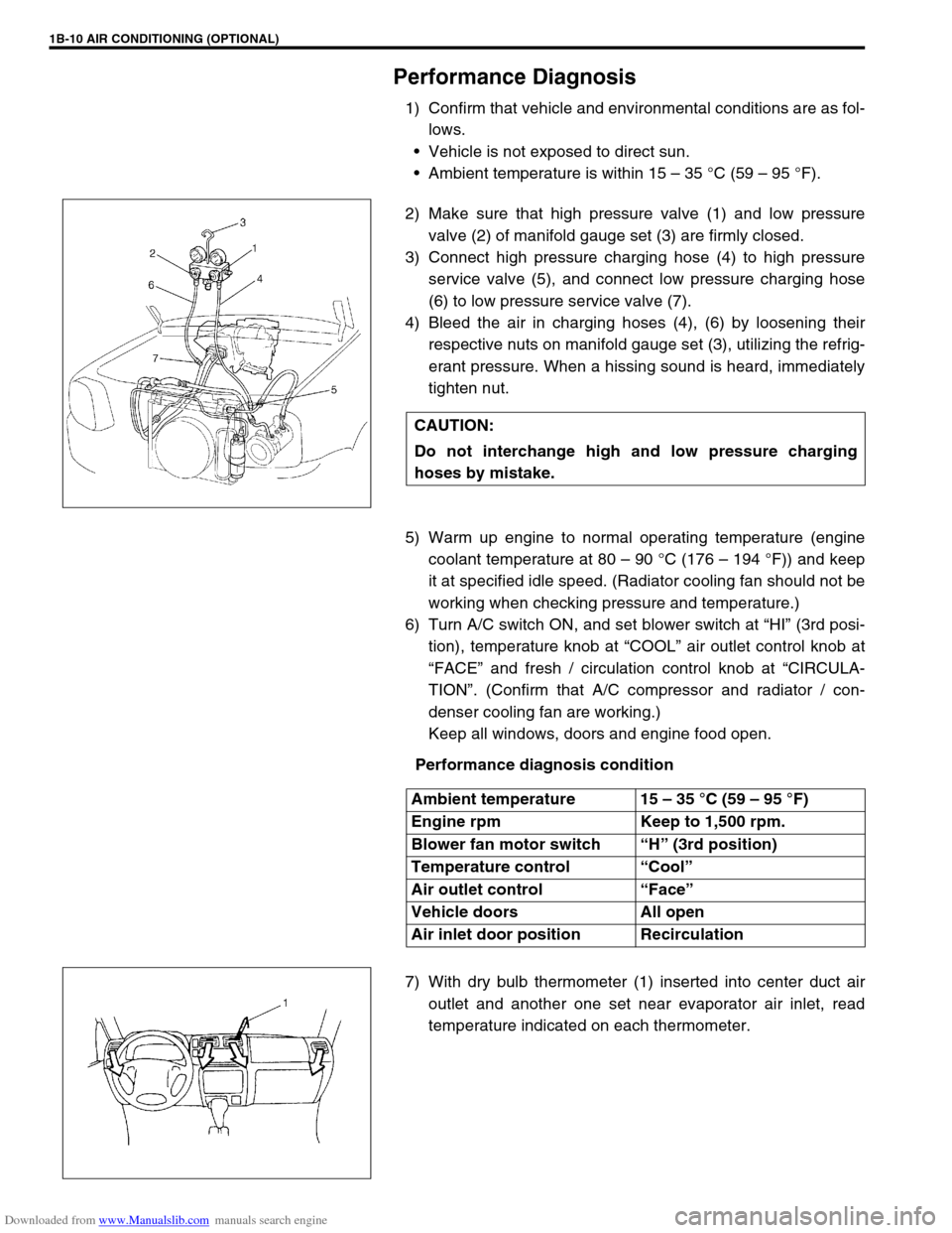
2) Make sure that high pressure valve (1) and low pressure
valve (2) of manifold gauge set (3) are firmly closed.
3) Connect high pressure charging hose (4) to high pressure
service valve (5), and connect low pressure charging hose
(6) to low pressure service valve (7).
4) Bleed the air in charging hoses (4), (6) by loosening their
respective nuts on manifold gauge set (3), utilizing the refrig-
erant pressure. When a hissing sound is heard, immediately
tighten nut.
5) Warm up engine to normal operating temperature (engine
coolant temperature at 80 – 90 °C (176 – 194 °F)) and keep
it at specified idle speed. (Radiator cooling fan should not be
working when checking pressure and temperature.)
6) Turn A/C switch ON, and set blower switch at “HI” (3rd posi-
tion), temperature knob at “COOL” air outlet control knob at
“FACE” and fresh / circulation control knob at “CIRCULA-
TION”. (Confirm that A/C compressor and radiator / con-
denser cooling fan are working.)
Keep all windows, doors and engine food open.
Performance diagnosis condition
7) With dry bulb thermometer (1) inserted into center duct air
outlet and another one set near evaporator air inlet, read
temperature indicated on each thermometer. CAUTION:
Do not interchange high and low pressure charging
hoses by mistake.
Ambient temperature 15 – 35 °C (59 – 95 °F)
Engine rpm Keep to 1,500 rpm.
Blower fan motor switch “H” (3rd position)
Temperature control “Cool”
Air outlet control “Face”
Vehicle doors All open
Air inlet door position Recirculation
Page 73 of 687

Downloaded from www.Manualslib.com manuals search engine 1B-12 AIR CONDITIONING (OPTIONAL)
Performance diagnosis table
HIGH PRESSURE GAUGE
LOW PRESSURE GAUGE
NOTE:
If ambient temperature is approximately 30 °C (86 °F), it is possible to diagnose A/C system in detail
referring to “Detail Diagnosis Table (Ambient Temperature At 30 °C (86 °F))” under “Performance
Diagnosis” in this section.
Condition Possible Cause Correction
Pressure in higher
than acceptable range
(“A” area)Refrigerant overcharged Recharge
Expansion valve frozen or clogged Check expansion valve
Clogged refrigerant passage of high side Clean or replace
Condenser cooling fan malfunction (Insufficient
cooling of condenser)Check condenser cooling fan
Dirty or bent condenser fins (Insufficient cooling
of condenser)Clean or repair
Compressor malfunction (Insufficient oil etc.) Check compressor
Engine overheat Check engine cooling system refer-
ring to Section 6B.
Pressure is lower than
acceptable range
(“B” area)Insufficient refrigerant (Insufficient charge or
leakage)Check for leakage, repair if neces-
sary and recharge
Expansion valve malfunction (valve opens too
wide)Check expansion valve
Compressor malfunction (Insufficient compres-
sion)Check compressor
Condition Possible Cause Correction
Pressure is higher
than acceptable range
(“C” area)Expansion valve malfunction (valve opens too
wide)Check expansion valve
Compressor malfunction (Insufficient compres-
sion)Check compressor
Pressure is lower than
acceptable range
(“D” area)Insufficient refrigerant (Insufficient charge or
leakage)Check for leakage, repair if neces-
sary and recharge
Expansion valve malfunction (valve opens too
narrow)Check expansion valve
Clogged refrigerant passage (crashed pipe) Repair or replace
Page 74 of 687

Downloaded from www.Manualslib.com manuals search engine AIR CONDITIONING (OPTIONAL) 1B-13
CROSSING POINT OF CENTER VENTILATION LOUVER TEMPERATURE AND RECIRCULATION AIR
INLET TEMPERATURE
Detail diagnosis table (Ambient temperature at 30°C (86°F))
Condition Possible Cause Correction
Crossing point is
higher than accept-
able range
(“E” area)Insufficient or excessive charge of refrigerant Check refrigerant pressure
Dirty or bent A/C evaporator fins Clean or repair
Air leakage from cooling (heater) unit or air duct Repair or replace
Malfunctioning, switch over function of door in
cooling (heater) unitRepair or replace
Compressor malfunction Check compressor
Crossing point is
lower than acceptable
range
(“F” area)Insufficient air volume from center duct (Heater
blower malfunction)Check blower motor and fan
Compressor malfunction Check compressor
Condition
Possible Cause Correction MANIFOLD
GAUGEMPa
(kg/cm
2)
(psi)Detail
Lo Hi
0.23 – 0.35
(2.3 – 3.5)
(33 – 50)1.4 – 1.75
(14 – 17.5)
(200 – 249)Normal condition
––
Negative
pressure0.5 – 0.6
(5 – 6)
(71.2 – 85.3)The low pressure side
reads a negative pres-
sure, and the high pres-
sure side reads an
extremely low pressure.
Presence of frost
around tubing to and
from receiver / dryer
and expansion valve.Dust particles or water
droplets are either stuck
or frozen inside expan-
sion valve, preventing the
refrigerant from flowing.Clean expansion valve.
Replace it if it cannot be
cleaned.
Replace receiver / dryer.
Evacuate the A/C sys-
tem and recharge with
fresh refrigerant.
Normal :
0.23 – 0.35
(2.3 – 3.5)
(33 – 50)
↑
↑ ↑ ↑ ↓
↓↓ ↓
Abnormal :
Negative
pressureNormal :
1.4 – 1.75
(14 – 17.5)
(200 – 249)
↑
↑ ↑ ↑ ↓
↓↓ ↓
Abnormal :
0.69 – 0.98
(7 – 10)
(100 – 142)During A/C operation,
the low pressure side
sometimes indicates
negative pressure, and
sometimes normal
pressure. Also high
pressure side reading
fluctuates between the
abnormal and normal
pressure.Expansion valve is frozen
due to moisture in the
system, and temporarily
shuts off the refrigeration
cycle.Replace expansion valve.
Replace receiver / dryer.
Evacuate A/C system
and recharge with fresh
refrigerant.
Page 75 of 687

Downloaded from www.Manualslib.com manuals search engine 1B-14 AIR CONDITIONING (OPTIONAL)
0.05 – 0.15
(0.5 – 1.5)
(4.2 – 21.3)
0.69 – 0.98
(7 – 10)
(100 – 142)Both low and high pres-
sure sides indicate low
readings.
Continuous air bub-
bles are visible through
sight glass.
Output air is slightly
cold.Insufficient refrigerant in
system.
(Refrigerant leaking)Using leak detector,
check for leaks and repair
as necessary.
Recharge refrigerant to a
specified amount.
If the pressure reading is
almost 0 when the mani-
fold gauges are attached,
check for any leaks,
repair them, and evacu-
ate the system.
0.4 – 0.6
(4 – 6)
(56.9 – 85.3)Pressure on low pres-
sure side is high.
Pressure on high pres-
sure side is low.
Both pressure becom-
ing equal right after A/C
is turned OFF.Internal leak in compres-
sor.Inspect compressor and
repair or replace as nec-
essary.
0.35 – 0.45
(3.5 – 4.5)
(50 – 64)
1.96 – 2.45
(20 – 25)
(285 – 355)Pressure on both low
and high pressure
sides is high.
Air bubbles are not visi-
ble even when engine
rpm is lowered.Overcharged A/C sys-
tem.Adjust refrigerant to
specified amount.
Faulty condenser cooling
operation.Clean condenser.
Faulty condenser cooling
fan operation.Inspect and repair con-
denser cooling fan.
Pressure on both low
and high pressure
sides is high.
Low pressure side tub-
ing is not cold when
touched.
Air bubbles are visible
through sight glass.Presence of air in A/C
system.
(Improperly evacuated)Replace receiver / dryer.
Inspect quantity of com-
pressor oil and presence
of contaminants in oil.
Evacuate system and
recharge with fresh
refrigerant.
0.45 – 0.55
(4.5 – 5.5)
(64 – 78)Pressure on both low
and high pressure
sides is high.
Large amount of frost
or dew on the low pres-
sure side tubing.Faulty expansion valve.
Refrigerant flow is not
regulated properly.Replace expansion valve. Condition
Possible Cause Correction MANIFOLD
GAUGEMPa
(kg/cm
2)
(psi)Detail
Lo Hi
Page 77 of 687
![SUZUKI JIMNY 2005 3.G Service User Guide Downloaded from www.Manualslib.com manuals search engine 1B-16 AIR CONDITIONING (OPTIONAL)
Electronical Diagnosis
Wiring Diagram
[A]: 4WD model 4. Dual pressure switch 9. Thermal switch 14. Circuit fu SUZUKI JIMNY 2005 3.G Service User Guide Downloaded from www.Manualslib.com manuals search engine 1B-16 AIR CONDITIONING (OPTIONAL)
Electronical Diagnosis
Wiring Diagram
[A]: 4WD model 4. Dual pressure switch 9. Thermal switch 14. Circuit fu](/img/20/7588/w960_7588-76.png)
Downloaded from www.Manualslib.com manuals search engine 1B-16 AIR CONDITIONING (OPTIONAL)
Electronical Diagnosis
Wiring Diagram
[A]: 4WD model 4. Dual pressure switch 9. Thermal switch 14. Circuit fuse box
[B]: 2WD model 5. 4WD controller 10. Ignition switch 15. Main fuse box
1. Blower fan motor 6. Condenser cooling fan motor relay 11. A/C evaporator thermistor 16. Generator
2. Blower fan motor resistor 7. Condenser cooling fan motor 12. ECT sensor 17. ECM
3. Blower fan motor switch and A/C switch 8. Compressor 13. Lighting switch
Page 79 of 687
![SUZUKI JIMNY 2005 3.G Service User Guide Downloaded from www.Manualslib.com manuals search engine 1B-18 AIR CONDITIONING (OPTIONAL)
Terminal arrangement of ECM coupler (Viewed from harness side)
1. Blower fan motor 8. Compressor [A]: To “A SUZUKI JIMNY 2005 3.G Service User Guide Downloaded from www.Manualslib.com manuals search engine 1B-18 AIR CONDITIONING (OPTIONAL)
Terminal arrangement of ECM coupler (Viewed from harness side)
1. Blower fan motor 8. Compressor [A]: To “A](/img/20/7588/w960_7588-78.png)
Downloaded from www.Manualslib.com manuals search engine 1B-18 AIR CONDITIONING (OPTIONAL)
Terminal arrangement of ECM coupler (Viewed from harness side)
1. Blower fan motor 8. Compressor [A]: To “A/C” fuse (25A) in main fuse box
2. Dual pressure switch 9. Thermal switch [B]: To “HEATER” fuse (20A) in circuit fuse box
3. A/C switch 10. Main relay [C]: To “FI” fuse (15A) in main fuse box
4. A/C evaporator thermistor 11. Engine earth [D]: 4WD model
5. ECT sensor 12. Blower fan motor switch [E]: 2WD model
6. Condenser cooling fan motor relay 13. 4WD controller
7. Condenser cooling fan motor 14. ECM
Page 80 of 687

Downloaded from www.Manualslib.com manuals search engine AIR CONDITIONING (OPTIONAL) 1B-19
ECM VOLTAGE VALUES TABLE FOR RELATION OF A/C CONTROL
Terminal Wire CircuitMeasurement
groundNormal value Condition
E18-1 PCompressor
magnet clutch
outputGround to
engine (Fig B)10 – 14 voltBlower fan motor switch and A/C
switch ON with engine running
0 – 1 voltsExcept the above-mentioned condi-
tion with engine running
E18-5 Bl/BMain power sup-
ply for ECMGround to
engine (Fig B)10 – 14 voltsIgnition switch ON with engine
stopped
E18-6 Bl/BMain power sup-
ply for ECMGround to
engine (Fig B)10 – 14 voltsIgnition switch ON with engine
stopped
E18-10 Bl Main relay driveGround to
engine (Fig B)0.5 – 1.2 voltIgnition switch ON with engine
stopped
0 volts Ignition switch OFF
E18-16 G/W A/C switch inputGround to
engine (Fig B)12 – 15 voltsBlower fan motor switch or A/C switch
OFF with engine running
0 – 1 voltBlower fan motor switch and A/C
switch ON with engine running
12 – 15 voltsWithin several seconds after operate
transfer lever between 2WD and 4WD
with above condition
E18-18 P/BCompressor
cooling fan relay
outputGround to
engine (Fig B)0 – 1 voltBlower fan motor switch and A/C
switch ON or engine coolant tempera-
ture at more than 110 °C (230 °F) with
engine running.
12 – 15 voltsExcept the above-mentioned condi-
tion with engine running
E18-20 B/BlSensor ground
for A/C evapora-
torGround to
body (Fig A)–0.5 – 0 volt Engine running
E18-24 Bl/YBlower fan
speed inputGround to
engine (Fig B)0 – 1 voltBlower fan motor switch 2nd or 3rd
with engine running
4 – 7 voltsBlower fan motor switch 1st with
engine running
12 – 15 voltsBlower fan motor switch and A/C
switch OFF with engine running
E19-1 BMain ground for
ECMGround to
engine (Fig A)–0.5 – 1 volt Engine running
E19-2 B/RECM ground for
power circuitGround to
engine (Fig A)–0.5 – 1 volt Engine running
E19-3 B/RECM ground for
power circuitGround to
engine (Fig A)–0.5 – 1 volt Engine running
E19-10 B/BlSensor ground
for ECT sensorGround to
body (Fig A)–0.5 – 1 volt Engine running
Page 81 of 687

Downloaded from www.Manualslib.com manuals search engine 1B-20 AIR CONDITIONING (OPTIONAL)
E19-14 G/BECT sensor
inputGround to
engine (Fig B)0.73 – 0.83 volts
(315 – 355 Ω)Engine coolant temperature at
approximately 80 °C (176 °F) with
engine running
0.35 – 0.45 volts
(145 – 165 Ω)Engine coolant temperature at
approximately 110 °C (230 °F) with
engine running
*If the temperature is more than
113 °C (235 °F), compressor should
be stop (come back at less than
111 °C (232 °F)
E19-27 W/RA/C evaporator
thermistor tem-
perature inputGround to
engine (Fig B)2.0 – 2.3 volts
(1800 – 2200 Ω)Evaporator thermistor temperature at
approximately 25 °C (77 °F) with
engine running
3.5 – 3.6 volts
(6300 – 7000 Ω)Evaporator thermistor temperature at
approximately 0 °C (32 °F) with
engine running
*If the temperature is less than
approximately 2.5 °C (36.5 °F), com-
pressor cooling fan should be stop
(come back at less than approxi-
mately 4 °C (39.2 °F) Terminal Wire CircuitMeasurement
groundNormal value Condition
Page 92 of 687

Downloaded from www.Manualslib.com manuals search engine AIR CONDITIONING (OPTIONAL) 1B-31
Condenser Assembly
INSPECTION
Check the following.
Check clog of condenser fins.
If, any clogs are found, condenser fins should be washed
with water, and should be dried with compressed air.
Check condenser fins for leakage and breakage.
If any defects are found, repair or replace condenser.
Check condenser fittings for leakage.
If any defects are found, repair or replace condenser.
REMOVAL
1) Disconnect negative (–) cable at battery.
2) Recover refrigerant from A/C system by referring to “Recov-
ery” in this section.
3) Remove front bumper referring to “Front Bumper” in Section
8.
4) Disconnect A/C condenser cooling fan motor and dual pres-
sure switch connectors.
5) Remove radiator mounting bolts.
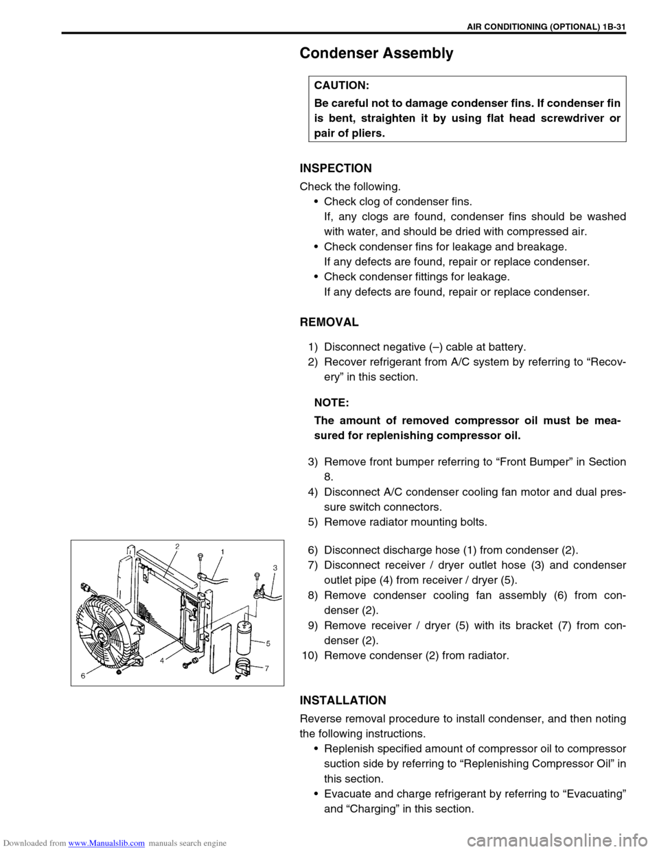
6) Disconnect discharge hose (1) from condenser (2).
7) Disconnect receiver / dryer outlet hose (3) and condenser
outlet pipe (4) from receiver / dryer (5).
8) Remove condenser cooling fan assembly (6) from con-
denser (2).
9) Remove receiver / dryer (5) with its bracket (7) from con-
denser (2).
10) Remove condenser (2) from radiator.
INSTALLATION
Reverse removal procedure to install condenser, and then noting
the following instructions.
Replenish specified amount of compressor oil to compressor
suction side by referring to “Replenishing Compressor Oil” in
this section.
Evacuate and charge refrigerant by referring to “Evacuating”
and “Charging” in this section. CAUTION:
Be careful not to damage condenser fins. If condenser fin
is bent, straighten it by using flat head screwdriver or
pair of pliers.
NOTE:
The amount of removed compressor oil must be mea-
sured for replenishing compressor oil.
Page 94 of 687

Downloaded from www.Manualslib.com manuals search engine AIR CONDITIONING (OPTIONAL) 1B-33
Condenser Cooling Fan Assembly
ASSEMBLY
INSPECTION
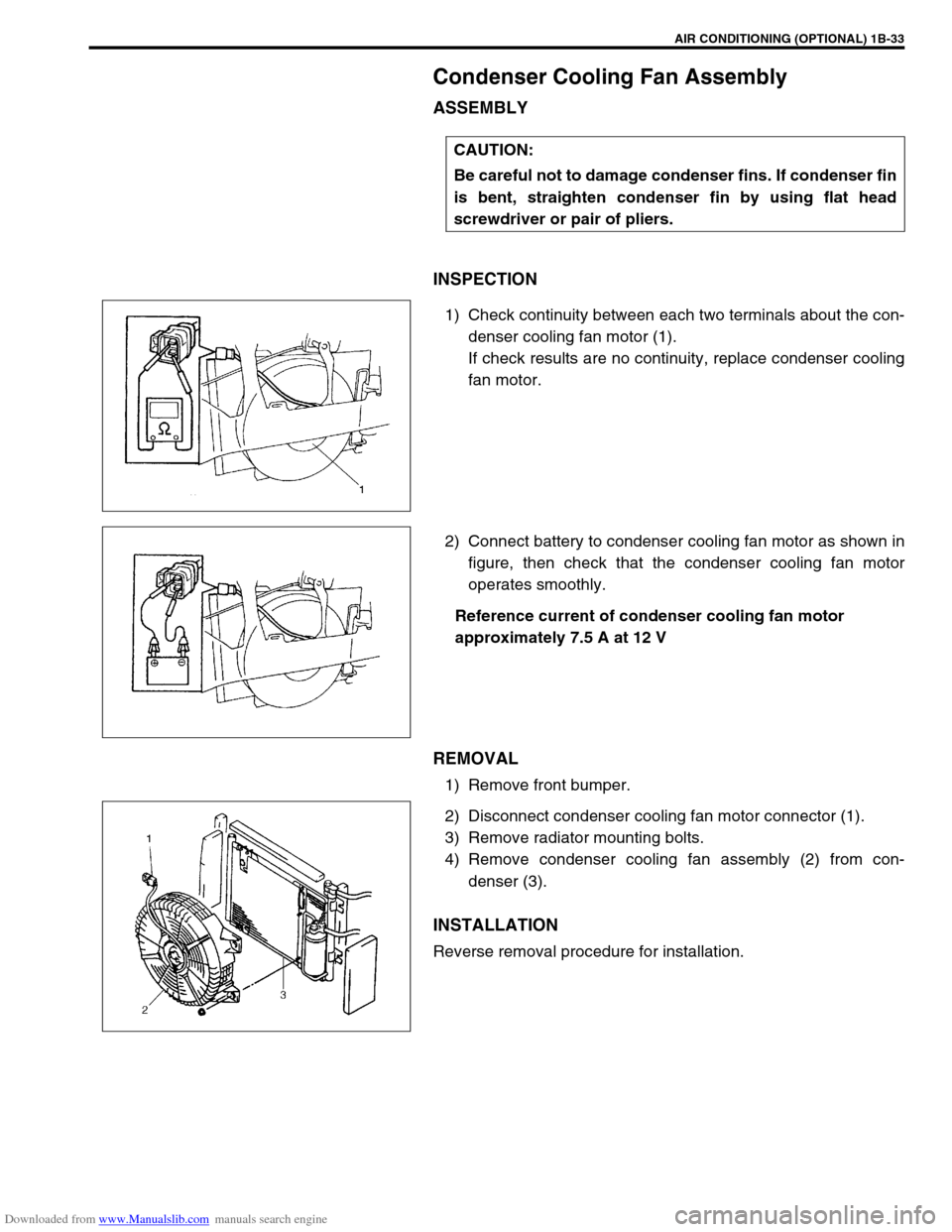
1) Check continuity between each two terminals about the con-
denser cooling fan motor (1).
If check results are no continuity, replace condenser cooling
fan motor.
2) Connect battery to condenser cooling fan motor as shown in
figure, then check that the condenser cooling fan motor
operates smoothly.
Reference current of condenser cooling fan motor
approximately 7.5 A at 12 V
REMOVAL
1) Remove front bumper.
2) Disconnect condenser cooling fan motor connector (1).
3) Remove radiator mounting bolts.
4) Remove condenser cooling fan assembly (2) from con-
denser (3).
INSTALLATION
Reverse removal procedure for installation.CAUTION:
Be careful not to damage condenser fins. If condenser fin
is bent, straighten condenser fin by using flat head
screwdriver or pair of pliers.