timing SUZUKI JIMNY 2005 3.G Service User Guide
[x] Cancel search | Manufacturer: SUZUKI, Model Year: 2005, Model line: JIMNY, Model: SUZUKI JIMNY 2005 3.GPages: 687, PDF Size: 13.38 MB
Page 509 of 687
Downloaded from www.Manualslib.com manuals search engine 6A1-28 ENGINE MECHANICAL (M13 ENGINE)
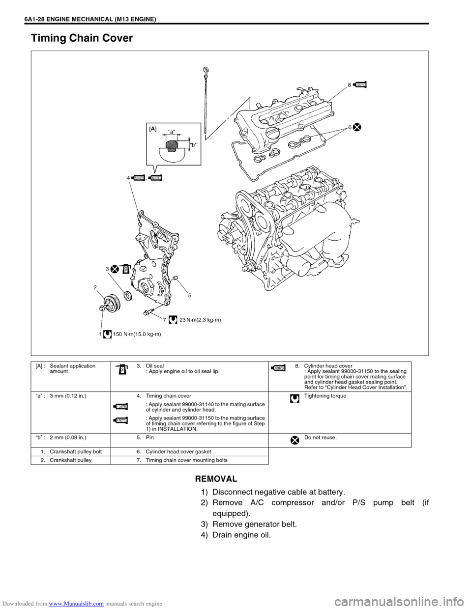
Timing Chain Cover
REMOVAL
1) Disconnect negative cable at battery.
2) Remove A/C compressor and/or P/S pump belt (if
equipped).
3) Remove generator belt.
4) Drain engine oil.
[A] : Sealant application
amount3. Oil seal
: Apply engine oil to oil seal lip.8. Cylinder head cover
: Apply sealant 99000-31150 to the sealing
point for timing chain cover mating surface
and cylinder head gasket sealing point.
Refer to “Cylinder Head Cover Installation”.
“a” : 3 mm (0.12 in.) 4. Timing chain cover Tightening torque
: Apply sealant 99000-31140 to the mating surface
of cylinder and cylinder head.
: Apply sealant 99000-31150 to the mating surface
of timing chain cover referring to the figure of Step
1) in INSTALLATION.
“b” : 2 mm (0.08 in.) 5. Pin Do not reuse.
1. Crankshaft pulley bolt 6. Cylinder head cover gasket
2. Crankshaft pulley 7. Timing chain cover mounting bolts
Page 510 of 687
Downloaded from www.Manualslib.com manuals search engine ENGINE MECHANICAL (M13 ENGINE) 6A1-29
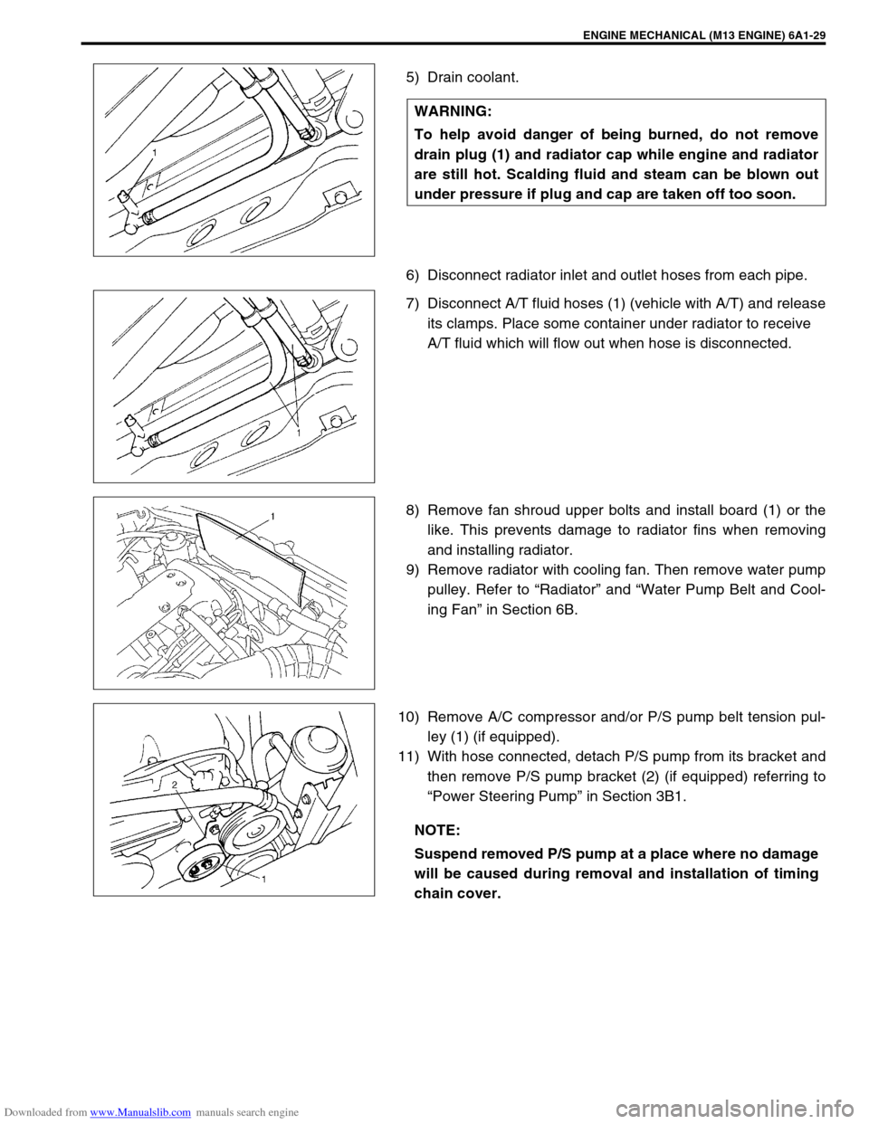
5) Drain coolant.
6) Disconnect radiator inlet and outlet hoses from each pipe.
7) Disconnect A/T fluid hoses (1) (vehicle with A/T) and release
its clamps. Place some container under radiator to receive
A/T fluid which will flow out when hose is disconnected.
8) Remove fan shroud upper bolts and install board (1) or the
like. This prevents damage to radiator fins when removing
and installing radiator.
9) Remove radiator with cooling fan. Then remove water pump
pulley. Refer to “Radiator” and “Water Pump Belt and Cool-
ing Fan” in Section 6B.
10) Remove A/C compressor and/or P/S pump belt tension pul-
ley (1) (if equipped).
11) With hose connected, detach P/S pump from its bracket and
then remove P/S pump bracket (2) (if equipped) referring to
“Power Steering Pump” in Section 3B1. WARNING:
To help avoid danger of being burned, do not remove
drain plug (1) and radiator cap while engine and radiator
are still hot. Scalding fluid and steam can be blown out
under pressure if plug and cap are taken off too soon.
NOTE:
Suspend removed P/S pump at a place where no damage
will be caused during removal and installation of timing
chain cover.
Page 511 of 687
Downloaded from www.Manualslib.com manuals search engine 6A1-30 ENGINE MECHANICAL (M13 ENGINE)
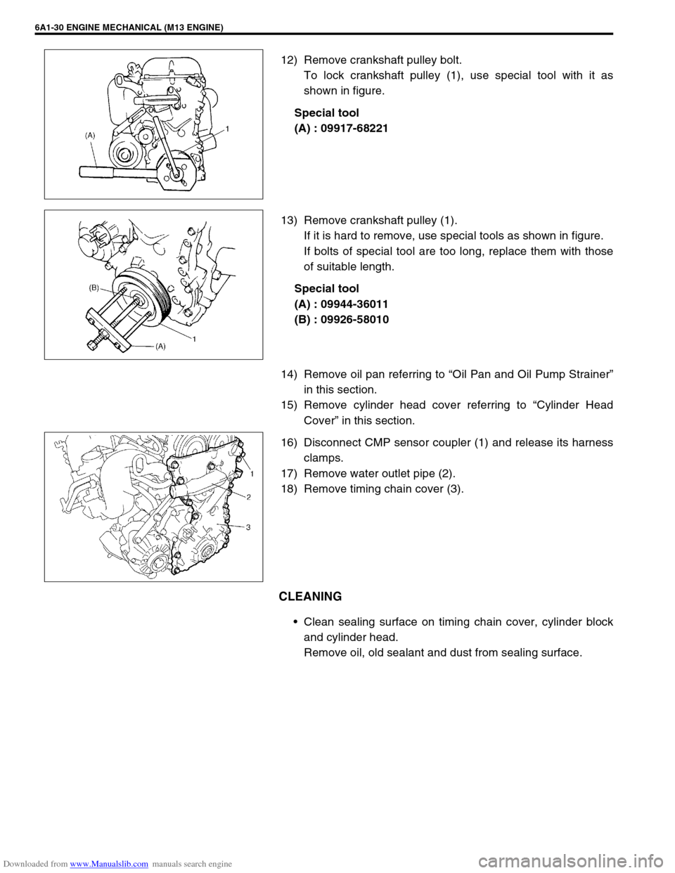
12) Remove crankshaft pulley bolt.
To lock crankshaft pulley (1), use special tool with it as
shown in figure.
Special tool
(A) : 09917-68221
13) Remove crankshaft pulley (1).
If it is hard to remove, use special tools as shown in figure.
If bolts of special tool are too long, replace them with those
of suitable length.
Special tool
(A) : 09944-36011
(B) : 09926-58010
14) Remove oil pan referring to “Oil Pan and Oil Pump Strainer”
in this section.
15) Remove cylinder head cover referring to “Cylinder Head
Cover” in this section.
16) Disconnect CMP sensor coupler (1) and release its harness
clamps.
17) Remove water outlet pipe (2).
18) Remove timing chain cover (3).
CLEANING
Clean sealing surface on timing chain cover, cylinder block
and cylinder head.
Remove oil, old sealant and dust from sealing surface.
Page 512 of 687
Downloaded from www.Manualslib.com manuals search engine ENGINE MECHANICAL (M13 ENGINE) 6A1-31
INSPECTION
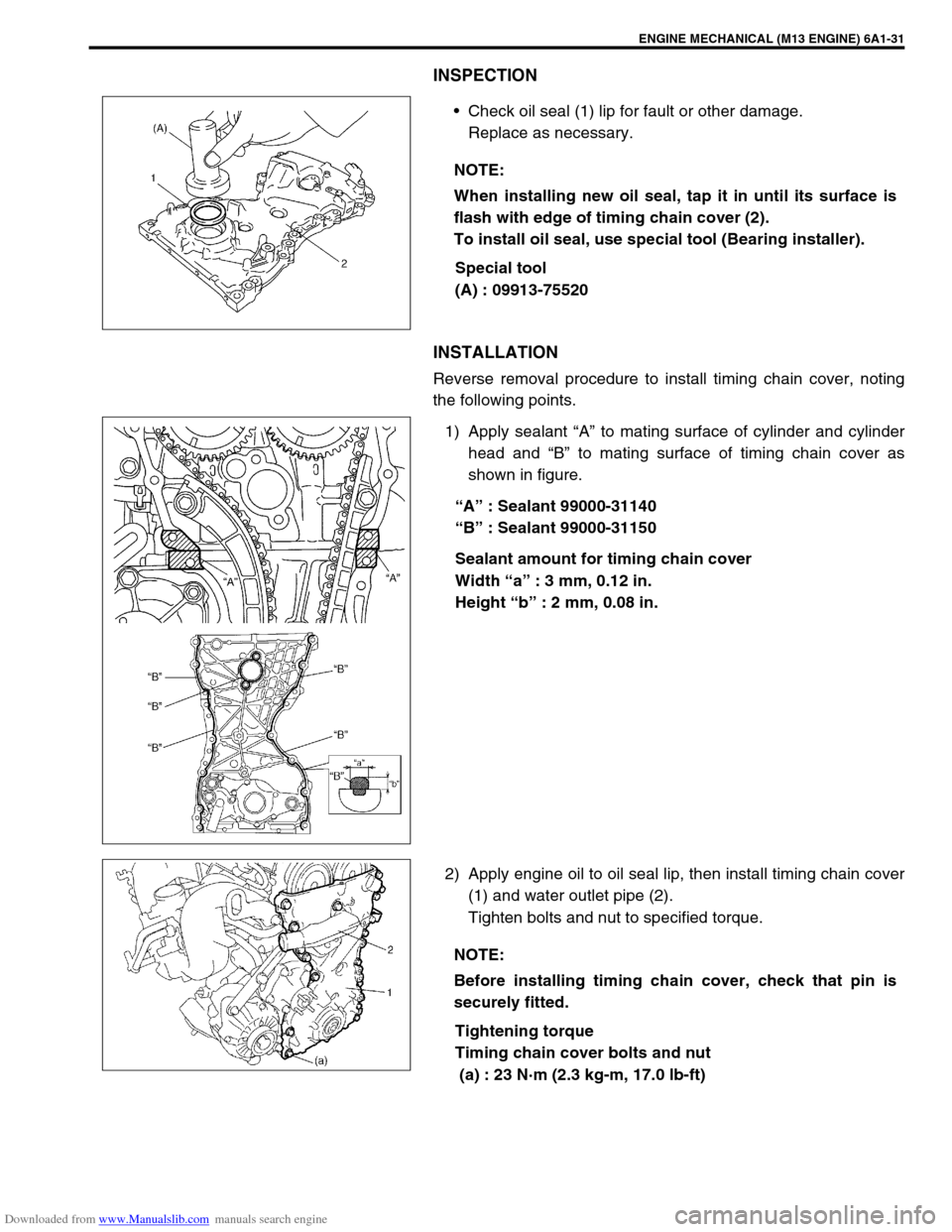
Check oil seal (1) lip for fault or other damage.
Replace as necessary.
Special tool
(A) : 09913-75520
INSTALLATION
Reverse removal procedure to install timing chain cover, noting
the following points.
1) Apply sealant “A” to mating surface of cylinder and cylinder
head and “B” to mating surface of timing chain cover as
shown in figure.
“A” : Sealant 99000-31140
“B” : Sealant 99000-31150
Sealant amount for timing chain cover
Width “a” : 3 mm, 0.12 in.
Height “b” : 2 mm, 0.08 in.
2) Apply engine oil to oil seal lip, then install timing chain cover
(1) and water outlet pipe (2).
Tighten bolts and nut to specified torque.
Tightening torque
Timing chain cover bolts and nut
(a) : 23 N·m (2.3 kg-m, 17.0 lb-ft) NOTE:
When installing new oil seal, tap it in until its surface is
flash with edge of timing chain cover (2).
To install oil seal, use special tool (Bearing installer).
NOTE:
Before installing timing chain cover, check that pin is
securely fitted.
Page 514 of 687
Downloaded from www.Manualslib.com manuals search engine ENGINE MECHANICAL (M13 ENGINE) 6A1-33
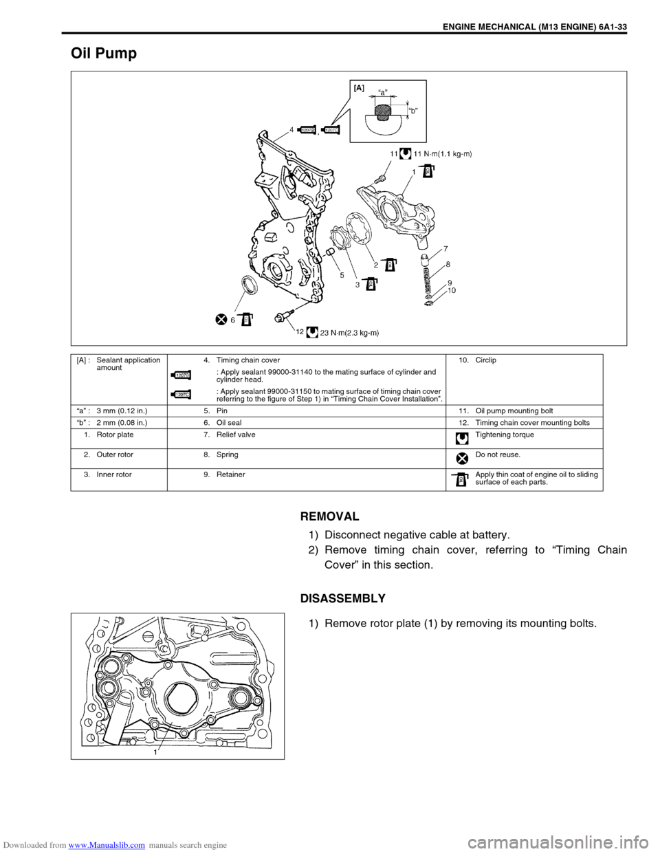
Oil Pump
REMOVAL
1) Disconnect negative cable at battery.
2) Remove timing chain cover, referring to “Timing Chain
Cover” in this section.
DISASSEMBLY
1) Remove rotor plate (1) by removing its mounting bolts.
[A] : Sealant application
amount4. Timing chain cover 10. Circlip
: Apply sealant 99000-31140 to the mating surface of cylinder and
cylinder head.
: Apply sealant 99000-31150 to mating surface of timing chain cover
referring to the figure of Step 1) in “Timing Chain Cover Installation”.
“a” : 3 mm (0.12 in.) 5. Pin 11. Oil pump mounting bolt
“b” : 2 mm (0.08 in.) 6. Oil seal 12. Timing chain cover mounting bolts
1. Rotor plate 7. Relief valve Tightening torque
2. Outer rotor 8. Spring Do not reuse.
3. Inner rotor 9. Retainer Apply thin coat of engine oil to sliding
surface of each parts.
Page 517 of 687
Downloaded from www.Manualslib.com manuals search engine 6A1-36 ENGINE MECHANICAL (M13 ENGINE)
ASSEMBLY
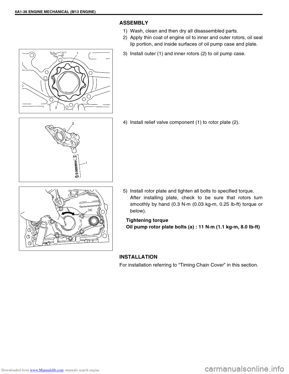
1) Wash, clean and then dry all disassembled parts.
2) Apply thin coat of engine oil to inner and outer rotors, oil seal
lip portion, and inside surfaces of oil pump case and plate.
3) Install outer (1) and inner rotors (2) to oil pump case.
4) Install relief valve component (1) to rotor plate (2).
5) Install rotor plate and tighten all bolts to specified torque.
After installing plate, check to be sure that rotors turn
smoothly by hand (0.3 N·m (0.03 kg-m, 0.25 lb-ft) torque or
below).
Tightening torque
Oil pump rotor plate bolts (a) : 11 N·m (1.1 kg-m, 8.0 lb-ft)
INSTALLATION
For installation referring to “Timing Chain Cover” in this section.
Page 518 of 687
Downloaded from www.Manualslib.com manuals search engine ENGINE MECHANICAL (M13 ENGINE) 6A1-37
Timing Chain and Chain Tensioner
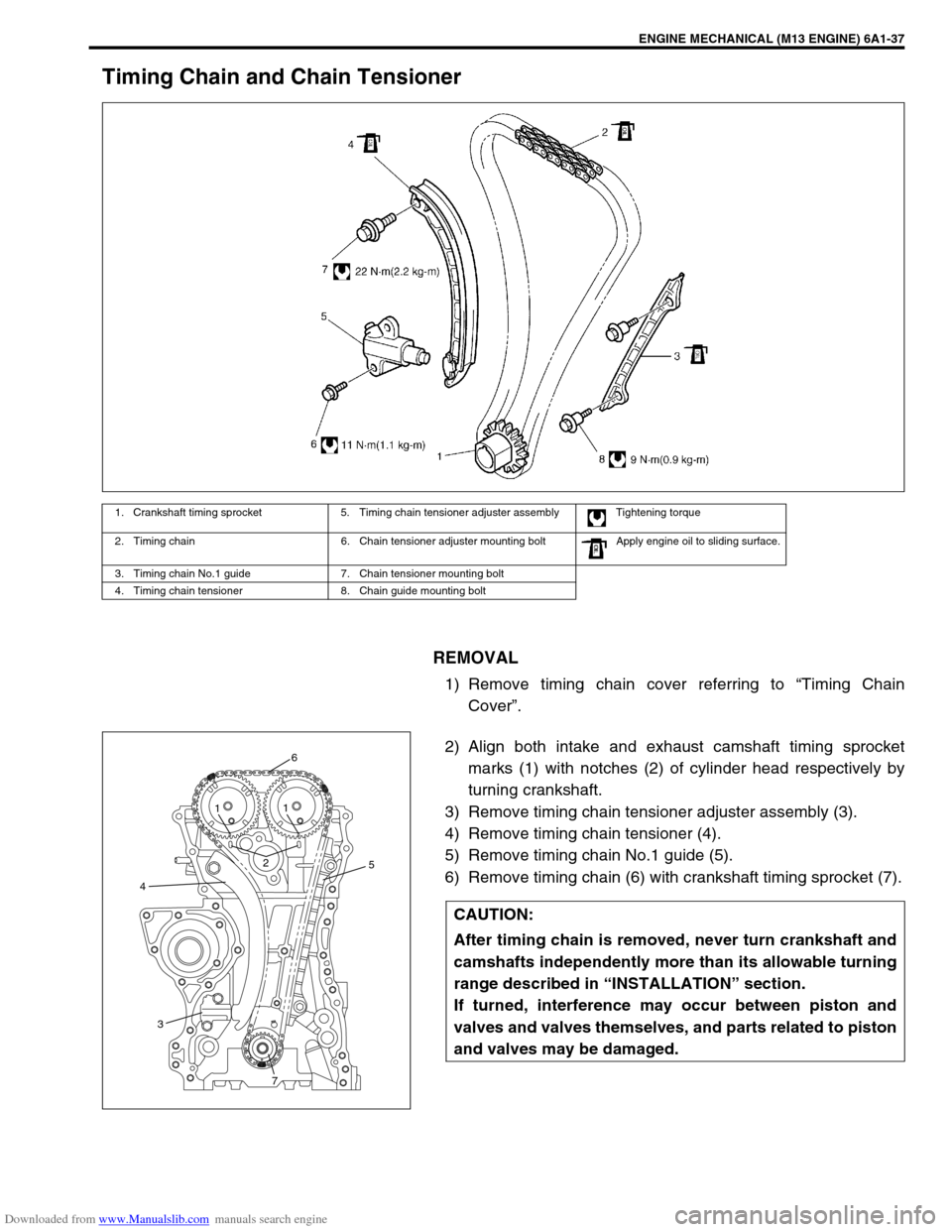
REMOVAL
1) Remove timing chain cover referring to “Timing Chain
Cover”.
2) Align both intake and exhaust camshaft timing sprocket
marks (1) with notches (2) of cylinder head respectively by
turning crankshaft.
3) Remove timing chain tensioner adjuster assembly (3).
4) Remove timing chain tensioner (4).
5) Remove timing chain No.1 guide (5).
6) Remove timing chain (6) with crankshaft timing sprocket (7).
1. Crankshaft timing sprocket 5. Timing chain tensioner adjuster assembly Tightening torque
2. Timing chain 6. Chain tensioner adjuster mounting bolt Apply engine oil to sliding surface.
3. Timing chain No.1 guide 7. Chain tensioner mounting bolt
4. Timing chain tensioner 8. Chain guide mounting bolt
CAUTION:
After timing chain is removed, never turn crankshaft and
camshafts independently more than its allowable turning
range described in “INSTALLATION” section.
If turned, interference may occur between piston and
valves and valves themselves, and parts related to piston
and valves may be damaged.
45
6
21
1
3
7
Page 519 of 687
Downloaded from www.Manualslib.com manuals search engine 6A1-38 ENGINE MECHANICAL (M13 ENGINE)
INSPECTION
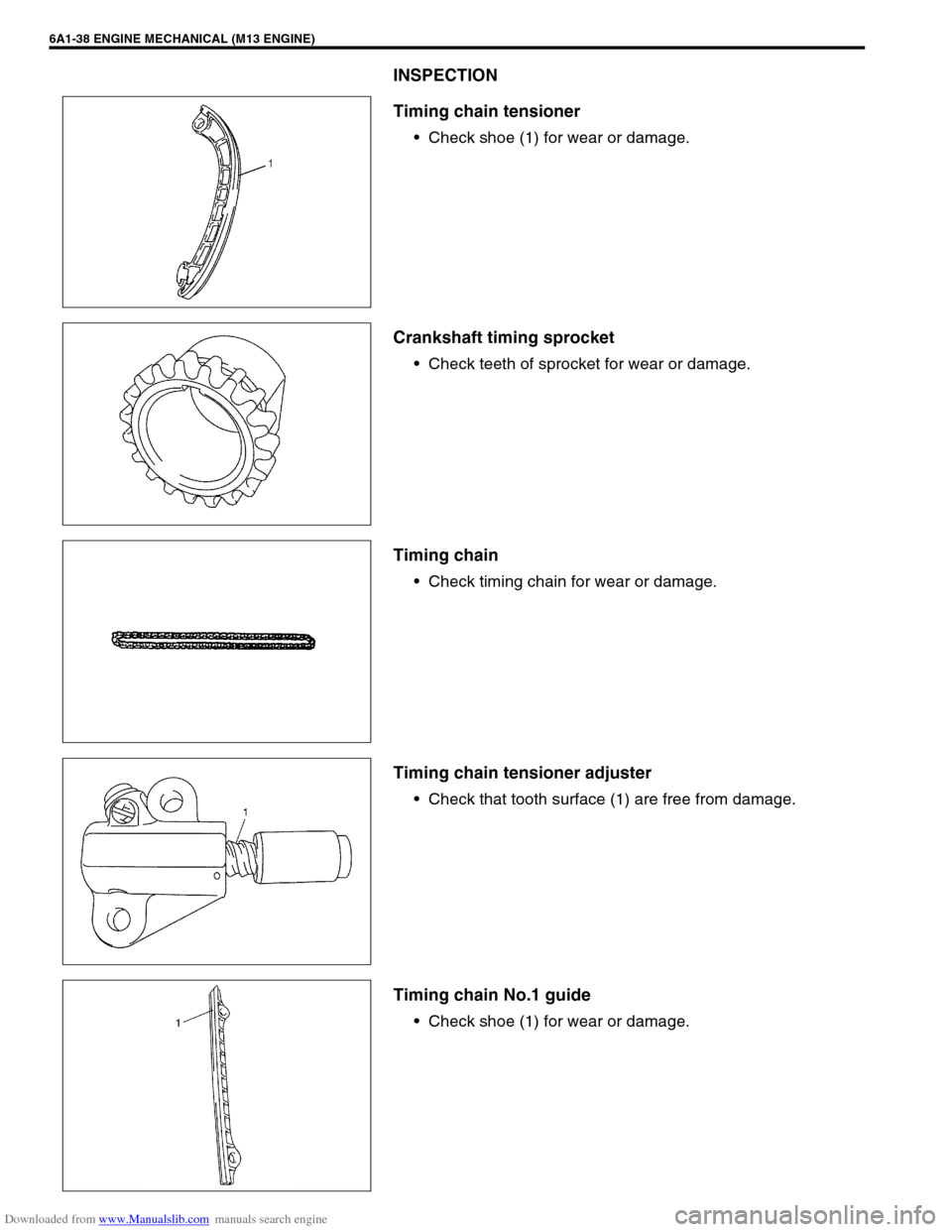
Timing chain tensioner
Check shoe (1) for wear or damage.
Crankshaft timing sprocket
Check teeth of sprocket for wear or damage.
Timing chain
Check timing chain for wear or damage.
Timing chain tensioner adjuster
Check that tooth surface (1) are free from damage.
Timing chain No.1 guide
Check shoe (1) for wear or damage.
Page 520 of 687
Downloaded from www.Manualslib.com manuals search engine ENGINE MECHANICAL (M13 ENGINE) 6A1-39
INSTALLATION
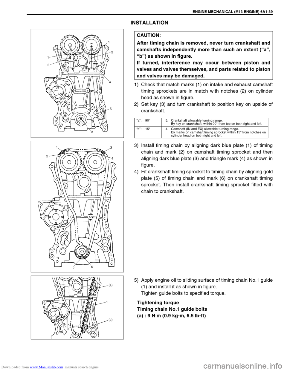
1) Check that match marks (1) on intake and exhaust camshaft
timing sprockets are in match with notches (2) on cylinder
head as shown in figure.
2) Set key (3) and turn crankshaft to position key on upside of
crankshaft.
3) Install timing chain by aligning dark blue plate (1) of timing
chain and mark (2) on camshaft timing sprocket and then
aligning dark blue plate (3) and triangle mark (4) as shown in
figure.
4) Fit crankshaft timing sprocket to timing chain by aligning gold
plate (5) of timing chain and mark (6) on crankshaft timing
sprocket. Then install crankshaft timing sprocket fitted with
chain to crankshaft.
5) Apply engine oil to sliding surface of timing chain No.1 guide
(1) and install it as shown in figure.
Tighten guide bolts to specified torque.
Tightening torque
Timing chain No.1 guide bolts
(a) : 9 N·m (0.9 kg-m, 6.5 lb-ft) CAUTION:
After timing chain is removed, never turn crankshaft and
camshafts independently more than such an extent (“a”,
“b”) as shown in figure.
If turned, interference may occur between piston and
valves and valves themselves, and parts related to piston
and valves may be damaged.
“a” :90°5. Crankshaft allowable turning range.
By key on crankshaft, within 90° from top on both right and left.
“b” :15°4. Camshaft (IN and EX) allowable turning range.
By marks on camshaft timing sprocket within 15° from notches on
cylinder head on both right and left.
Page 521 of 687
Downloaded from www.Manualslib.com manuals search engine 6A1-40 ENGINE MECHANICAL (M13 ENGINE)
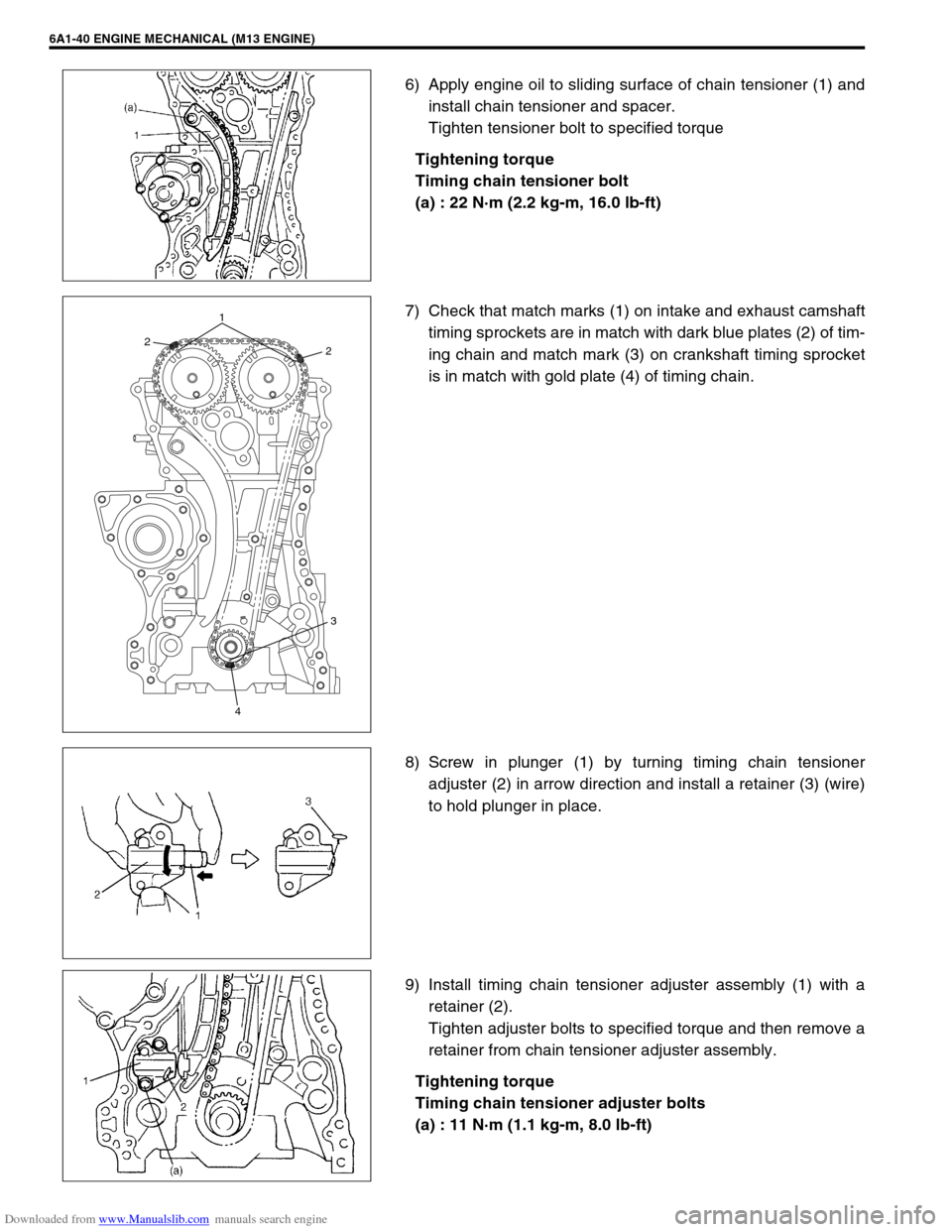
6) Apply engine oil to sliding surface of chain tensioner (1) and
install chain tensioner and spacer.
Tighten tensioner bolt to specified torque
Tightening torque
Timing chain tensioner bolt
(a) : 22 N·m (2.2 kg-m, 16.0 lb-ft)
7) Check that match marks (1) on intake and exhaust camshaft
timing sprockets are in match with dark blue plates (2) of tim-
ing chain and match mark (3) on crankshaft timing sprocket
is in match with gold plate (4) of timing chain.
8) Screw in plunger (1) by turning timing chain tensioner
adjuster (2) in arrow direction and install a retainer (3) (wire)
to hold plunger in place.
9) Install timing chain tensioner adjuster assembly (1) with a
retainer (2).
Tighten adjuster bolts to specified torque and then remove a
retainer from chain tensioner adjuster assembly.
Tightening torque
Timing chain tensioner adjuster bolts
(a) : 11 N·m (1.1 kg-m, 8.0 lb-ft)
221
3
4