ESP SUZUKI JIMNY 2005 3.G Service Owner's Manual
[x] Cancel search | Manufacturer: SUZUKI, Model Year: 2005, Model line: JIMNY, Model: SUZUKI JIMNY 2005 3.GPages: 687, PDF Size: 13.38 MB
Page 437 of 687

Downloaded from www.Manualslib.com manuals search engine 6-80 ENGINE GENERAL INFORMATION AND DIAGNOSIS
INSPECTION
Step Action Yes No
1Was “Engine Diag. Flow Table” performed? Go to Step 2. Go to “Engine Diag.
Flow Table”.
2 Check CKP Sensor and connector for proper
installation.
Is CKP sensor installed properly and connector
connected securely?Go to Step 3. Correct.
3 Check Wire Harness and Connection.
1) Disconnect connector from CKP sensor.
2) Check for proper connection to CKP sensor at
each terminal.
3) If OK, turn ignition switch ON and check for
voltage at each terminal of sensor connector
disconnected. See Fig. 1.
Terminal “B+” : 10 – 14 V
Terminal “Vout” : 4 – 5 V
Terminal “GND” : 0 V
Is check result satisfactory?Go to Step 5. Go to Step 4.
4 Was terminal “Vout” voltage out of specification in
Step 3 check?“G/R” wire open, short or
poor connection.
If wire and connection are
OK, substitute a known-
good ECM and recheck.“Bl/B” or “B/R” wire
open, short or poor
connection.
5 Check Ground Circuit for Open.
1) Turn ignition switch OFF.
2) Check for continuity between “GND” terminal
of CKP sensor connector and engine ground.
Is continuity indicated?Go to Step 6.“B/R” wire open or
poor ground connec-
tion.
6 Check CKP Sensor for Operation.
1) Remove CKP sensor from sensor case.
2) Remove metal particles on end face of CKP
sensor, if any.
3) Connect each connector to ECM and CKP
sensor.
4) Turn ignition switch ON.
5) Check for voltage at terminal E19-23 of con-
nector connected to ECM by passing magnetic
substance (iron) (1) while keeping approxi-
mately 1 mm (0.03 in.) gap with respect to end
face of CKP sensor. See Fig. 2 and 3.
Does voltage vary from low (0 – 1 V) to high (4 – 5
V) or from high to low?Go to Step 7. Replace CKP sensor.
7 Check signal rotor for the following. See Fig. 4.
Damage
No foreign material attached
Is it in good condition?Intermittent trouble or
faulty ECM.
Check for intermittent
referring to “Intermittent
and Poor Connection” in
Section 0A.Clean rotor teeth or
replace CKP sensor.
Page 440 of 687

Downloaded from www.Manualslib.com manuals search engine ENGINE GENERAL INFORMATION AND DIAGNOSIS 6-83
INSPECTION
Step Action Yes No
1Was “Engine Diag. Flow Table” performed? Go to Step 2. Go to “Engine Diag.
Flow Table”.
2 Check CMP Sensor and connector for proper installa-
tion.
Is CMP sensor installed properly and connector con-
nected securely?Go to Step 3. Correct.
3 Check Wire Harness and Connection.
1) Disconnect connector from CMP sensor.
2) Check for proper connection to CMP sensor at
each terminal.
3) If OK, turn ignition switch ON and check for volt-
age at each terminal of sensor connector discon-
nected. See Fig. 1.
Terminal “B+” : 10 – 14 V
Terminal “Vout” : 4 – 5 V
Terminal “GND” : 0 V
Is check result satisfactory?Go to Step 5. Go to Step 4.
4 Was terminal “Vout” voltage out of specification in
Step 3 check?“W” wire open, short or
poor connection.
If wire and connection
are OK, substitute a
known-good ECM and
recheck.“Bl/B” or “B/R” wire
open, short or poor
connection.
5 Check Ground Circuit for Open.
1) Turn ignition switch OFF.
2) Check for continuity between “GND” terminal of
CMP sensor connector and engine ground.
Is continuity indicated?Go to Step 6.“B/R” wire open or
poor ground connec-
tion.
6 Check CMP Sensor for Operation.
1) Remove CMP sensor from sensor case.
2) Remove metal particles on end face of CMP sen-
sor, if any.
3) Connect each connector to ECM and CMP sensor.
4) Turn ignition switch ON.
5) Check for voltage at terminal E19-11 of connector
connected to ECM by passing magnetic sub-
stance (iron) (1) while keeping approximately 1
mm (0.03 in.) gap with respect to end face of CMP
sensor. See Fig. 2 and 3.
Does voltage vary from low (0 – 1 V) to high (4 – 5 V)
or from high to low?Go to Step 7. Replace CMP sen-
sor.
7 Check signal rotor for the following.
See Fig. 4.
Damage
No foreign material attached
Is it in good condition?Intermittent trouble or
faulty ECM.
Check for intermittent
referring to “Intermittent
and Poor Connection” in
Section 0A.Clean rotor teeth or
replace CMP sensor.
Page 462 of 687
Downloaded from www.Manualslib.com manuals search engine ENGINE GENERAL INFORMATION AND DIAGNOSIS 6-105
DTC P1600 Serial Communication Problem Between ECM and TCM
CIRCUIT DESCRIPTION
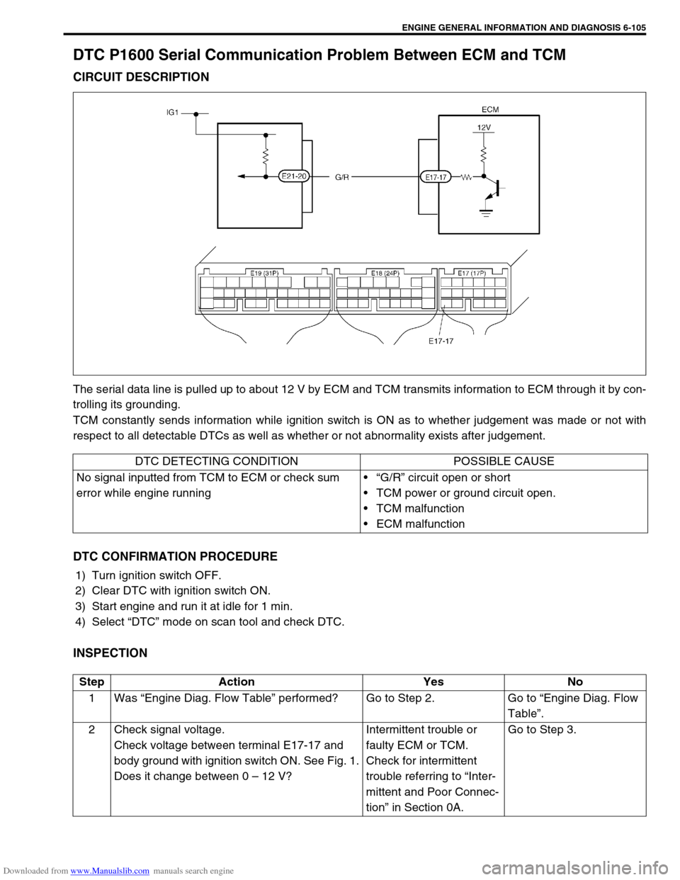
The serial data line is pulled up to about 12 V by ECM and TCM transmits information to ECM through it by con-
trolling its grounding.
TCM constantly sends information while ignition switch is ON as to whether judgement was made or not with
respect to all detectable DTCs as well as whether or not abnormality exists after judgement.
DTC CONFIRMATION PROCEDURE
1) Turn ignition switch OFF.
2) Clear DTC with ignition switch ON.
3) Start engine and run it at idle for 1 min.
4) Select “DTC” mode on scan tool and check DTC.
INSPECTION
DTC DETECTING CONDITION POSSIBLE CAUSE
No signal inputted from TCM to ECM or check sum
error while engine running“G/R” circuit open or short
TCM power or ground circuit open.
TCM malfunction
ECM malfunction
Step Action Yes No
1Was “Engine Diag. Flow Table” performed? Go to Step 2. Go to “Engine Diag. Flow
Table”.
2 Check signal voltage.
Check voltage between terminal E17-17 and
body ground with ignition switch ON. See Fig. 1.
Does it change between 0 – 12 V?Intermittent trouble or
faulty ECM or TCM.
Check for intermittent
trouble referring to “Inter-
mittent and Poor Connec-
tion” in Section 0A.Go to Step 3.
Page 466 of 687
![SUZUKI JIMNY 2005 3.G Service Owners Manual Downloaded from www.Manualslib.com manuals search engine ENGINE GENERAL INFORMATION AND DIAGNOSIS 6-109
[D] Table 1 for Step 3 and 4
Table B-1 Fuel Injector Circuit Check
INSPECTION
Scan tool voltmete SUZUKI JIMNY 2005 3.G Service Owners Manual Downloaded from www.Manualslib.com manuals search engine ENGINE GENERAL INFORMATION AND DIAGNOSIS 6-109
[D] Table 1 for Step 3 and 4
Table B-1 Fuel Injector Circuit Check
INSPECTION
Scan tool voltmete](/img/20/7588/w960_7588-465.png)
Downloaded from www.Manualslib.com manuals search engine ENGINE GENERAL INFORMATION AND DIAGNOSIS 6-109
[D] Table 1 for Step 3 and 4
Table B-1 Fuel Injector Circuit Check
INSPECTION
Scan tool voltmeter
SUZUKI SCAN TOOL
DISPLAYVOLTAGE AT E17-6
Selector lever
position“P” and “N” range P/N range 10 – 14V
“R”, “D”, “2” and “L” range D range 0 – 1V
Step Action Yes No
1Was “Engine Diag. Flow Table” performed? Go to Step 2. Go to “Engine Diag. Flow
Table”.
2 Check Injector for Operating Sound.
Using sound scope, check each injector for
operating sound at engine cranking.
Do all 4 injector make operating sound?Fuel injector circuit is in
good condition.Go to Step 3.
3 Dose none of 4 injectors make operating sound
at Step 2?Go to Step 4. Check coupler connec-
tion and wire harness of
injector not making oper-
ating sound and injector
itself (Refer to Section
6E).
4 Check power circuit of injectors for open and
short.
Is it normal?Check all 4 injectors for
resistance respectively.
If resistance is OK, substi-
tute a known-good ECM
and recheck.Power circuit open or
short.
Page 518 of 687
Downloaded from www.Manualslib.com manuals search engine ENGINE MECHANICAL (M13 ENGINE) 6A1-37
Timing Chain and Chain Tensioner
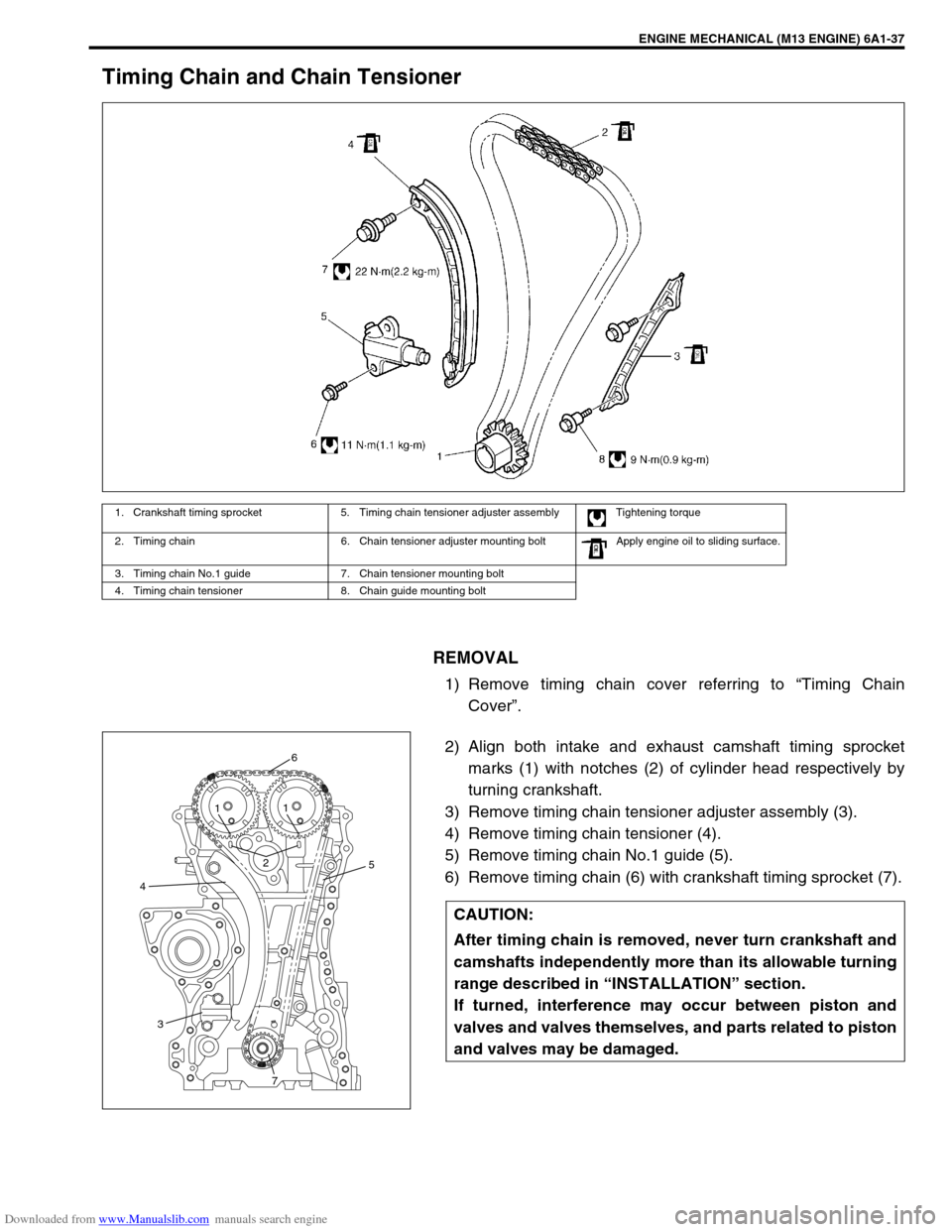
REMOVAL
1) Remove timing chain cover referring to “Timing Chain
Cover”.
2) Align both intake and exhaust camshaft timing sprocket
marks (1) with notches (2) of cylinder head respectively by
turning crankshaft.
3) Remove timing chain tensioner adjuster assembly (3).
4) Remove timing chain tensioner (4).
5) Remove timing chain No.1 guide (5).
6) Remove timing chain (6) with crankshaft timing sprocket (7).
1. Crankshaft timing sprocket 5. Timing chain tensioner adjuster assembly Tightening torque
2. Timing chain 6. Chain tensioner adjuster mounting bolt Apply engine oil to sliding surface.
3. Timing chain No.1 guide 7. Chain tensioner mounting bolt
4. Timing chain tensioner 8. Chain guide mounting bolt
CAUTION:
After timing chain is removed, never turn crankshaft and
camshafts independently more than its allowable turning
range described in “INSTALLATION” section.
If turned, interference may occur between piston and
valves and valves themselves, and parts related to piston
and valves may be damaged.
45
6
21
1
3
7
Page 550 of 687
Downloaded from www.Manualslib.com manuals search engine ENGINE MECHANICAL (M13 ENGINE) 6A1-69
6) If clearance can not be brought to within its limit even by
using a new standard size bearing, regrind crankpin to
undersize and use 0.25 mm undersize bearing.
ASSEMBLY
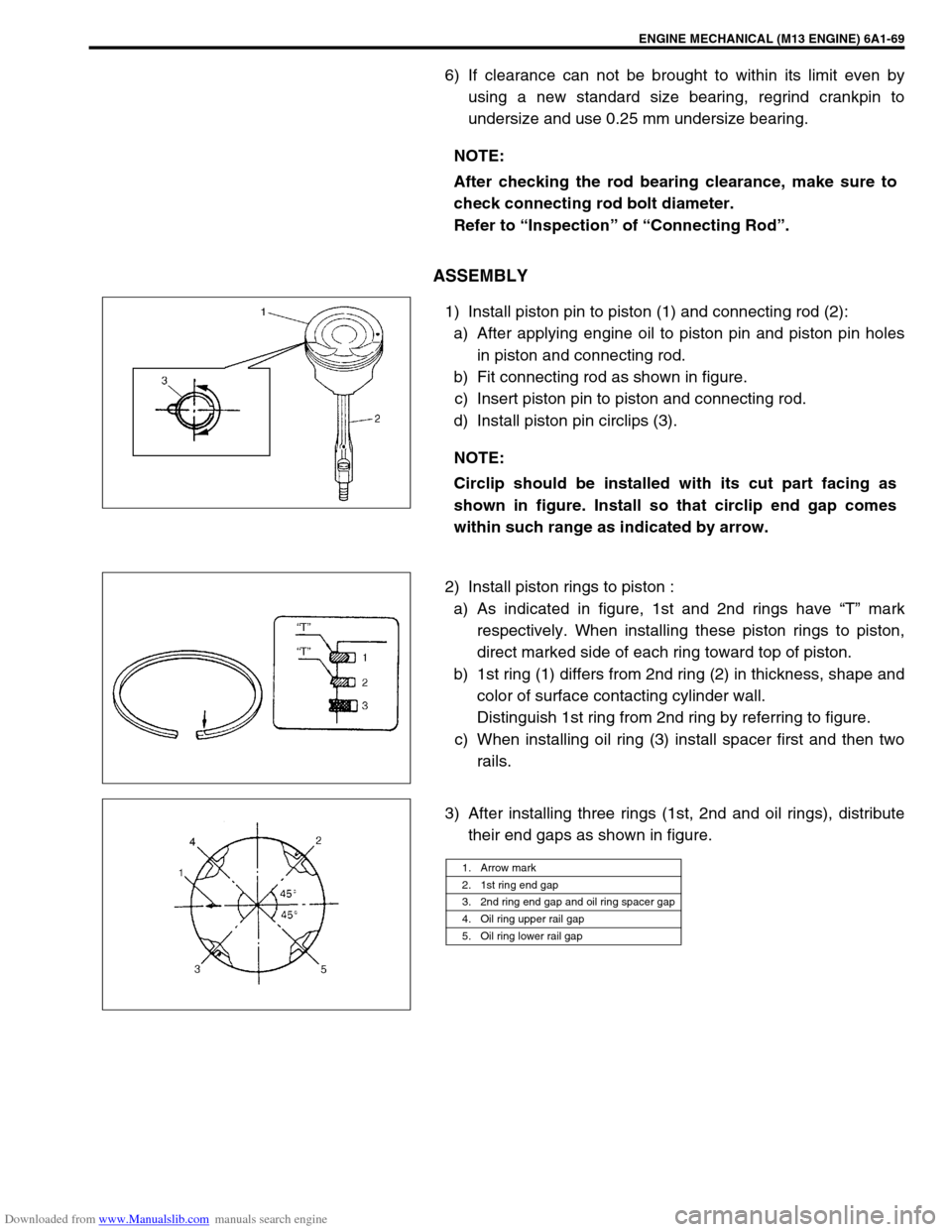
1) Install piston pin to piston (1) and connecting rod (2):
a) After applying engine oil to piston pin and piston pin holes
in piston and connecting rod.
b) Fit connecting rod as shown in figure.
c) Insert piston pin to piston and connecting rod.
d) Install piston pin circlips (3).
2) Install piston rings to piston :
a) As indicated in figure, 1st and 2nd rings have “T” mark
respectively. When installing these piston rings to piston,
direct marked side of each ring toward top of piston.
b) 1st ring (1) differs from 2nd ring (2) in thickness, shape and
color of surface contacting cylinder wall.
Distinguish 1st ring from 2nd ring by referring to figure.
c) When installing oil ring (3) install spacer first and then two
rails.
3) After installing three rings (1st, 2nd and oil rings), distribute
their end gaps as shown in figure. NOTE:
After checking the rod bearing clearance, make sure to
check connecting rod bolt diameter.
Refer to “Inspection” of “Connecting Rod”.
NOTE:
Circlip should be installed with its cut part facing as
shown in figure. Install so that circlip end gap comes
within such range as indicated by arrow.
1. Arrow mark
2. 1st ring end gap
3. 2nd ring end gap and oil ring spacer gap
4. Oil ring upper rail gap
5. Oil ring lower rail gap
Page 565 of 687

Downloaded from www.Manualslib.com manuals search engine 6A1-84 ENGINE MECHANICAL (M13 ENGINE)
5) Remove bearing caps and using scale (1) on gauging plastic
(2) envelop, measure gauging plastic width at its widest
point. If clearance exceeds its limit, replace bearing. Always
replace both upper and lower inserts as a unit.
A new standard bearing may produce proper clearance. If
not, it will be necessary to regrind crankshaft journal for use
of 0.25 mm undersize bearing.
After selecting new bearing, recheck clearance.
Main bearing clearance
Standard : 0.025 – 0.045 mm (0.0010 – 0.0018 in.)
Limit : 0.065 mm (0.0026 in.)
Selection of main bearings
STANDARD BEARING:
If bearing is in malcondition, or bearing clearance is out of specifi-
cation, select a new standard bearing according to the following
procedure and install it.
1) First check journal diameter. As shown in figure, crank web
No.2 has stamped numbers.
Three kinds of numbers (“1”, “2” and “3”) represent the fol-
lowing journal diameters.
Stamped numbers on crank web No.2 represent journal
diameters marked with an arrow in figure respectively.
For example, stamped number “1” indicates that correspond-
ing journal diameter is 44.994 – 45.000 mm (1.7714 –
1.7717 in.).
Crankshaft journal diameter NOTE:
After checking the bearing clearance, check for thread
deformation of each bearing cap No.1 bolt according to
previous mentioned Step 4) once again.
Stamped numbers Journal diameter
144.994 – 45.000 mm
(1.7714 – 1.7717 in.)
244.988 – 44.994 mm
(1.7712 – 1.7714 in.)
344.982 – 44.988 mm
(1.7709 – 1.7712 in.)
Page 566 of 687

Downloaded from www.Manualslib.com manuals search engine ENGINE MECHANICAL (M13 ENGINE) 6A1-85
2) Next, check bearing cap bore diameter without bearing. On
mating surface of cylinder block, five alphabets are stamped
as shown in figure.
Three kinds of alphabets (“A”, “B” and “C”) represent the fol-
lowing cap bore diameters.
Stamped alphabets on cylinder block represent bearing cap
bore diameter marked with an arrow in figure respectively.
For example, stamped “A” indicates that corresponding
bearing cap bore diameter is 49.000 – 49.006 mm (1.9291 –
1.9294 in.).
Crankshaft bearing cap bore
3) There are five kinds of standard bearings differing in thick-
ness. To distinguish them, they are painted in the following
colors at the center of bearings.
Each color indicates the following thickness.
Standard size of crankshaft main bearingStamped alphabetBearing cap bore diameter
(without bearing)
A49.000 – 49.006 mm
(1.9291 – 1.9294 in.)
B49.006 – 49.012 mm
(1.9294 – 1.9296 in.)
C49.012 – 49.018 mm
(1.9296 – 1.9298 in.)
Color painted Bearing thickness
Pink1.990 – 1.994 mm
(0.0783 – 0.0785 in.)
Purple1.993 – 1.997 mm
(0.0785 – 0.0786 in.)
Brown1.996 – 2.000 mm
(0.0786 – 0.0787 in.)
Green1.999 – 2.003 mm
(0.0787 – 0.0789 in.)
Black2.002 – 2.006 mm
(0.0788 – 0.0790 in.)
1. Paint
Page 610 of 687
Downloaded from www.Manualslib.com manuals search engine ENGINE AND EMISSION CONTROL SYSTEM 6E-5
Air Intake System
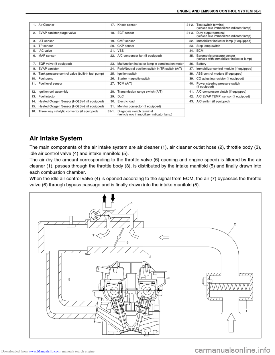
The main components of the air intake system are air cleaner (1), air cleaner outlet hose (2), throttle body (3),
idle air control valve (4) and intake manifold (5).
The air (by the amount corresponding to the throttle valve (6) opening and engine speed) is filtered by the air
cleaner (1), passes through the throttle body (3), is distributed by the intake manifold (5) and finally drawn into
each combustion chamber.
When the idle air control valve (4) is opened according to the signal from ECM, the air (7) bypasses the throttle
valve (6) through bypass passage and is finally drawn into the intake manifold (5).
1. Air Cleaner 17. Knock sensor 31-2. Test switch terminal
(vehicle w/o immobilizer indicator lamp)
2. EVAP canister purge valve 18. ECT sensor 31-3. Duty output terminal
(vehicle w/o immobilizer indicator lamp)
3. IAT sensor 19. CMP sensor 32. Immobilizer indicator lamp (if equipped)
4. TP sensor 20. CKP sensor 33. Stop lamp switch
5. IAC valve 21. VSS 34. ECM
6. MAP sensor 22. A/C condenser fan (if equipped) 35. Barometric pressure sensor
(vehicle with immobilizer indicator lamp)
7. EGR valve (if equipped) 23. Malfunction indicator lamp in combination meter 36. Battery
8. EVAP canister 24. Park/Neutral position switch in TR switch (A/T) 37. Immobilizer control module (if equipped)
9. Tank pressure control valve (built-in fuel pump) 25. Ignition switch 38. ABS control module (if equipped)
10. Fuel pump 26. Starter magnetic switch 39. CO adjusting resistor (if equipped)
11. Fuel level sensor 27. TCM (A/T) 40. Power steering pressure switch
(if equipped)
12. Ignition coil assembly 28. Transmission range switch (A/T) 41. A/C compressor clutch (if equipped)
13. Fuel injector 29. DLC 42. A/C EVAP TEMP. sensor (if equipped)
14. Heated Oxygen Sensor (HO2S)-1 (if equipped) 30. Electric load 43. A/C switch (if equipped)
15. Heated Oxygen Sensor (HO2S)-2 (if equipped) 31. Monitor connector (if equipped)
16. Three way catalytic convertor (if equipped) 31-1. Diagnosis switch terminal
(vehicle w/o immobilizer indicator lamp)
Page 642 of 687
Downloaded from www.Manualslib.com manuals search engine ENGINE AND EMISSION CONTROL SYSTEM 6E-37
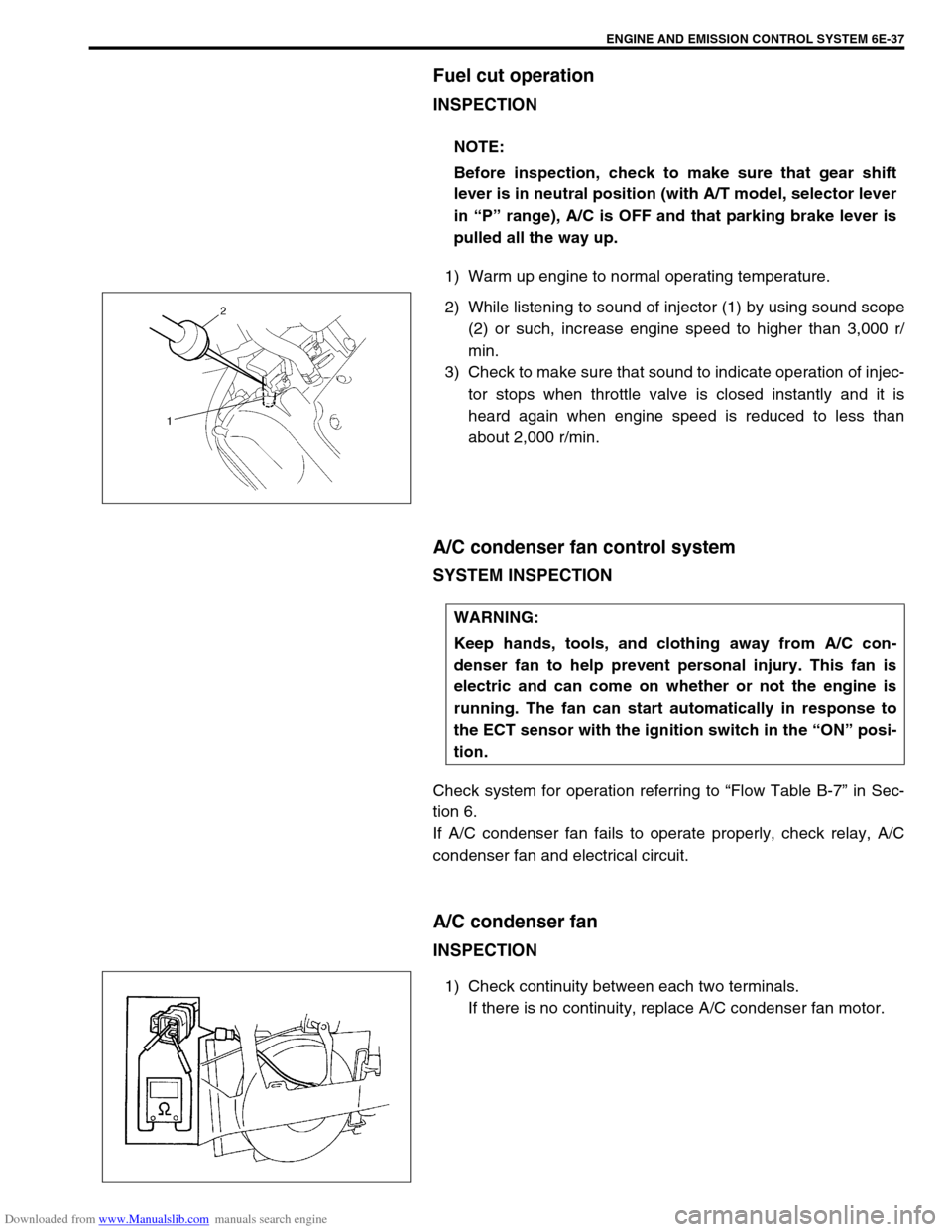
Fuel cut operation
INSPECTION
1) Warm up engine to normal operating temperature.
2) While listening to sound of injector (1) by using sound scope
(2) or such, increase engine speed to higher than 3,000 r/
min.
3) Check to make sure that sound to indicate operation of injec-
tor stops when throttle valve is closed instantly and it is
heard again when engine speed is reduced to less than
about 2,000 r/min.
A/C condenser fan control system
SYSTEM INSPECTION
Check system for operation referring to “Flow Table B-7” in Sec-
tion 6.
If A/C condenser fan fails to operate properly, check relay, A/C
condenser fan and electrical circuit.
A/C condenser fan
INSPECTION
1) Check continuity between each two terminals.
If there is no continuity, replace A/C condenser fan motor. NOTE:
Before inspection, check to make sure that gear shift
lever is in neutral position (with A/T model, selector lever
in “P” range), A/C is OFF and that parking brake lever is
pulled all the way up.
WARNING:
Keep hands, tools, and clothing away from A/C con-
denser fan to help prevent personal injury. This fan is
electric and can come on whether or not the engine is
running. The fan can start automatically in response to
the ECT sensor with the ignition switch in the “ON” posi-
tion.