service SUZUKI JIMNY 2005 3.G Service Owner's Manual
[x] Cancel search | Manufacturer: SUZUKI, Model Year: 2005, Model line: JIMNY, Model: SUZUKI JIMNY 2005 3.GPages: 687, PDF Size: 13.38 MB
Page 54 of 687
Downloaded from www.Manualslib.com manuals search engine HEATER AND VENTILATION 1A-1
6F1
6G
1A
6K
6K
7A
7A1
7B1
7C1
7D
7E
7F
8A
8B
8C
8D
8E
9
10
10A
10B
SECTION 1A
HEATER AND VENTILATION
CONTENTS
General Description ....................................... 1A-2
Diagnosis ........................................................ 1A-3
Diagnosis Table ........................................... 1A-3
Wiring Circuit ................................................ 1A-3
On Vehicle Service ......................................... 1A-4Heater Blower Motor .................................... 1A-4
Heater Blower Resistor ................................ 1A-5
Heater Control Lever Assembly ................... 1A-5
Heater Blower Fan Switch ........................... 1A-7
Heater Unit/Boost Ventilation ....................... 1A-7
WARNING:
For vehicles equipped with Supplement Restraint (Air Bag) System
Service on and around the air bag system components or wiring must be performed only by an
authorized SUZUKI dealer. Refer to “Air Bag System Components and Wiring Location View” under
“General Description” in Section 10B in order to confirm whether you are performing service on or
near the air bag system components or wiring. Please observe all WARNINGS and “Service Precau-
tions” under “On-Vehicle Service” in Section 10B before performing service on or around the air
bag system components or wiring. Failure to follow WARNINGS could result in unintentional activa-
tion of the system or could render the system inoperative. Either or these two conditions may result
in severe injury.
Technical service work must be started at least 90 seconds after the ignition switch is turned to the
“LOCK” position and the negative cable is disconnected from the battery. Otherwise, the system
may be activated by reserve energy in the Sensing and Diagnostic Module (SDM).
NOTE:
The link mechanism of the heater varies depending on the specifications.
Page 57 of 687
Downloaded from www.Manualslib.com manuals search engine 1A-4 HEATER AND VENTILATION
On Vehicle Service
Heater Blower Motor
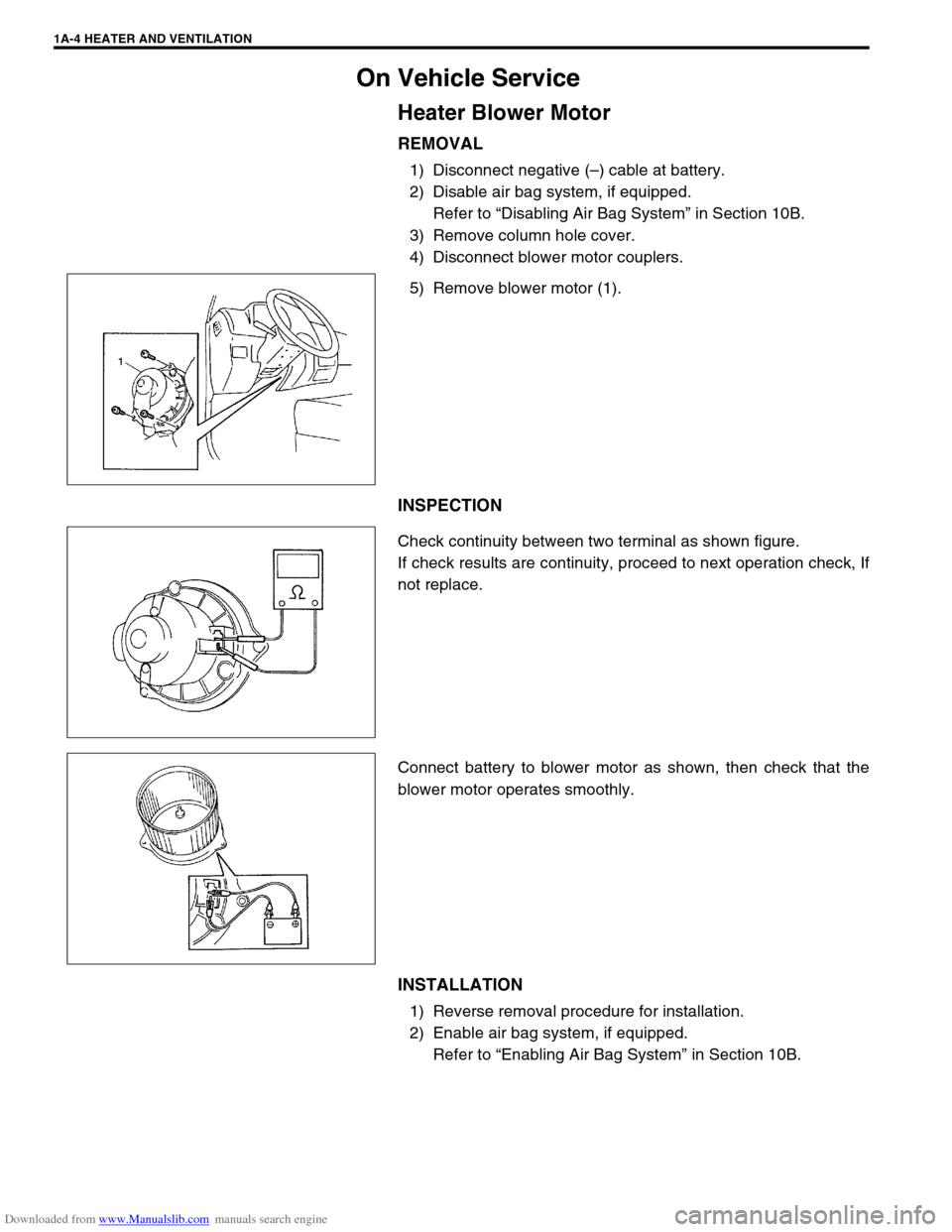
REMOVAL
1) Disconnect negative (–) cable at battery.
2) Disable air bag system, if equipped.
Refer to “Disabling Air Bag System” in Section 10B.
3) Remove column hole cover.
4) Disconnect blower motor couplers.
5) Remove blower motor (1).
INSPECTION
Check continuity between two terminal as shown figure.
If check results are continuity, proceed to next operation check, If
not replace.
Connect battery to blower motor as shown, then check that the
blower motor operates smoothly.
INSTALLATION
1) Reverse removal procedure for installation.
2) Enable air bag system, if equipped.
Refer to “Enabling Air Bag System” in Section 10B.
Page 62 of 687
Downloaded from www.Manualslib.com manuals search engine AIR CONDITIONING (OPTIONAL) 1B-1
6F1
6F2
1B
7A
7A1
7B1
7C1
7D
7E
7F
8A
8B
8C
8D
8E
9
10
10A
10B
SECTION 1B
AIR CONDITIONING (OPTIONAL)
CONTENTS
General Description ....................................... 1B-3
Major Components and Location ................. 1B-3
Refrigerant Circulation ................................. 1B-4
Refrigerant Type .......................................... 1B-4
Diagnosis ........................................................ 1B-5
General Diagnosis Table .............................. 1B-5
Abnormal Noise Diagnosis ........................... 1B-7
Abnormal noise from compressor ............ 1B-7
Abnormal noise from magnetic clutch ...... 1B-7
Abnormal noise from tubing ..................... 1B-7
Abnormal noise from condenser .............. 1B-7
Abnormal noise from crankshaft pulley .... 1B-8
Abnormal noise from tension pulley ......... 1B-8
Abnormal noise from A/C evaporator ....... 1B-8
Abnormal noise from blower fan motor .... 1B-8
Quick Checking of Refrigerant Charge......... 1B-9Performance Diagnosis.............................. 1B-10
Performance diagnosis table.................. 1B-12
Detail diagnosis table (Ambient
temperature at 30°C (86°F)) .................. 1B-13
Compressor Drive Belt ............................... 1B-15
Electronical Diagnosis ................................ 1B-16
Wiring Diagram .......................................... 1B-16
A/C System Inspection of ECM and ITS
Circuits ....................................................... 1B-17
Refrigerant Recovery, Evacuating and
Charging ....................................................... 1B-21
Operation Procedure for Refrigerant
Charging .................................................... 1B-21
Recovery .................................................... 1B-22
Replenishing Compressor Oil .................... 1B-22 WARNING:
For vehicles equipped with Supplemental Restraint (Air Bag) System:
Service on and around the air bag system components or wiring must be performed only by an
authorized SUZUKI dealer. Refer to “Air Bag System Components and Wiring Location View” under
“General Description” in air bag system section in order to confirm whether you are performing ser-
vice on or near the air bag system components or wiring. Please observe all WARNINGS and “Ser-
vice Precautions” under “On-Vehicle Service” in air bag system section before performing service
on or around the air bag system components or wiring. Failure to follow WARNINGS could result in
unintentional activation of the system or could render the system inoperative. Either of these two
conditions may result in severe injury.
Technical service work must be started at least 90 seconds after the ignition switch is turned to the
“LOCK” position and the negative cable is disconnected from the battery. Otherwise, the system
may be activated by reserve energy in the Sensing and Diagnostic Module (SDM).
CAUTION:
The air conditioning system of this vehicle uses refrigerant HFC-134a (R-134a).
None of refrigerant, compressor oil and component parts is interchangeable between two types of
A/C: one using refrigerant HFC-134a (R-134a) and the other using refrigerant CFC-12 (R-12).
Be sure to check which refrigerant is used before any service work including inspection and mainte-
nance. For identification between these two types, refer to “Refrigerant Type” in this section.
When replenishing or changing refrigerant and compressor oil and when replacing parts, make sure
that the material or the part to be used is appropriate to the A/C installed in the vehicle being serviced.
Use of incorrect one will result in leakage of refrigerant, damage in parts or other faulty condition.
NOTE:
For basic servicing method of the air conditioning system that is not described in this section, refer to
AIR CONDITIONING BASIC MANUAL (Part number: 99520-02130).
Page 63 of 687

Downloaded from www.Manualslib.com manuals search engine 1B-2 AIR CONDITIONING (OPTIONAL)
Evacuating ................................................. 1B-23
Evacuating procedure ............................ 1B-23
Charging .................................................... 1B-25
Charging procedure ............................... 1B-25
Removing Manifold Gauge Set .................. 1B-28
Leak Test ................................................... 1B-28
On-Vehicle Service ...................................... 1B-29
Service Precaution ..................................... 1B-29
Refrigerant line ....................................... 1B-29
Handling refrigerant HFC-134a
(R-134a) ................................................. 1B-30
Condenser Assembly ................................. 1B-31
Receiver / Dryer ......................................... 1B-32
Condenser Cooling Fan Assembly ............ 1B-33Cooling Unit (Evaporator) .......................... 1B-34
A/C Evaporator Thermistor (A/C Evaporator
Temperature Sensor)................................. 1B-37
Expansion Valve ........................................ 1B-37
Dual Pressure Switch ................................ 1B-38
A/C Switch ................................................. 1B-39
Condenser Cooling Fan Motor Relay ........ 1B-39
Compressor ............................................... 1B-39
Magnet Clutch............................................ 1B-41
Lip Type Seal ............................................. 1B-45
Tightening Torque Specification................ 1B-46
Required Service Materials ......................... 1B-47
Special Tools ............................................... 1B-47
Page 64 of 687
Downloaded from www.Manualslib.com manuals search engine AIR CONDITIONING (OPTIONAL) 1B-3
General Description
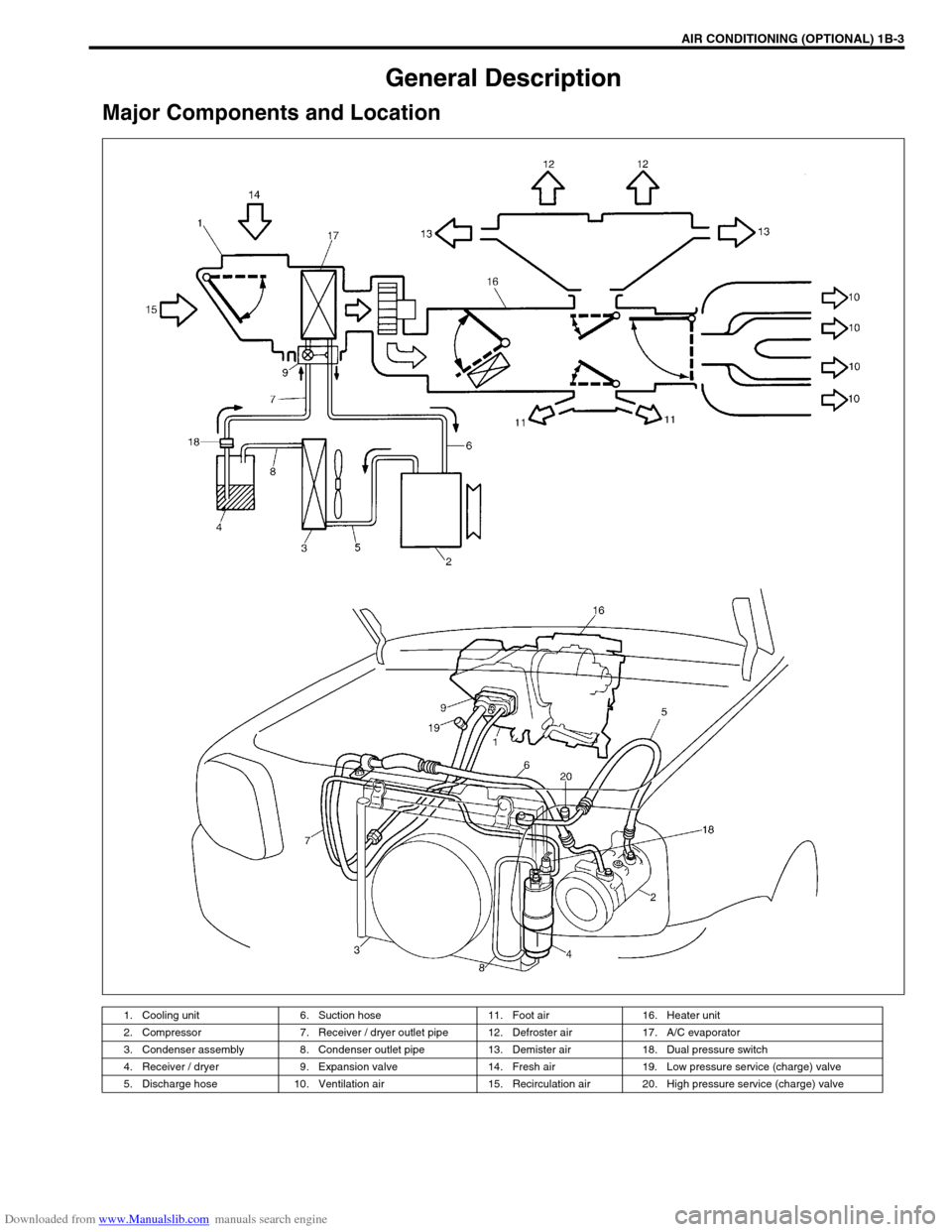
Major Components and Location
1. Cooling unit 6. Suction hose 11. Foot air 16. Heater unit
2. Compressor 7. Receiver / dryer outlet pipe 12. Defroster air 17. A/C evaporator
3. Condenser assembly 8. Condenser outlet pipe 13. Demister air 18. Dual pressure switch
4. Receiver / dryer 9. Expansion valve 14. Fresh air 19. Low pressure service (charge) valve
5. Discharge hose 10. Ventilation air 15. Recirculation air 20. High pressure service (charge) valve
Page 65 of 687
Downloaded from www.Manualslib.com manuals search engine 1B-4 AIR CONDITIONING (OPTIONAL)
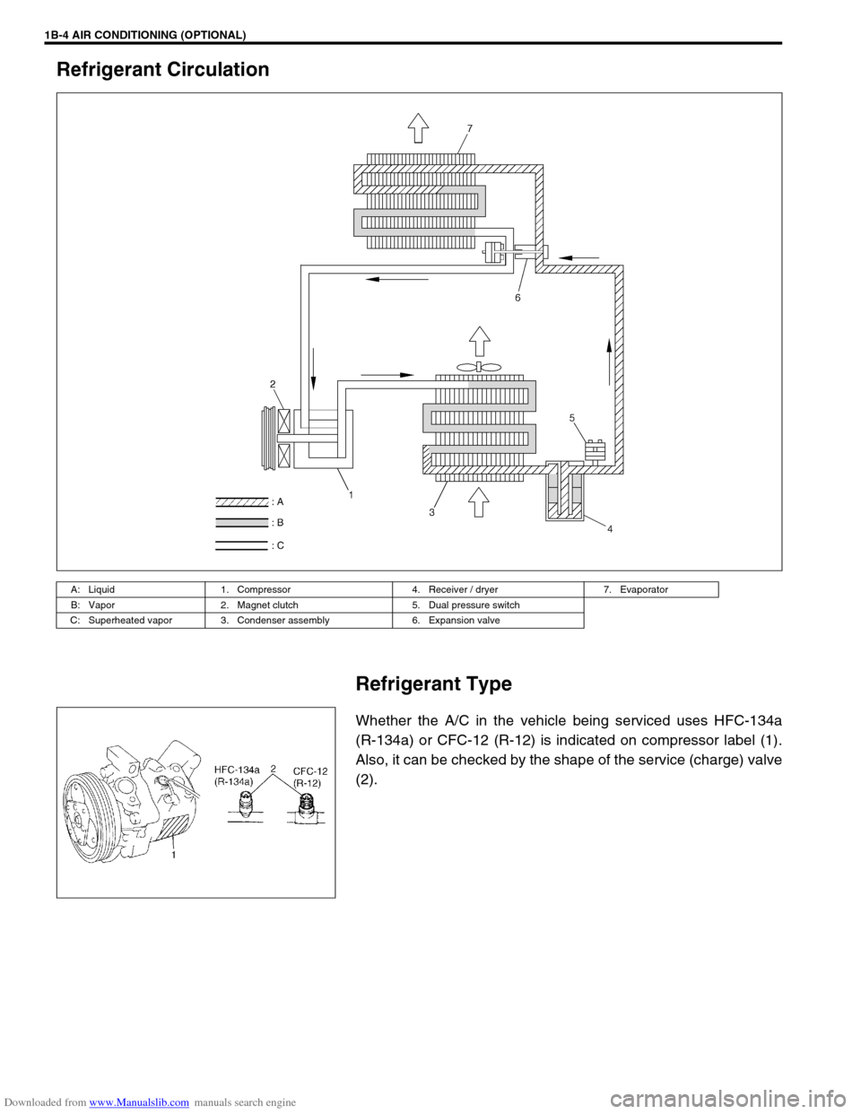
Refrigerant Circulation
Refrigerant Type
Whether the A/C in the vehicle being serviced uses HFC-134a
(R-134a) or CFC-12 (R-12) is indicated on compressor label (1).
Also, it can be checked by the shape of the service (charge) valve
(2).
A: Liquid 1. Compressor 4. Receiver / dryer 7. Evaporator
B: Vapor 2. Magnet clutch 5. Dual pressure switch
C: Superheated vapor 3. Condenser assembly 6. Expansion valve
Page 71 of 687
Downloaded from www.Manualslib.com manuals search engine 1B-10 AIR CONDITIONING (OPTIONAL)
Performance Diagnosis
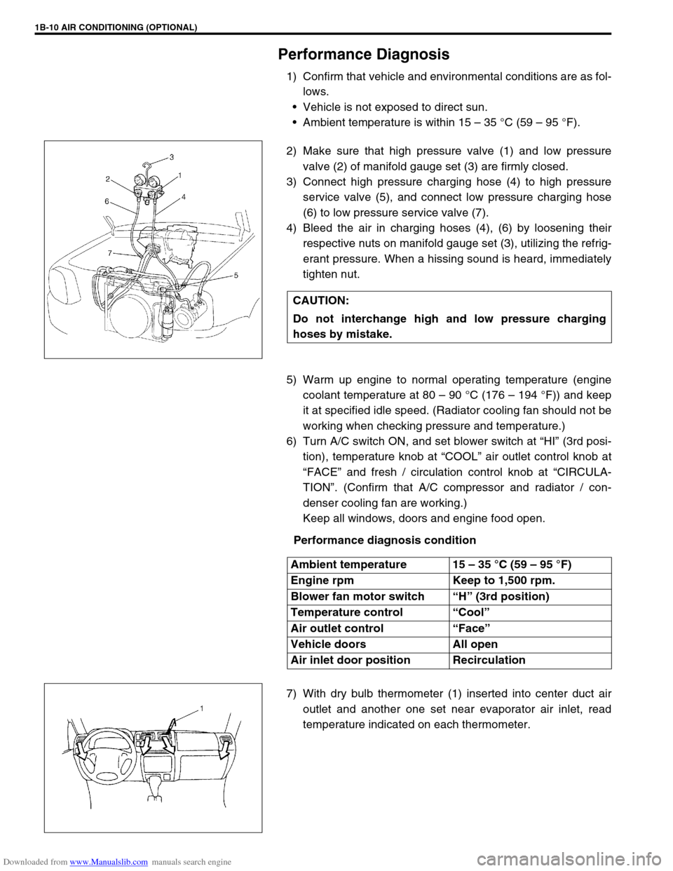
1) Confirm that vehicle and environmental conditions are as fol-
lows.
Vehicle is not exposed to direct sun.
Ambient temperature is within 15 – 35 °C (59 – 95 °F).
2) Make sure that high pressure valve (1) and low pressure
valve (2) of manifold gauge set (3) are firmly closed.
3) Connect high pressure charging hose (4) to high pressure
service valve (5), and connect low pressure charging hose
(6) to low pressure service valve (7).
4) Bleed the air in charging hoses (4), (6) by loosening their
respective nuts on manifold gauge set (3), utilizing the refrig-
erant pressure. When a hissing sound is heard, immediately
tighten nut.
5) Warm up engine to normal operating temperature (engine
coolant temperature at 80 – 90 °C (176 – 194 °F)) and keep
it at specified idle speed. (Radiator cooling fan should not be
working when checking pressure and temperature.)
6) Turn A/C switch ON, and set blower switch at “HI” (3rd posi-
tion), temperature knob at “COOL” air outlet control knob at
“FACE” and fresh / circulation control knob at “CIRCULA-
TION”. (Confirm that A/C compressor and radiator / con-
denser cooling fan are working.)
Keep all windows, doors and engine food open.
Performance diagnosis condition
7) With dry bulb thermometer (1) inserted into center duct air
outlet and another one set near evaporator air inlet, read
temperature indicated on each thermometer. CAUTION:
Do not interchange high and low pressure charging
hoses by mistake.
Ambient temperature 15 – 35 °C (59 – 95 °F)
Engine rpm Keep to 1,500 rpm.
Blower fan motor switch “H” (3rd position)
Temperature control “Cool”
Air outlet control “Face”
Vehicle doors All open
Air inlet door position Recirculation
Page 86 of 687

Downloaded from www.Manualslib.com manuals search engine AIR CONDITIONING (OPTIONAL) 1B-25
Charging
Charging procedure
The initial charging of the A/C system is performed from the high
pressure side with the engine stopped.
And next, this method must be followed by charging from the low
pressure side with the engine running.
1) Check to make sure that hoses are routed properly after
evacuating the system. CAUTION:
Always charge through low pressure side of A/C sys-
tem at after the initial charging is performed from the
high pressure side with the engine stopped.
Never charge to high pressure side of A/C system with
engine running.
Do not charge while compressor is hot.
When installing tap valve to refrigerant container to
make a hole there through, carefully follow directions
given by manufacturer.
A pressure gauge should always be used before and
during charging.
The refrigerant container should be emptied of refrig-
erant when discarding it.
The refrigerant container should not be heated up to
40 °C (104 °F) or over.
Refrigerant container should not be reversed in direc-
tion during charging. Reversing in direction causes liq-
uid refrigerant to enter compressor, causing troubles,
such as compression of liquid refrigerant and the like.
NOTE:
The air conditioning system contains HFC-134a (R-134a).
Described here is a method to charge the air conditioning
system with refrigerant from the refrigerant service con-
tainer.
When charging refrigerant recovered by using the refrig-
erant and recycling equipment (when recycling refriger-
ant), follow the procedure described in the equipment
manufacturer’s instruction manual.
Page 89 of 687
Downloaded from www.Manualslib.com manuals search engine 1B-28 AIR CONDITIONING (OPTIONAL)
Removing Manifold Gauge Set
When A/C system has been charged with a specified amount of
refrigerant, remove manifold gauge set as follows:
1) Close low pressure side valve of manifold gauge set. (The
high pressure side valve is closed continuously during the
process of charging.)
2) Close refrigerant container valve.
3) Stop engine.
4) Using shop rag, remove charging hoses from service valves.
This operation must be performed rapidly.
5) Put caps on service valves.
Leak Test
Whenever a refrigerant leak is suspected in the system or any
service operation has been performed which may result in dis-
turbing lines or connections, it is advisable to test for leaks.
Common sense should be used in performing any refrigerant leak
test, since the need and extent of any such test will, in general,
depend upon the nature of a complaint and the type of a service
performed on the system.
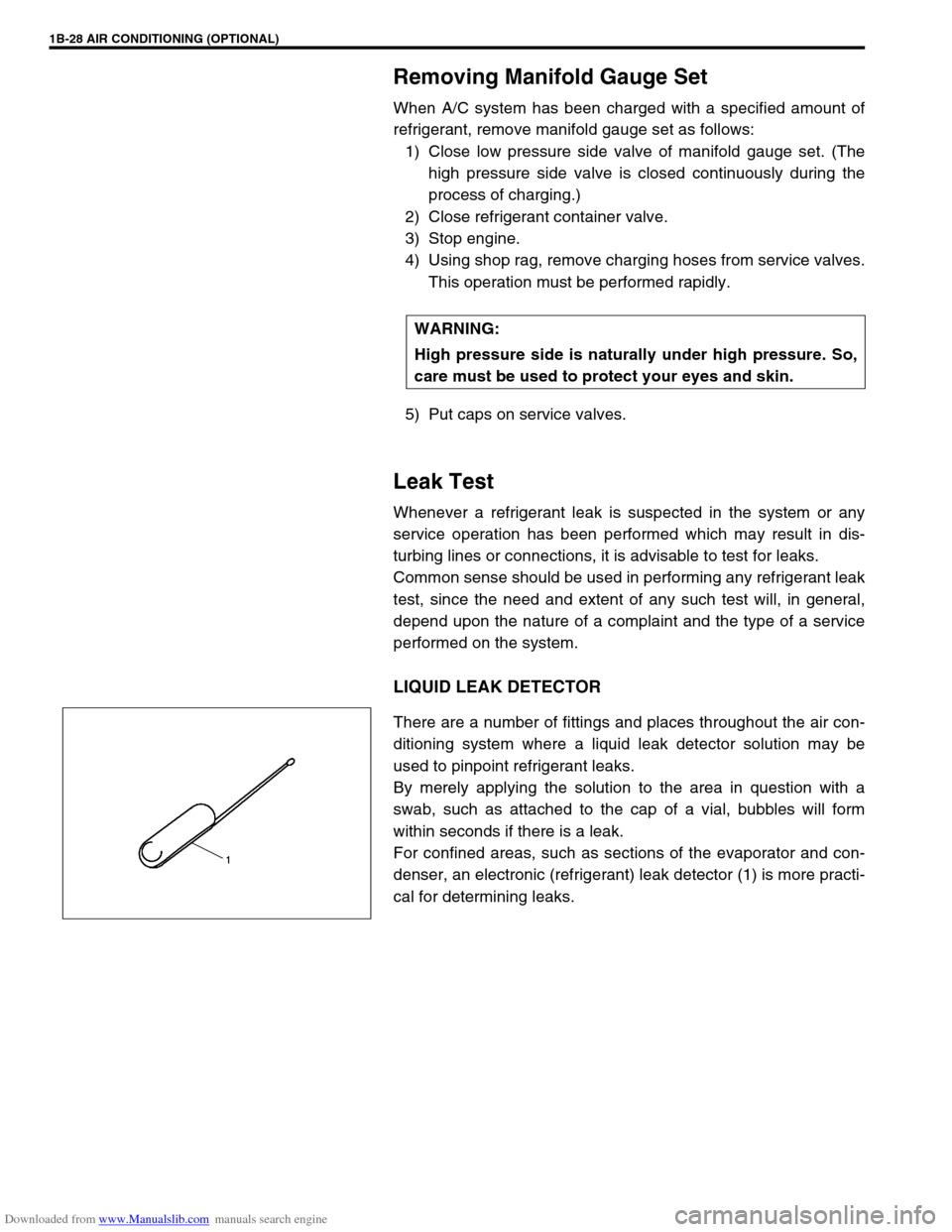
LIQUID LEAK DETECTOR
There are a number of fittings and places throughout the air con-
ditioning system where a liquid leak detector solution may be
used to pinpoint refrigerant leaks.
By merely applying the solution to the area in question with a
swab, such as attached to the cap of a vial, bubbles will form
within seconds if there is a leak.
For confined areas, such as sections of the evaporator and con-
denser, an electronic (refrigerant) leak detector (1) is more practi-
cal for determining leaks.WARNING:
High pressure side is naturally under high pressure. So,
care must be used to protect your eyes and skin.
Page 90 of 687
Downloaded from www.Manualslib.com manuals search engine AIR CONDITIONING (OPTIONAL) 1B-29
On-Vehicle Service
Service Precaution
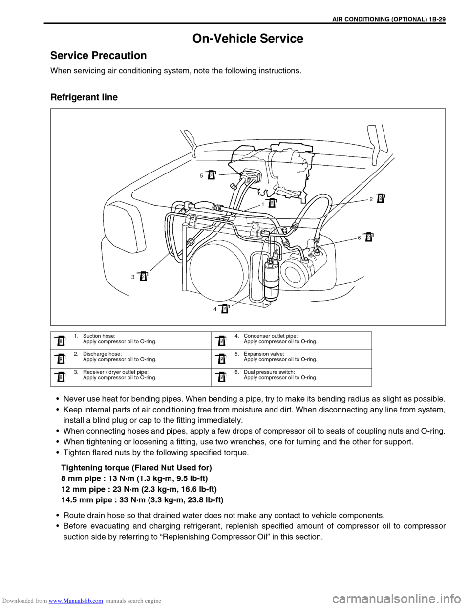
When servicing air conditioning system, note the following instructions.
Refrigerant line
Never use heat for bending pipes. When bending a pipe, try to make its bending radius as slight as possible.
Keep internal parts of air conditioning free from moisture and dirt. When disconnecting any line from system,
install a blind plug or cap to the fitting immediately.
When connecting hoses and pipes, apply a few drops of compressor oil to seats of coupling nuts and O-ring.
When tightening or loosening a fitting, use two wrenches, one for turning and the other for support.
Tighten flared nuts by the following specified torque.
Tightening torque (Flared Nut Used for)
8 mm pipe : 13 N·m (1.3 kg-m, 9.5 lb-ft)
12 mm pipe : 23 N·m (2.3 kg-m, 16.6 lb-ft)
14.5 mm pipe : 33 N·m (3.3 kg-m, 23.8 lb-ft)
Route drain hose so that drained water does not make any contact to vehicle components.
Before evacuating and charging refrigerant, replenish specified amount of compressor oil to compressor
suction side by referring to “Replenishing Compressor Oil” in this section.
1. Suction hose:
Apply compressor oil to O-ring.4. Condenser outlet pipe:
Apply compressor oil to O-ring.
2. Discharge hose:
Apply compressor oil to O-ring.5. Expansion valve:
Apply compressor oil to O-ring.
3. Receiver / dryer outlet pipe:
Apply compressor oil to O-ring.6. Dual pressure switch:
Apply compressor oil to O-ring.