service SUZUKI JIMNY 2005 3.G Service Repair Manual
[x] Cancel search | Manufacturer: SUZUKI, Model Year: 2005, Model line: JIMNY, Model: SUZUKI JIMNY 2005 3.GPages: 687, PDF Size: 13.38 MB
Page 254 of 687
Downloaded from www.Manualslib.com manuals search engine PROPELLER SHAFTS 4B-1
6F1
6F2
6G
6H
6K
7A
7A1
7B1
7C1
7D
4B
8D
8E
9
8E
9
10
10A
10B
SECTION 4B
PROPELLER SHAFTS
CONTENTS
General Description ....................................... 4B-2
Components ................................................. 4B-2
Diagnosis ........................................................ 4B-2
Diagnosis Table ........................................... 4B-2
Propeller Shaft Joint Check .......................... 4B-2
On-Vehicle Service......................................... 4B-3Propeller Shafts ........................................... 4B-3
Universal Joint ............................................. 4B-5
Tightening Torque Specification .................. 4B-7
Required Service Material ............................. 4B-7
Special Tool .................................................... 4B-8
NOTE:
All propeller shaft fasteners are an important attaching part in that it could affect the performance
of vital parts and systems, and/or could result in major repair expense. They must be replaced with
one of the same part number or with an equivalent part if replacement becomes necessary. Do not
use a replacement part of lesser quality or substitute design. Torque values must be used as speci-
fied during reassembly to assure proper retention of this part.
Never attempt to heat, quench or straighten any propeller shaft part. Replace it with a new part, or
damage to the part may result.
Page 256 of 687
Downloaded from www.Manualslib.com manuals search engine PROPELLER SHAFTS 4B-3
On-Vehicle Service
Propeller Shafts
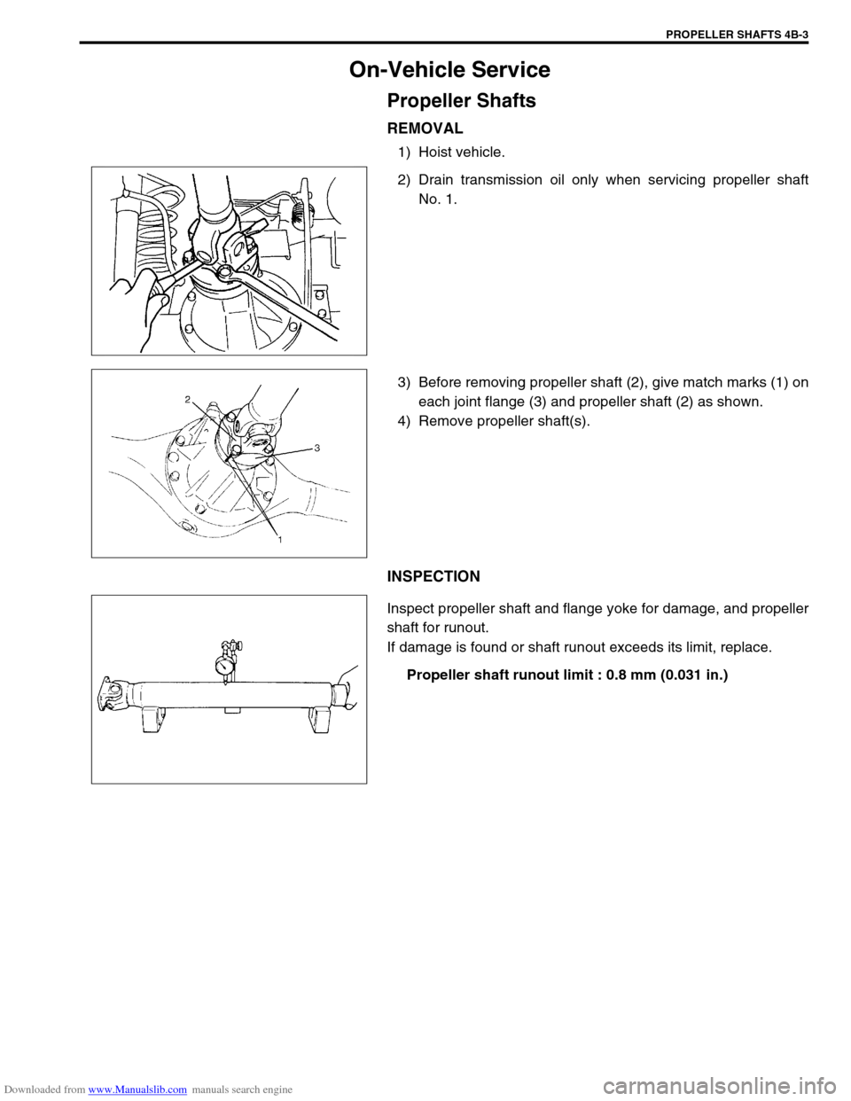
REMOVAL
1) Hoist vehicle.
2) Drain transmission oil only when servicing propeller shaft
No. 1.
3) Before removing propeller shaft (2), give match marks (1) on
each joint flange (3) and propeller shaft (2) as shown.
4) Remove propeller shaft(s).
INSPECTION
Inspect propeller shaft and flange yoke for damage, and propeller
shaft for runout.
If damage is found or shaft runout exceeds its limit, replace.
Propeller shaft runout limit : 0.8 mm (0.031 in.)
Page 260 of 687
Downloaded from www.Manualslib.com manuals search engine PROPELLER SHAFTS 4B-7
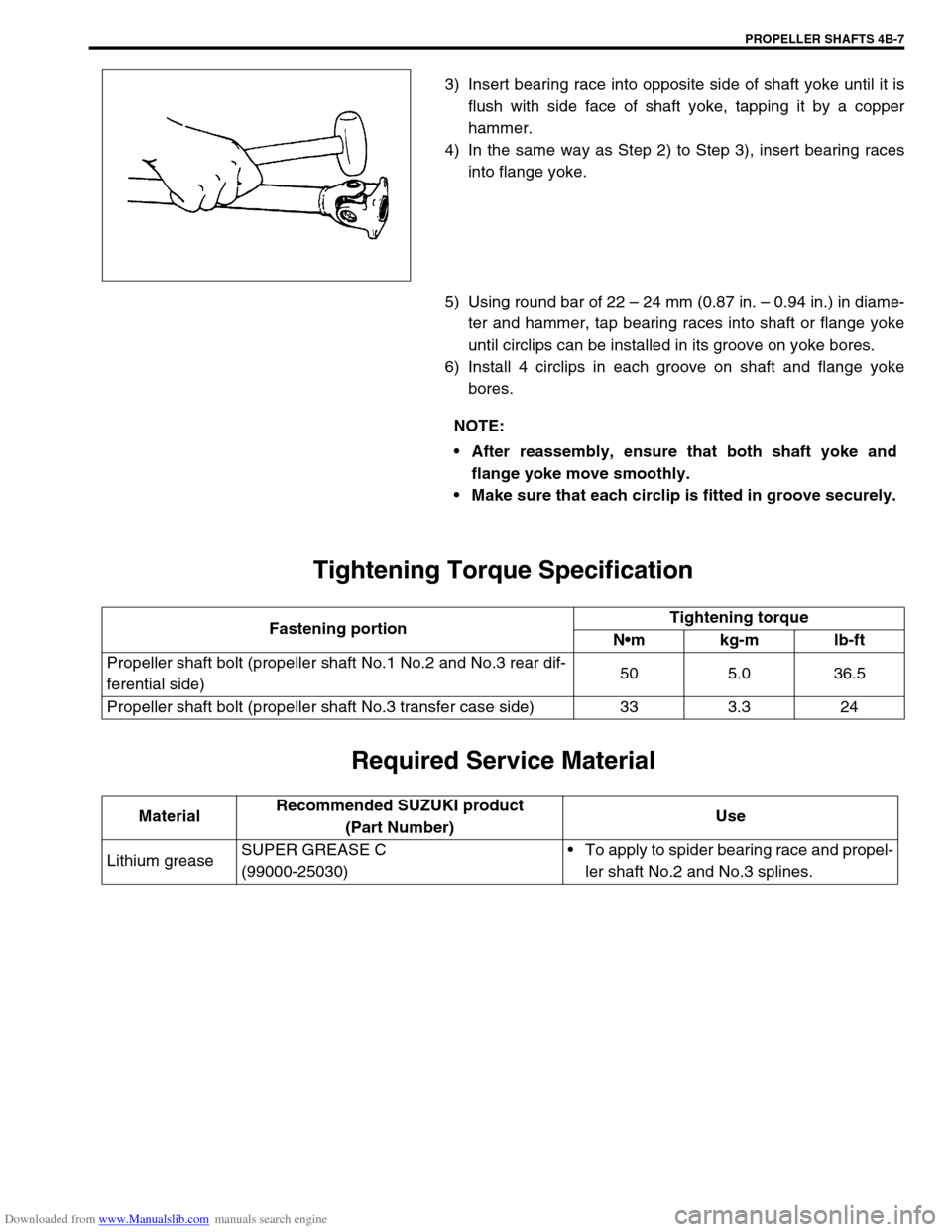
3) Insert bearing race into opposite side of shaft yoke until it is
flush with side face of shaft yoke, tapping it by a copper
hammer.
4) In the same way as Step 2) to Step 3), insert bearing races
into flange yoke.
5) Using round bar of 22 – 24 mm (0.87 in. – 0.94 in.) in diame-
ter and hammer, tap bearing races into shaft or flange yoke
until circlips can be installed in its groove on yoke bores.
6) Install 4 circlips in each groove on shaft and flange yoke
bores.
Tightening Torque Specification
Required Service Material
NOTE:
After reassembly, ensure that both shaft yoke and
flange yoke move smoothly.
Make sure that each circlip is fitted in groove securely.
Fastening portionTightening torque
Nm kg-m lb-ft
Propeller shaft bolt (propeller shaft No.1 No.2 and No.3 rear dif-
ferential side)50 5.0 36.5
Propeller shaft bolt (propeller shaft No.3 transfer case side) 33 3.3 24
MaterialRecommended SUZUKI product
(Part Number)Use
Lithium greaseSUPER GREASE C
(99000-25030)To apply to spider bearing race and propel-
ler shaft No.2 and No.3 splines.
Page 262 of 687
Downloaded from www.Manualslib.com manuals search engine BRAKES 5-1
6F1
6F2
6G
6H
6K
7A
7A1
7B1
7C1
7D
7E
5
9
10
10A
10B
9
10
10A
10B
SECTION 5
BRAKES
CONTENTS
General Description ......................................... 5-3
Diagnosis .......................................................... 5-4
Road Testing Brakes ...................................... 5-4
Brake Fluid Leaks .......................................... 5-4
Substandard or Contaminated Brake Fluid .... 5-4
Diagnosis Table ............................................. 5-5
Brake Pedal Free Height Adjustment ............. 5-8
Brake Pedal Play Check ................................ 5-8
Stop Light Switch Adjustment ........................ 5-8
Excessive Pedal Travel Check ....................... 5-9
Front Brake Disc Check ................................. 5-9
Front Brake Pad Check .................................. 5-9
Rear Brake Shoe Check .............................. 5-10
Master Cylinder and Brake Fluid Level
Check ........................................................... 5-10
Rear Drum Brake Shoe Adjustment ............. 5-11
Parking Brake Inspection and Adjustment ... 5-11
Booster Operation Check ............................. 5-12Fluid Pressure Test
(If Equipped with LSPV) ............................... 5-15
On-Vehicle Service ........................................ 5-17
Air Bleeding of Brake System ...................... 5-17
Brake Hose and Pipe Inspection.................. 5-18
Front Disc Brake .......................................... 5-19
Brake pad ................................................. 5-20
Caliper assembly...................................... 5-22
Brake Disc.................................................... 5-26
Rear Brake ................................................... 5-29
Brake drum............................................... 5-29
Brake shoe ............................................... 5-32
Wheel Cylinder............................................. 5-33
Brake back plate ...................................... 5-34
Master Cylinder .............................................. 5-36
Master Cylinder Reservoir ........................... 5-36
Master Cylinder Assembly ........................... 5-37 WARNING:
For lifting point of vehicle, refer to Section 0A.
WARNING:
For vehicles equipped with Supplement Restraint (Air Bag) System:
Service on and around the air bag system components or wiring must be performed only by an
authorized SUZUKI dealer. Refer to “Air Bag System Components and Wiring Location View” under
“General Description” in air bag system section in order to confirm whether you are performing ser-
vice on or near the air bag system components or wiring. Please observe all WARNINGS and “Ser-
vice Precautions” under “On-Vehicle Service” in air bag system section before performing service
on or around the air bag system components or wiring. Failure to follow WARNINGS could result in
unintentional activation of the system or could render the system inoperative. Either of these two
conditions may result in severe injury.
Technical service work must be started at least 90 seconds after the ignition switch is turned to the
“LOCK” position and the negative cable is disconnected from the battery. Otherwise, the system
may be activated by reserve energy in the Sensing and Diagnostic Module (SDM).
NOTE:
When inspecting and servicing vehicle equipped with ABS, be sure to refer to section 5E first.
All brake fasteners are important attaching parts in that they could affect the performance of vital
parts and systems, and/or could result in major repair expense. They must be replaced with one of
same part number or with an equivalent part if replacement becomes necessary. Do not use a
replacement part of lesser quality or substitute design. Torque values must be used as specified
during reassembly to assure proper retention of all parts. There is to be no welding as it may result
in extensive damage and weakening of the metal.
Page 263 of 687

Downloaded from www.Manualslib.com manuals search engine 5-2 BRAKES
Master Cylinder ............................................ 5-38
Fill Reservoir ................................................ 5-40
LSPV (Load Sensing Proportioning Valve)
Assembly (If Equipped) ................................. 5-42
LSPV Assembly ........................................... 5-43
P (Proportioning) Valve ................................. 5-44
Brake Booster ................................................ 5-45
Inspection and adjustment ....................... 5-46
Brake Hose/Pipe .......................................... 5-48Front brake hose/pipe ............................... 5-48
Rear Brake Hose/Pipe .................................. 5-51
Parking Brake Lever/Cable ........................... 5-52
Parking brake lever ................................... 5-52
Parking Brake Cable ..................................... 5-53
Tightening Torque Specifications ................. 5-54
Required Service Material.............................. 5-54
Special Tool .................................................... 5-55
Page 272 of 687
Downloaded from www.Manualslib.com manuals search engine BRAKES 5-11
Rear Drum Brake Shoe Adjustment
Rear brake has self-adjusting mechanism but it does require
adjustment for proper drum to shoe clearance when brake shoe
has been replaced or brake drum has been removed for some
other service.
Adjustment is automatically accomplished by depressing brake
pedal about 30 times with approximately 30 kg (66 Ibs) load after
all parts are installed.
Then check brake drum for dragging and brake system for proper
performance. After lowering vehicle from hoist, brake test should
be performed.
Parking Brake Inspection and Adjustment
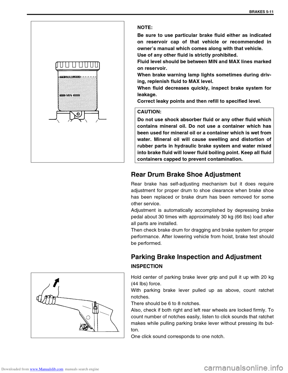
INSPECTION
Hold center of parking brake lever grip and pull it up with 20 kg
(44 Ibs) force.
With parking brake lever pulled up as above, count ratchet
notches.
There should be 6 to 8 notches.
Also, check if both right and left rear wheels are locked firmly. To
count number of notches easily, listen to click sounds that ratchet
makes while pulling parking brake lever without pressing its but-
ton.
One click sound corresponds to one notch.NOTE:
Be sure to use particular brake fluid either as indicated
on reservoir cap of that vehicle or recommended in
owner’s manual which comes along with that vehicle.
Use of any other fluid is strictly prohibited.
Fluid level should be between MIN and MAX lines marked
on reservoir.
When brake warning lamp lights sometimes during driv-
ing, replenish fluid to MAX level.
When fluid decreases quickly, inspect brake system for
leakage.
Correct leaky points and then refill to specified level.
CAUTION:
Do not use shock absorber fluid or any other fluid which
contains mineral oil. Do not use a container which has
been used for mineral oil or a container which is wet from
water. Mineral oil will cause swelling and distortion of
rubber parts in hydraulic brake system and water mixed
into brake fluid will lower fluid boiling point. Keep all fluid
containers capped to prevent contamination.
Page 278 of 687
Downloaded from www.Manualslib.com manuals search engine BRAKES 5-17
On-Vehicle Service
Air Bleeding of Brake System
Bleeding operation is necessary to remove air whenever it
entered hydraulic brake system.
Hydraulic lines of brake system consists of two separate lines,
one for front wheel brakes and the other for rear wheel brakes. Air
bleeding is necessary at right and left front wheel brakes, left rear
wheel brake and LSPV (if equipped), i.e. 3 (4 for vehicle with
LSPV) places in all.
Be sure to bleed air of brake system according to following proce-
dure when its oil hydraulic circuit has been disconnected.
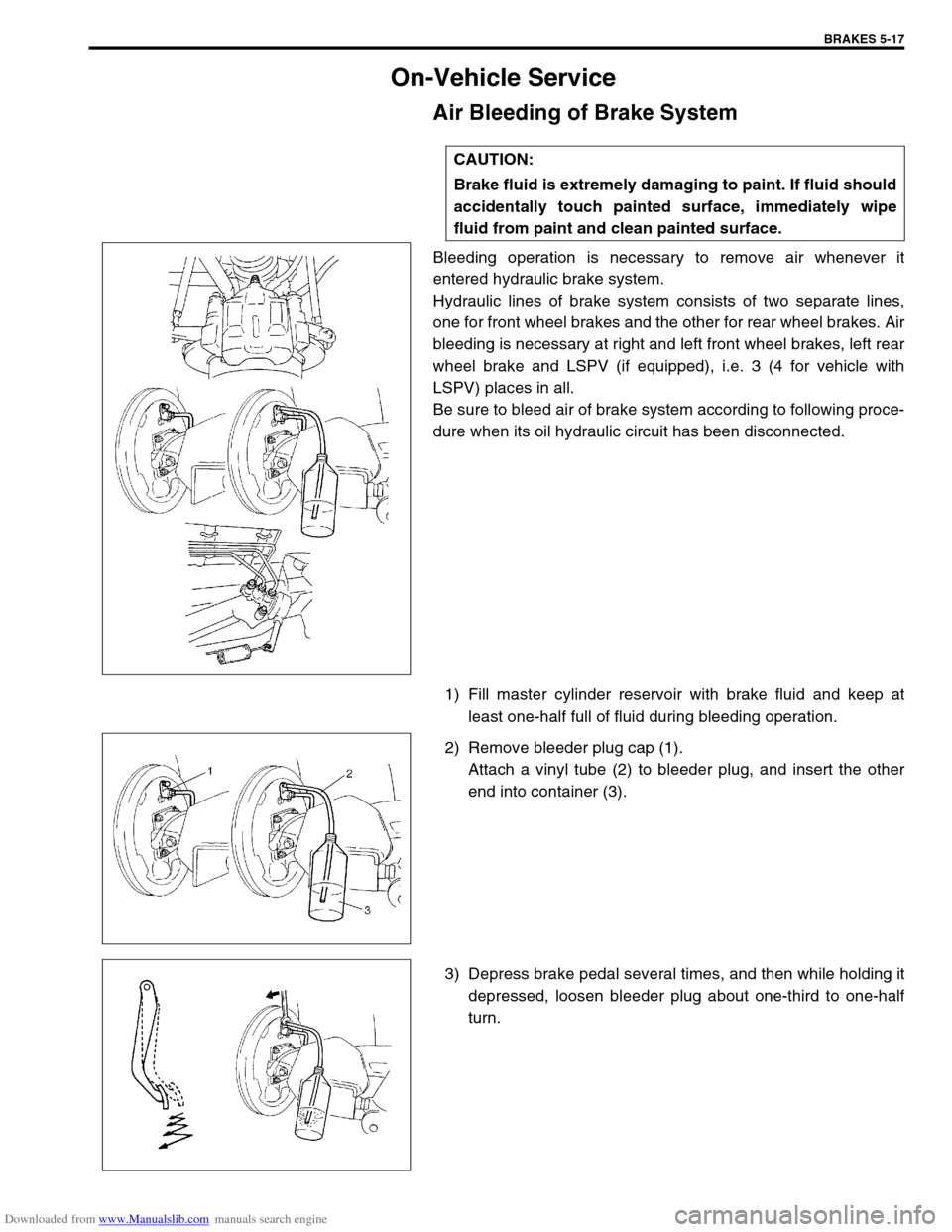
1) Fill master cylinder reservoir with brake fluid and keep at
least one-half full of fluid during bleeding operation.
2) Remove bleeder plug cap (1).
Attach a vinyl tube (2) to bleeder plug, and insert the other
end into container (3).
3) Depress brake pedal several times, and then while holding it
depressed, loosen bleeder plug about one-third to one-half
turn. CAUTION:
Brake fluid is extremely damaging to paint. If fluid should
accidentally touch painted surface, immediately wipe
fluid from paint and clean painted surface.
Page 291 of 687
Downloaded from www.Manualslib.com manuals search engine 5-30 BRAKES
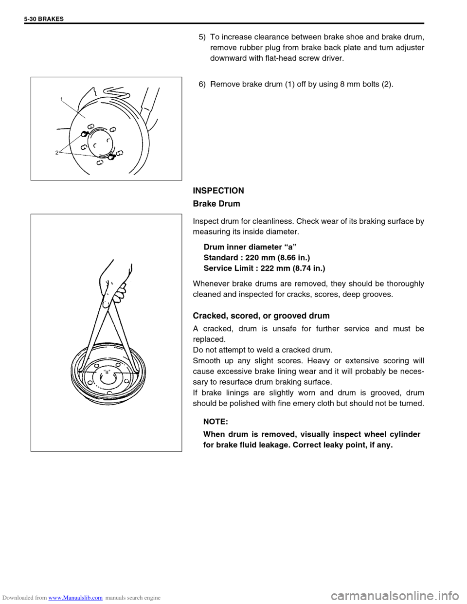
5) To increase clearance between brake shoe and brake drum,
remove rubber plug from brake back plate and turn adjuster
downward with flat-head screw driver.
6) Remove brake drum (1) off by using 8 mm bolts (2).
INSPECTION
Brake Drum
Inspect drum for cleanliness. Check wear of its braking surface by
measuring its inside diameter.
Drum inner diameter “a”
Standard : 220 mm (8.66 in.)
Service Limit : 222 mm (8.74 in.)
Whenever brake drums are removed, they should be thoroughly
cleaned and inspected for cracks, scores, deep grooves.
Cracked, scored, or grooved drum
A cracked, drum is unsafe for further service and must be
replaced.
Do not attempt to weld a cracked drum.
Smooth up any slight scores. Heavy or extensive scoring will
cause excessive brake lining wear and it will probably be neces-
sary to resurface drum braking surface.
If brake linings are slightly worn and drum is grooved, drum
should be polished with fine emery cloth but should not be turned.
NOTE:
When drum is removed, visually inspect wheel cylinder
for brake fluid leakage. Correct leaky point, if any.
Page 292 of 687
Downloaded from www.Manualslib.com manuals search engine BRAKES 5-31
Brake Shoe
Where lining is worn out beyond service limit, replace shoe.
If one of brake linings is to service limit, all linings must be
replaced at the same time.
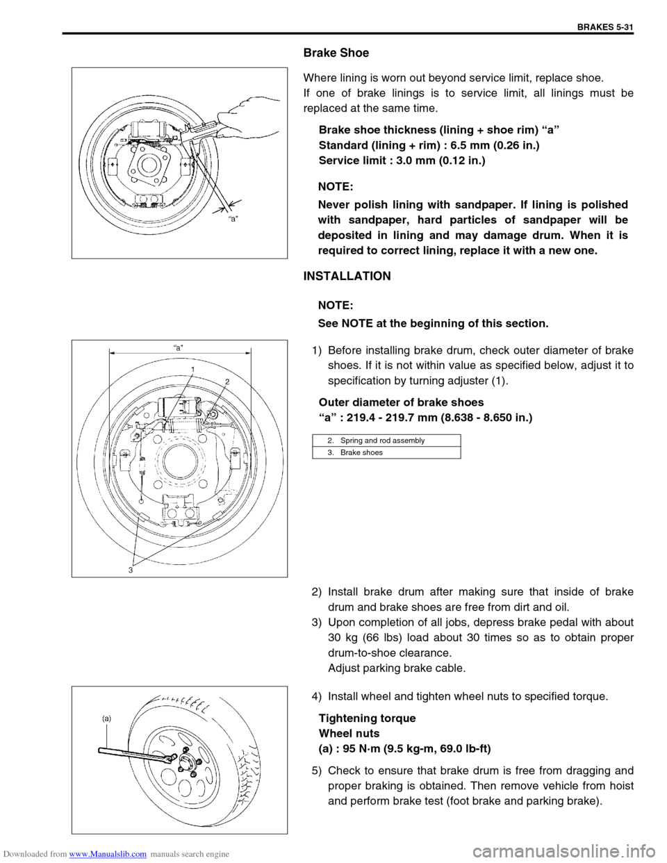
Brake shoe thickness (lining + shoe rim) “a”
Standard (lining + rim) : 6.5 mm (0.26 in.)
Service limit : 3.0 mm (0.12 in.)
INSTALLATION
1) Before installing brake drum, check outer diameter of brake
shoes. If it is not within value as specified below, adjust it to
specification by turning adjuster (1).
Outer diameter of brake shoes
“a” : 219.4 - 219.7 mm (8.638 - 8.650 in.)
2) Install brake drum after making sure that inside of brake
drum and brake shoes are free from dirt and oil.
3) Upon completion of all jobs, depress brake pedal with about
30 kg (66 lbs) load about 30 times so as to obtain proper
drum-to-shoe clearance.
Adjust parking brake cable.
4) Install wheel and tighten wheel nuts to specified torque.
Tightening torque
Wheel nuts
(a) : 95 N·m (9.5 kg-m, 69.0 lb-ft)
5) Check to ensure that brake drum is free from dragging and
proper braking is obtained. Then remove vehicle from hoist
and perform brake test (foot brake and parking brake). NOTE:
Never polish lining with sandpaper. If lining is polished
with sandpaper, hard particles of sandpaper will be
deposited in lining and may damage drum. When it is
required to correct lining, replace it with a new one.
NOTE:
See NOTE at the beginning of this section.
2. Spring and rod assembly
3. Brake shoes
Page 315 of 687

Downloaded from www.Manualslib.com manuals search engine 5-54 BRAKES
Tightening Torque Specifications
Required Service Material
Fastening partTightening torque
Nm kg-m lb-ft
Brake caliper carrier bolt 85 8.5 61.5
Brake caliper pin bolt 22 2.2 16.0
Front brake flexible hose bolt 23 2.3 17.0
Rear brake back plate nut 23 2.3 17.0
Master cylinder nut 13 1.3 9.5
Booster nut 13 1.3 9.5
Brake pipe 5-way 4-way joint bolt 11 1.1 8.0
Brake pipe flare nut 16 1.6 12.0
LSPV bolt/P valve bolt 25 2.5 18.0
Brake bleeder plugFront caliper 11 1.1 8.0
Rear wheel cylinder, LSPV 8 0.8 6.0
Wheel nut 95 9.5 69.0
Hose bracket bolt 11 1.1 8.0
Booster clevis nut 25 2.5 18.0
Stop light switch lock nut 6.5 0.65 4.7
Parking brake lever bolt 23 2.3 17.0
Wheel cylinder mounting bolt 9 0.9 6.5
Piston stopper bolt 10 1.0 7.5
LSPV adjust bolt 25 2.5 18.0
Material Recommended SUZUKI products Use
Brake fluid Indicated on reservoir tank cap or
described in owner’s manual of vehi-
cleTo fill master cylinder reservoir.
To clean and apply to inner parts of master
cylinder caliper and wheel cylinder when they
are disassembled.
Water tight sealant SEALING COMPOUND 366E
99000-31090To apply to mating surfaces of brake back
plate and rear wheel cylinder.
Sealant SUZUKI BOND NO. 1215
99000-31110To apply to mating surfaces of brake back
plate and rear axle housing.
To apply to mating surfaces of brake back
plate and rear wheel bearing retainer.