SUZUKI JIMNY 2005 3.G Service Workshop Manual
Manufacturer: SUZUKI, Model Year: 2005, Model line: JIMNY, Model: SUZUKI JIMNY 2005 3.GPages: 687, PDF Size: 13.38 MB
Page 461 of 687

Downloaded from www.Manualslib.com manuals search engine 6-104 ENGINE GENERAL INFORMATION AND DIAGNOSIS
DTC P1570 (DTC No.21) ABS Signal Circuit Malfunction
CIRCUIT DESCRIPTION
DTC CONFIRMATION PROCEDURE
1) Clear DTC, start engine and keep it at idle for 1 min.
2) Select “DTC” mode on scan tool and check DTC.
INSPECTION
DTC DETECTING CONDITION POSSIBLE CAUSE
ABS signal input is low when engine start.ABS signal circuit short to ground
ABS control module
Step Action Yes No
1Was “Engine Diag. Flow Table” performed? Go to Step 2. Go to “Engine Diag. Flow
Table”.
2 1) With the ignition switch ON position, check
voltage between E17-12 terminal of ECM
coupler and ground.
Is voltage within 10 – 14 V?Intermittent trouble.
If OK, substitute a known-
good ECM and recheck.Go to Step 3.
3 1) Check “G” wire for shorted to ground circuit.
Is “G” wire in good condition?Go to Step 4. Repair or replace.
4 1) Disconnect coupler of ABS control module.
2) Clear DTC.
3) Start engine and check DTC.
Is DTC P1570 (No.21) detected?Substitute a known-good
ECM and recheck.Substitute a known-good
ABS control module and
recheck.
Page 462 of 687

Downloaded from www.Manualslib.com manuals search engine ENGINE GENERAL INFORMATION AND DIAGNOSIS 6-105
DTC P1600 Serial Communication Problem Between ECM and TCM
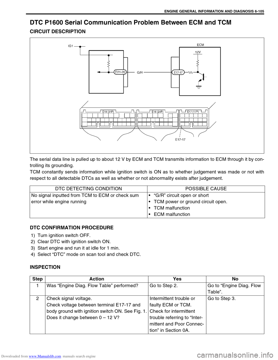
CIRCUIT DESCRIPTION
The serial data line is pulled up to about 12 V by ECM and TCM transmits information to ECM through it by con-
trolling its grounding.
TCM constantly sends information while ignition switch is ON as to whether judgement was made or not with
respect to all detectable DTCs as well as whether or not abnormality exists after judgement.
DTC CONFIRMATION PROCEDURE
1) Turn ignition switch OFF.
2) Clear DTC with ignition switch ON.
3) Start engine and run it at idle for 1 min.
4) Select “DTC” mode on scan tool and check DTC.
INSPECTION
DTC DETECTING CONDITION POSSIBLE CAUSE
No signal inputted from TCM to ECM or check sum
error while engine running“G/R” circuit open or short
TCM power or ground circuit open.
TCM malfunction
ECM malfunction
Step Action Yes No
1Was “Engine Diag. Flow Table” performed? Go to Step 2. Go to “Engine Diag. Flow
Table”.
2 Check signal voltage.
Check voltage between terminal E17-17 and
body ground with ignition switch ON. See Fig. 1.
Does it change between 0 – 12 V?Intermittent trouble or
faulty ECM or TCM.
Check for intermittent
trouble referring to “Inter-
mittent and Poor Connec-
tion” in Section 0A.Go to Step 3.
Page 463 of 687
![SUZUKI JIMNY 2005 3.G Service Workshop Manual Downloaded from www.Manualslib.com manuals search engine 6-106 ENGINE GENERAL INFORMATION AND DIAGNOSIS
[A] Fig. 1 for Step 2 / [B] Fig. 2 for Step 43 Is it about 12 V at Step 2?“B/R” wire open, p SUZUKI JIMNY 2005 3.G Service Workshop Manual Downloaded from www.Manualslib.com manuals search engine 6-106 ENGINE GENERAL INFORMATION AND DIAGNOSIS
[A] Fig. 1 for Step 2 / [B] Fig. 2 for Step 43 Is it about 12 V at Step 2?“B/R” wire open, p](/img/20/7588/w960_7588-462.png)
Downloaded from www.Manualslib.com manuals search engine 6-106 ENGINE GENERAL INFORMATION AND DIAGNOSIS
[A] Fig. 1 for Step 2 / [B] Fig. 2 for Step 43 Is it about 12 V at Step 2?“B/R” wire open, poor
E21-11 connection or
TCM power or ground cir-
cuit open.
If wires and connections
are OK, substitute a
known-good TCM and
recheck.Go to Step 4.
4 Check signal circuit.
1) Disconnect TCM coupler with ignition switch
OFF.
2) Check voltage between E21-20 terminal
and body ground with ignition switch ON.
See Fig. 2.
Is it about 12 V?Check TCM power and
ground circuit for open.
If OK, substitute a known-
good TCM and recheck.“B/R” wire shorted to
ground or poor E17-17
terminal connection.
If wire and connection are
OK, substitute a known-
good ECM and recheck. Step Action Yes No
Page 464 of 687

Downloaded from www.Manualslib.com manuals search engine ENGINE GENERAL INFORMATION AND DIAGNOSIS 6-107
DTC P1717 A/T Drive Range (Park / Neutral Position) Signal Circuit Malfunc-
tion
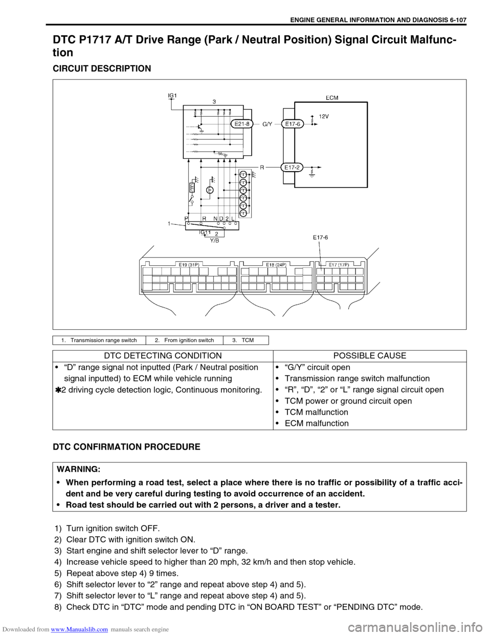
CIRCUIT DESCRIPTION
DTC CONFIRMATION PROCEDURE
1) Turn ignition switch OFF.
2) Clear DTC with ignition switch ON.
3) Start engine and shift selector lever to “D” range.
4) Increase vehicle speed to higher than 20 mph, 32 km/h and then stop vehicle.
5) Repeat above step 4) 9 times.
6) Shift selector lever to “2” range and repeat above step 4) and 5).
7) Shift selector lever to “L” range and repeat above step 4) and 5).
8) Check DTC in “DTC” mode and pending DTC in “ON BOARD TEST” or “PENDING DTC” mode.
1. Transmission range switch 2. From ignition switch 3. TCM
DTC DETECTING CONDITION POSSIBLE CAUSE
“D” range signal not inputted (Park / Neutral position
signal inputted) to ECM while vehicle running
✱
✱✱ ✱2 driving cycle detection logic, Continuous monitoring.“G/Y” circuit open
Transmission range switch malfunction
“R”, “D”, “2” or “L” range signal circuit open
TCM power or ground circuit open
TCM malfunction
ECM malfunction
WARNING:
When performing a road test, select a place where there is no traffic or possibility of a traffic acci-
dent and be very careful during testing to avoid occurrence of an accident.
Road test should be carried out with 2 persons, a driver and a tester.
Page 465 of 687
![SUZUKI JIMNY 2005 3.G Service Workshop Manual Downloaded from www.Manualslib.com manuals search engine 6-108 ENGINE GENERAL INFORMATION AND DIAGNOSIS
INSPECTION
[A] Fig. 1 for Step 3 / [B] Fig. 2 for Step 4 / [C] Fig. 3 for Step 6Step Action Yes SUZUKI JIMNY 2005 3.G Service Workshop Manual Downloaded from www.Manualslib.com manuals search engine 6-108 ENGINE GENERAL INFORMATION AND DIAGNOSIS
INSPECTION
[A] Fig. 1 for Step 3 / [B] Fig. 2 for Step 4 / [C] Fig. 3 for Step 6Step Action Yes](/img/20/7588/w960_7588-464.png)
Downloaded from www.Manualslib.com manuals search engine 6-108 ENGINE GENERAL INFORMATION AND DIAGNOSIS
INSPECTION
[A] Fig. 1 for Step 3 / [B] Fig. 2 for Step 4 / [C] Fig. 3 for Step 6Step Action Yes No
1Was “Engine Diag. Flow Table” performed? Go to Step 2. Go to “Engine Diag. Flow
Table”.
2 Is SUZUKI scan tool available? Go to Step 3. Go to Step 4.
3 Check PNP signal (“D” range signal).
1) Connect SUZUKI scan tool to DLC with igni-
tion switch OFF. See Fig. 1.
2) Turn ignition switch ON and check PNP sig-
nal (“P/N” or “D” range) on display when
shifting selector lever to each range.
Is “D” range on display (Is 0 – 1 V indicated) no
matter which of “R”, “D”, “2” and “L” range posi-
tions selector lever may be at? See Table 1.Intermittent trouble or
faulty ECM. Check for
intermittent referring to
“Intermittent and Poor
Connection” in Section
0A.Go to Step 5.
4 Check PNP Signal (“D” range signal).
1) Turn ignition switch ON.
2) Check voltage at terminal E17-6 of ECM
connector connected. See Fig. 2.
Is “D” range on display (Is 0 – 1 V indicated) no
matter which of “R”, “D”, “2” and “L” range posi-
tions selector lever may be at? See Table 1.Intermittent trouble or
faulty ECM. Check for
intermittent referring to
“Intermittent and Poor
Connection” in Section
0A.Go to Step 5.
5Is “P/N” range on display (Is 10 – 14 V indi-
cated) when selector lever is at one of “R”, “D”,
“2” and “L” range positions only?Check transmission range
switch and circuits refer-
ring to Section 7B.Go to Step 6.
6 Check PNP signal circuit.
1) Turn ignition switch OFF.
2) Disconnect TCM connectors.
3) Check for proper connection to TCM at ter-
minal E21-5.
4) If OK, then check voltage at terminal E21-8
in TCM connector disconnected, with igni-
tion switch ON. See Fig. 3
Is it 10 – 14 V?“Y/B” circuit open, poor
transmission range sen-
sor connector connec-
tion, select cable
maladjusted, transmis-
sion range sensor malad-
justed or transmission
range sensor malfunction.
If all above are OK, sub-
stitute a known-good TCM
and recheck.“G/Y” circuit open or poor
E17-6 connection.
If wire and connection are
OK, substitute a known-
good ECM and recheck.
Page 466 of 687
![SUZUKI JIMNY 2005 3.G Service Workshop Manual Downloaded from www.Manualslib.com manuals search engine ENGINE GENERAL INFORMATION AND DIAGNOSIS 6-109
[D] Table 1 for Step 3 and 4
Table B-1 Fuel Injector Circuit Check
INSPECTION
Scan tool voltmete SUZUKI JIMNY 2005 3.G Service Workshop Manual Downloaded from www.Manualslib.com manuals search engine ENGINE GENERAL INFORMATION AND DIAGNOSIS 6-109
[D] Table 1 for Step 3 and 4
Table B-1 Fuel Injector Circuit Check
INSPECTION
Scan tool voltmete](/img/20/7588/w960_7588-465.png)
Downloaded from www.Manualslib.com manuals search engine ENGINE GENERAL INFORMATION AND DIAGNOSIS 6-109
[D] Table 1 for Step 3 and 4
Table B-1 Fuel Injector Circuit Check
INSPECTION
Scan tool voltmeter
SUZUKI SCAN TOOL
DISPLAYVOLTAGE AT E17-6
Selector lever
position“P” and “N” range P/N range 10 – 14V
“R”, “D”, “2” and “L” range D range 0 – 1V
Step Action Yes No
1Was “Engine Diag. Flow Table” performed? Go to Step 2. Go to “Engine Diag. Flow
Table”.
2 Check Injector for Operating Sound.
Using sound scope, check each injector for
operating sound at engine cranking.
Do all 4 injector make operating sound?Fuel injector circuit is in
good condition.Go to Step 3.
3 Dose none of 4 injectors make operating sound
at Step 2?Go to Step 4. Check coupler connec-
tion and wire harness of
injector not making oper-
ating sound and injector
itself (Refer to Section
6E).
4 Check power circuit of injectors for open and
short.
Is it normal?Check all 4 injectors for
resistance respectively.
If resistance is OK, substi-
tute a known-good ECM
and recheck.Power circuit open or
short.
Page 467 of 687

Downloaded from www.Manualslib.com manuals search engine 6-110 ENGINE GENERAL INFORMATION AND DIAGNOSIS
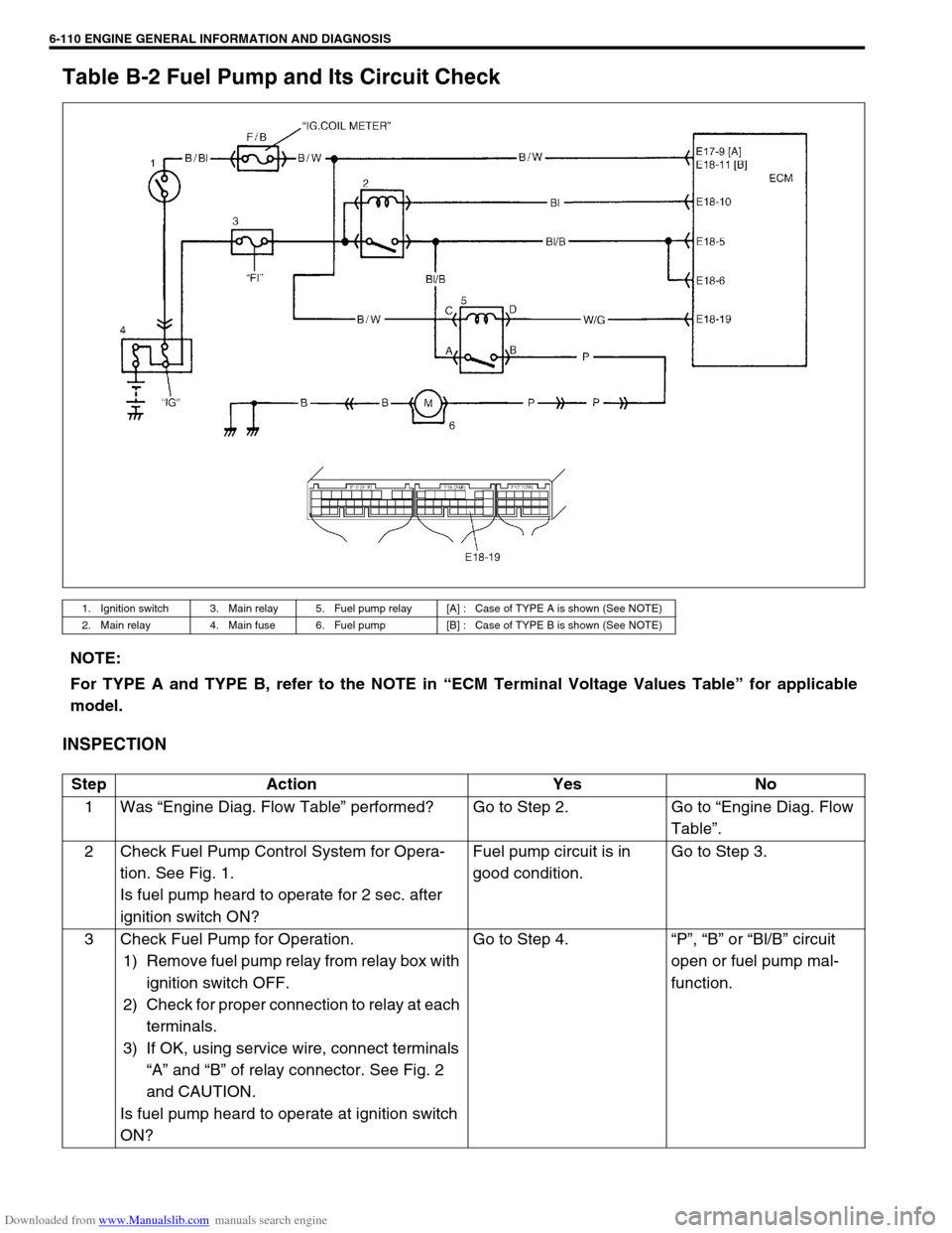
Table B-2 Fuel Pump and Its Circuit Check
INSPECTION
1. Ignition switch 3. Main relay 5. Fuel pump relay [A] : Case of TYPE A is shown (See NOTE)
2. Main relay 4. Main fuse 6. Fuel pump [B] : Case of TYPE B is shown (See NOTE)
NOTE:
For TYPE A and TYPE B, refer to the NOTE in “ECM Terminal Voltage Values Table” for applicable
model.
Step Action Yes No
1Was “Engine Diag. Flow Table” performed? Go to Step 2. Go to “Engine Diag. Flow
Table”.
2 Check Fuel Pump Control System for Opera-
tion. See Fig. 1.
Is fuel pump heard to operate for 2 sec. after
ignition switch ON?Fuel pump circuit is in
good condition.Go to Step 3.
3 Check Fuel Pump for Operation.
1) Remove fuel pump relay from relay box with
ignition switch OFF.
2) Check for proper connection to relay at each
terminals.
3) If OK, using service wire, connect terminals
“A” and “B” of relay connector. See Fig. 2
and CAUTION.
Is fuel pump heard to operate at ignition switch
ON?Go to Step 4.“P”, “B” or “Bl/B” circuit
open or fuel pump mal-
function.
Page 468 of 687
![SUZUKI JIMNY 2005 3.G Service Workshop Manual Downloaded from www.Manualslib.com manuals search engine ENGINE GENERAL INFORMATION AND DIAGNOSIS 6-111
[A] Fig. 1 for Step 2 / [B] Fig. 2 for Step 3 / [C] Fig. 3 for Step 44 Check Fuel Pump Relay for SUZUKI JIMNY 2005 3.G Service Workshop Manual Downloaded from www.Manualslib.com manuals search engine ENGINE GENERAL INFORMATION AND DIAGNOSIS 6-111
[A] Fig. 1 for Step 2 / [B] Fig. 2 for Step 3 / [C] Fig. 3 for Step 44 Check Fuel Pump Relay for](/img/20/7588/w960_7588-467.png)
Downloaded from www.Manualslib.com manuals search engine ENGINE GENERAL INFORMATION AND DIAGNOSIS 6-111
[A] Fig. 1 for Step 2 / [B] Fig. 2 for Step 3 / [C] Fig. 3 for Step 44 Check Fuel Pump Relay for Operation.
1) Check resistance between each two termi-
nals of fuel pump relay. See Fig.3.
Fuel pump relay resistance
Between terminals “A” and “B” : Infinity
Between terminals “C” and “D”: 100 – 150
Ω
ΩΩ Ω
2) Check that there is continuity between ter-
minals “A” and “B” when battery is con-
nected to terminals “C” and “D”. See Fig. 3.
Is fuel pump relay in good condition?“W/G” circuit open or poor
E18-19 connection.
If wire and connection are
OK, substitute a known-
good ECM and recheck.Replace fuel pump
relay. Step Action Yes No
CAUTION:
Check to make sure that connection is made between correct terminals. Wrong connection can cause
damage to ECM, wire harness, etc.
Page 469 of 687

Downloaded from www.Manualslib.com manuals search engine 6-112 ENGINE GENERAL INFORMATION AND DIAGNOSIS
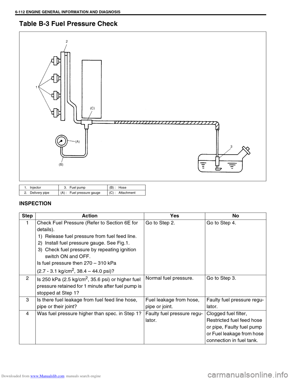
Table B-3 Fuel Pressure Check
INSPECTION
1. Injector 3. Fuel pump (B) : Hose
2. Delivery pipe (A) : Fuel pressure gauge (C) : Attachment
Step Action Yes No
1 Check Fuel Pressure (Refer to Section 6E for
details).
1) Release fuel pressure from fuel feed line.
2) Install fuel pressure gauge. See Fig.1.
3) Check fuel pressure by repeating ignition
switch ON and OFF.
Is fuel pressure then 270 – 310 kPa
(2.7 - 3.1 kg/cm
2, 38.4 – 44.0 psi)?Go to Step 2. Go to Step 4.
2
Is 250 kPa (2.5 kg/cm
2, 35.6 psi) or higher fuel
pressure retained for 1 minute after fuel pump is
stopped at Step 1?Normal fuel pressure. Go to Step 3.
3 Is there fuel leakage from fuel feed line hose,
pipe or their joint?Fuel leakage from hose,
pipe or joint.Faulty fuel pressure regu-
lator.
4 Was fuel pressure higher than spec. in Step 1? Faulty fuel pressure regu-
lator.Clogged fuel filter,
Restricted fuel feed hose
or pipe, Faulty fuel pump
or Fuel leakage from hose
connection in fuel tank.
Page 470 of 687

Downloaded from www.Manualslib.com manuals search engine ENGINE GENERAL INFORMATION AND DIAGNOSIS 6-113
Fig. 1 for Step 1
Special tool
(A) : 09912-58441
(B) : 09912-58431
(C) : 09912-58490