light SUZUKI SWIFT 2000 1.G RG413 Service User Guide
[x] Cancel search | Manufacturer: SUZUKI, Model Year: 2000, Model line: SWIFT, Model: SUZUKI SWIFT 2000 1.GPages: 698, PDF Size: 16.01 MB
Page 73 of 698
1B-8 AIR CONDITIONING (OPTIONAL)
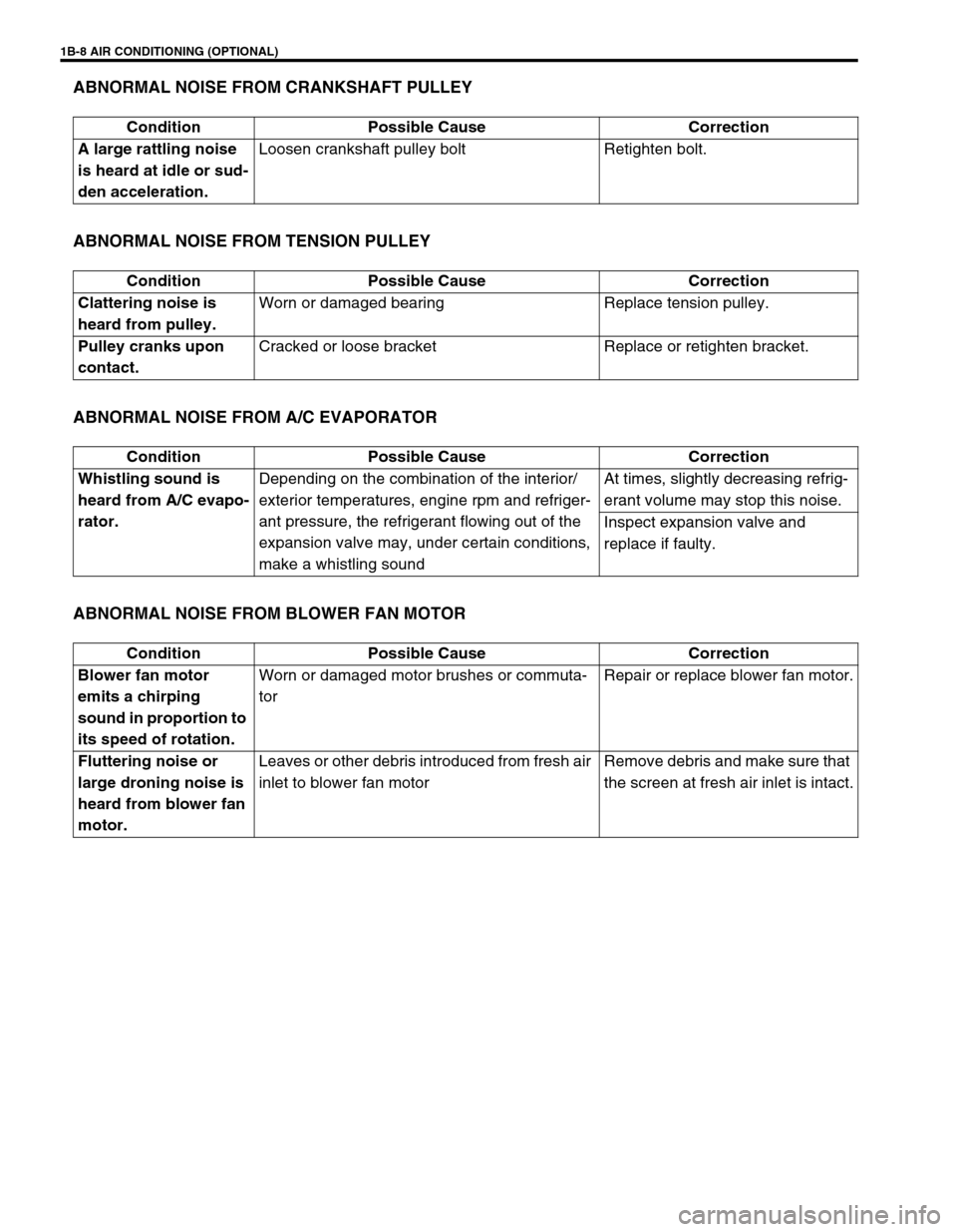
ABNORMAL NOISE FROM CRANKSHAFT PULLEY
ABNORMAL NOISE FROM TENSION PULLEY
ABNORMAL NOISE FROM A/C EVAPORATOR
ABNORMAL NOISE FROM BLOWER FAN MOTOR
Condition Possible Cause Correction
A large rattling noise
is heard at idle or sud-
den acceleration.Loosen crankshaft pulley bolt Retighten bolt.
Condition Possible Cause Correction
Clattering noise is
heard from pulley.Worn or damaged bearing Replace tension pulley.
Pulley cranks upon
contact.Cracked or loose bracket Replace or retighten bracket.
Condition Possible Cause Correction
Whistling sound is
heard from A/C evapo-
rator.Depending on the combination of the interior/
exterior temperatures, engine rpm and refriger-
ant pressure, the refrigerant flowing out of the
expansion valve may, under certain conditions,
make a whistling soundAt times, slightly decreasing refrig-
erant volume may stop this noise.
Inspect expansion valve and
replace if faulty.
Condition Possible Cause Correction
Blower fan motor
emits a chirping
sound in proportion to
its speed of rotation.Worn or damaged motor brushes or commuta-
torRepair or replace blower fan motor.
Fluttering noise or
large droning noise is
heard from blower fan
motor.Leaves or other debris introduced from fresh air
inlet to blower fan motorRemove debris and make sure that
the screen at fresh air inlet is intact.
Page 78 of 698
AIR CONDITIONING (OPTIONAL) 1B-13
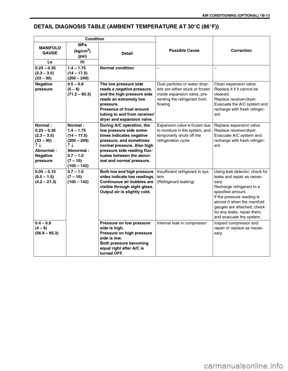
DETAIL DIAGNOSIS TABLE (AMBIENT TEMPERATURE AT 30°C (86°F))
Condition
Possible Cause Correction MANIFOLD
GAUGEMPa
(kg/cm
2)
(psi)Detail
Lo Hi
0.23 – 0.35
(2.3 – 3.5)
(33 – 50)1.4 – 1.75
(14 – 17.5)
(200 – 249)Normal condition––
Negative
pressure0.5 – 0.6
(5 – 6)
(71.2 – 85.3)The low pressure side
reads a negative pressure,
and the high pressure side
reads an extremely low
pressure.
Presence of frost around
tubing to and from receiver/
dryer and expansion valve.Dust particles or water drop-
lets are either stuck or frozen
inside expansion valve, pre-
venting the refrigerant from
flowingClean expansion valve.
Replace it if it cannot be
cleaned.
Replace receiver/dryer.
Evacuate the A/C system and
recharge with fresh refriger-
ant.
Normal :
0.23 – 0.35
(2.3 – 3.5)
(33 – 50)
↑ ↓
↑ ↓↑ ↓ ↑ ↓
Abnormal :
Negative
pressureNormal :
1.4 – 1.75
(14 – 17.5)
(200 – 249)
↑ ↓
↑ ↓↑ ↓ ↑ ↓
Abnormal :
0.7 – 1.0
(7 – 10)
(100 – 142)During A/C operation, the
low pressure side some-
times indicates negative
pressure, and sometimes
normal pressure. Also high
pressure side reading fluc-
tuates between the abnor-
mal and normal pressure.Expansion valve is frozen due
to moisture in the system, and
temporarily shuts off the
refrigeration cycleReplace expansion valve.
Replace receiver/dryer.
Evacuate A/C system and
recharge with fresh refriger-
ant.
0.05 – 0.15
(0.5 – 1.5)
(4.2 – 21.3)0.7 – 1.0
(7 – 10)
(100 – 142)Both low and high pressure
sides indicate low readings.
Continuous air bubbles are
visible through sight glass.
Output air is slightly cold.Insufficient refrigerant in sys-
tem
(Refrigerant leaking)Using leak detector, check for
leaks and repair as neces-
sary.
Recharge refrigerant to a
specified amount.
If the pressure reading is
almost 0 when the manifold
gauges are attached, check
for any leaks, repair them,
and evacuate the system.
0.4 – 0.6
(4 – 6)
(56.9 – 85.3)Pressure on low pressure
side is high.
Pressure on high pressure
side is low.
Both pressure becoming
equal right after A/C is
turned OFF.Internal leak in compressor Inspect compressor and
repair or replace as neces-
sary.
Page 81 of 698
1B-16 AIR CONDITIONING (OPTIONAL)
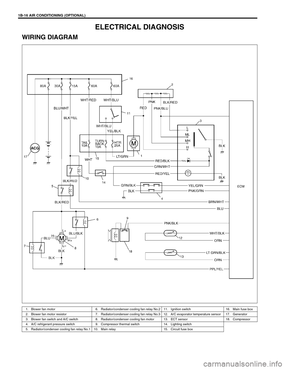
ELECTRICAL DIAGNOSIS
WIRING DIAGRAM
1. Blower fan motor 6. Radiator/condenser cooling fan relay No.2 11. Ignition switch 16. Main fuse box
2. Blower fan motor resistor 7. Radiator/condenser cooling fan relay No.3 12. A/C evaporator temperature sensor 17. Generator
3. Blower fan switch and A/C switch 8. Radiator/condenser cooling fan motor 13. ECT sensor 18. Compressor
4. A/C refrigerant pressure switch 9. Compressor thermal switch 14. Lighting switch
5. Radiator/condenser cooling fan relay No.1 10. Main relay 15. Circuit fuse box
Page 85 of 698
1B-20 AIR CONDITIONING (OPTIONAL)
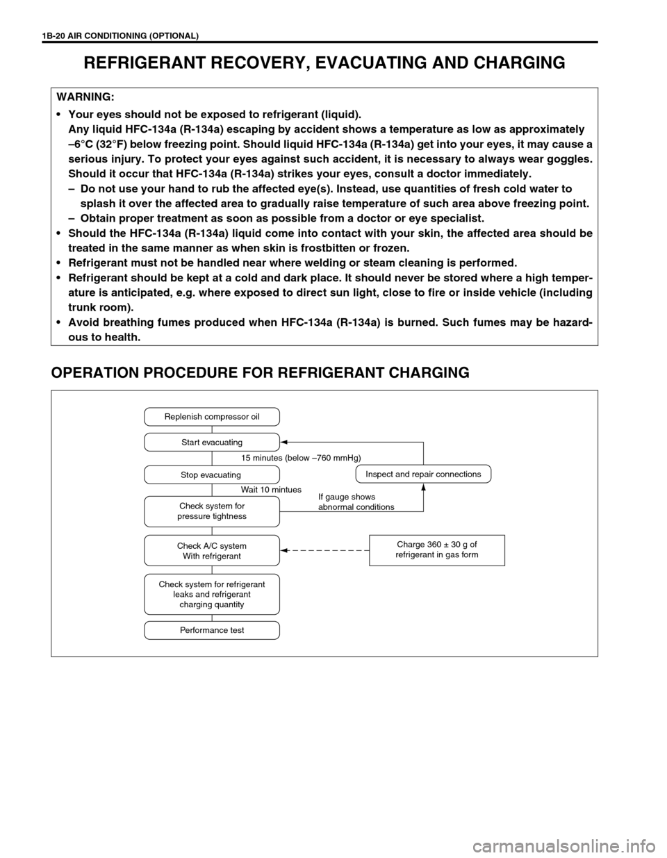
REFRIGERANT RECOVERY, EVACUATING AND CHARGING
OPERATION PROCEDURE FOR REFRIGERANT CHARGING
WARNING:
Your eyes should not be exposed to refrigerant (liquid).
Any liquid HFC-134a (R-134a) escaping by accident shows a temperature as low as approximately
–6°C (32°F) below freezing point. Should liquid HFC-134a (R-134a) get into your eyes, it may cause a
serious injury. To protect your eyes against such accident, it is necessary to always wear goggles.
Should it occur that HFC-134a (R-134a) strikes your eyes, consult a doctor immediately.
– Do not use your hand to rub the affected eye(s). Instead, use quantities of fresh cold water to
splash it over the affected area to gradually raise temperature of such area above freezing point.
– Obtain proper treatment as soon as possible from a doctor or eye specialist.
Should the HFC-134a (R-134a) liquid come into contact with your skin, the affected area should be
treated in the same manner as when skin is frostbitten or frozen.
Refrigerant must not be handled near where welding or steam cleaning is performed.
Refrigerant should be kept at a cold and dark place. It should never be stored where a high temper-
ature is anticipated, e.g. where exposed to direct sun light, close to fire or inside vehicle (including
trunk room).
Avoid breathing fumes produced when HFC-134a (R-134a) is burned. Such fumes may be hazard-
ous to health.
Replenish compressor oil
Start evacuating
Inspect and repair connections
Charge 360 ± 30 g of
refrigerant in gas form Stop evacuating 15 minutes (below –760 mmHg)
Wait 10 mintues
If gauge shows
abnormal conditions Check system for
pressure tightness
Check A/C system
With refrigerant
Check system for refrigerant
leaks and refrigerant
charging quantity
Performance test
Page 90 of 698
AIR CONDITIONING (OPTIONAL) 1B-25
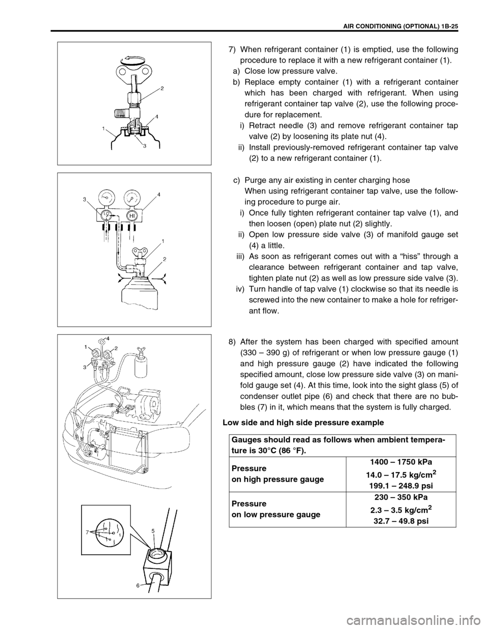
7) When refrigerant container (1) is emptied, use the following
procedure to replace it with a new refrigerant container (1).
a) Close low pressure valve.
b) Replace empty container (1) with a refrigerant container
which has been charged with refrigerant. When using
refrigerant container tap valve (2), use the following proce-
dure for replacement.
i) Retract needle (3) and remove refrigerant container tap
valve (2) by loosening its plate nut (4).
ii) Install previously-removed refrigerant container tap valve
(2) to a new refrigerant container (1).
c) Purge any air existing in center charging hose
When using refrigerant container tap valve, use the follow-
ing procedure to purge air.
i) Once fully tighten refrigerant container tap valve (1), and
then loosen (open) plate nut (2) slightly.
ii) Open low pressure side valve (3) of manifold gauge set
(4) a little.
iii) As soon as refrigerant comes out with a “hiss” through a
clearance between refrigerant container and tap valve,
tighten plate nut (2) as well as low pressure side valve (3).
iv) Turn handle of tap valve (1) clockwise so that its needle is
screwed into the new container to make a hole for refriger-
ant flow.
8) After the system has been charged with specified amount
(330 – 390 g) of refrigerant or when low pressure gauge (1)
and high pressure gauge (2) have indicated the following
specified amount, close low pressure side valve (3) on mani-
fold gauge set (4). At this time, look into the sight glass (5) of
condenser outlet pipe (6) and check that there are no bub-
bles (7) in it, which means that the system is fully charged.
Low side and high side pressure example
Gauges should read as follows when ambient tempera-
ture is 30°C (86 °F).
Pressure
on high pressure gauge1400 – 1750 kPa
14.0 – 17.5 kg/cm
2
199.1 – 248.9 psi
Pressure
on low pressure gauge230 – 350 kPa
2.3 – 3.5 kg/cm
2
32.7 – 49.8 psi
Page 92 of 698
AIR CONDITIONING (OPTIONAL) 1B-27
ON-VEHICLE SERVICE
SERVICE PRECAUTION
When servicing air conditioning system, note the following instructions.
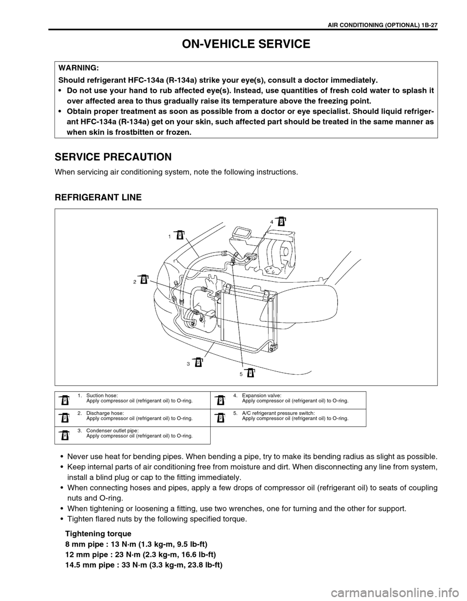
REFRIGERANT LINE
Never use heat for bending pipes. When bending a pipe, try to make its bending radius as slight as possible.
Keep internal parts of air conditioning free from moisture and dirt. When disconnecting any line from system,
install a blind plug or cap to the fitting immediately.
When connecting hoses and pipes, apply a few drops of compressor oil (refrigerant oil) to seats of coupling
nuts and O-ring.
When tightening or loosening a fitting, use two wrenches, one for turning and the other for support.
Tighten flared nuts by the following specified torque.
Tightening torque
8 mm pipe : 13 N·m (1.3 kg-m, 9.5 lb-ft)
12 mm pipe : 23 N·m (2.3 kg-m, 16.6 lb-ft)
14.5 mm pipe : 33 N·m (3.3 kg-m, 23.8 lb-ft) WARNING:
Should refrigerant HFC-134a (R-134a) strike your eye(s), consult a doctor immediately.
Do not use your hand to rub affected eye(s). Instead, use quantities of fresh cold water to splash it
over affected area to thus gradually raise its temperature above the freezing point.
Obtain proper treatment as soon as possible from a doctor or eye specialist. Should liquid refriger-
ant HFC-134a (R-134a) get on your skin, such affected part should be treated in the same manner as
when skin is frostbitten or frozen.
1. Suction hose:
Apply compressor oil (refrigerant oil) to O-ring.4. Expansion valve:
Apply compressor oil (refrigerant oil) to O-ring.
2. Discharge hose:
Apply compressor oil (refrigerant oil) to O-ring.5. A/C refrigerant pressure switch:
Apply compressor oil (refrigerant oil) to O-ring.
3. Condenser outlet pipe:
Apply compressor oil (refrigerant oil) to O-ring.
Page 101 of 698
1B-36 AIR CONDITIONING (OPTIONAL)
A/C SWITCH
REMOVAL AND INSTALLATION
Refer to “HEATER CONTROL ASSEMBLY” in Section 1A.
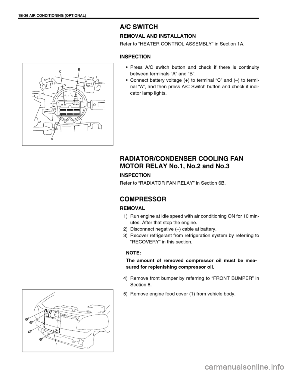
INSPECTION
Press A/C switch button and check if there is continuity
between terminals “A” and “B”.
Connect battery voltage (+) to terminal “C” and (–) to termi-
nal “A”, and then press A/C Switch button and check if indi-
cator lamp lights.
RADIATOR/CONDENSER COOLING FAN
MOTOR RELAY No.1, No.2 and No.3
INSPECTION
Refer to “RADIATOR FAN RELAY” in Section 6B.
COMPRESSOR
REMOVAL
1) Run engine at idle speed with air conditioning ON for 10 min-
utes. After that stop the engine.
2) Disconnect negative (–) cable at battery.
3) Recover refrigerant from refrigeration system by referring to
“RECOVERY” in this section.
4) Remove front bumper by referring to “FRONT BUMPER” in
Section 8.
5) Remove engine food cover (1) from vehicle body.
NOTE:
The amount of removed compressor oil must be mea-
sured for replenishing compressor oil.
Page 134 of 698
MANUAL RACK AND PINION 3B-13
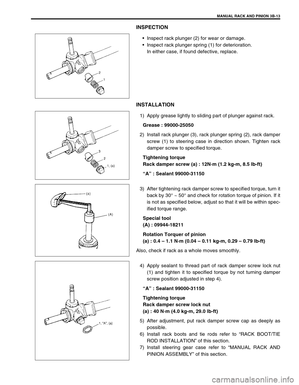
INSPECTION
Inspect rack plunger (2) for wear or damage.
Inspect rack plunger spring (1) for deterioration.
In either case, if found defective, replace.
INSTALLATION
1) Apply grease lightly to sliding part of plunger against rack.
Grease : 99000-25050
2) Install rack plunger (3), rack plunger spring (2), rack damper
screw (1) to steering case in direction shown. Tighten rack
damper screw to specified torque.
Tightening torque
Rack damper screw (a) : 12N·m (1.2 kg-m, 8.5 lb-ft)
“A” : Sealant 99000-31150
3) After tightening rack damper screw to specified torque, turn it
back by 30° ~ 50° and check for rotation torque of pinion. If it
is not as specified below, adjust so that it will be within spec-
ified torque range.
Special tool
(A) : 09944-18211
Rotation Torquer of pinion
(a) : 0.4 – 1.1 N·m (0.04 – 0.11 kg-m, 0.29 – 0.79 lb-ft)
Also, check if rack as a whole moves smoothly.
4) Apply sealant to thread part of rack damper screw lock nut
(1) and tighten it to specified torque by not turning damper
screw position adjusted in step 4).
“A” : Sealant 99000-31150
Tightening torque
Rack damper screw lock nut
(a) : 40 N·m (4.0 kg-m, 29.0 lb-ft)
5) After adjustment, put rack damper screw cap as deeply as
possible.
6) Install rack boots and tie rods refer to “RACK BOOT/TIE
ROD INSTALLATION” of this section.
7) Install steering gear case refer to “MANUAL RACK AND
PINION ASSEMBLY” of this section.
Page 140 of 698
MANUAL RACK AND PINION 3B-19
INSTALLATION
1) Apply grease lightly to entire inner surface of bushing.
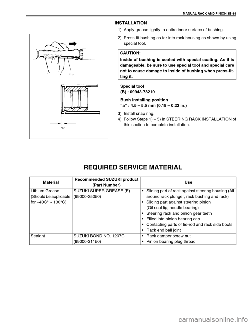
2) Press-fit bushing as far into rack housing as shown by using
special tool.
Special tool
(B) : 09943-78210
Bush installing position
“a” : 4.5 – 5.5 mm (0.18 – 0.22 in.)
3) Install snap ring.
4) Follow Steps 1) – 5) in STEERING RACK INSTALLATION of
this section to complete installation.
REQUIRED SERVICE MATERIAL
CAUTION:
Inside of bushing is coated with special coating. As it is
damageable, be sure to use special tool and special care
not to cause damage to inside of bushing when press-fit-
ting it.
MaterialRecommended SUZUKI product
(Part Number)Use
Lithium Grease
(Should be applicable
for –40C° ~ 130°C)SUZUKI SUPER GREASE (E)
(99000-25050)Sliding part of rack against steering housing (All
around rack plunger, rack bushing and rack)
Sliding part against steering pinion
(Oil seal lip, needle bearing)
Steering rack and pinion gear teeth
Filled into pinion bearing cap
Contacting parts of tie-rod and rack side boots
Rack end ball joint
Sealant SUZUKI BOND NO. 1207C
(99000-31150)Rack damper screw nut
Pinion bearing plug thread
Page 145 of 698
3B1-4 ELECTRICAL POWER STEERING (P/S) SYSTEM
DIAGNOSIS
The P/S system in this vehicle is controlled by P/S control module. P/S control module has an on-board diagnos-
tic system which detects a malfunction in this system.
When diagnosing troubles, be sure to have full understanding of the outline of “ON-BOARD DIAGNOSTIC SYS-
TEM” and each item in “PRECAUTION IN DIAGNOSING TROUBLE” and execute diagnosis according to “SYS-
TEM CHECK FLOW TABLE”.
ON-BOARD DIAGNOSTIC SYSTEM
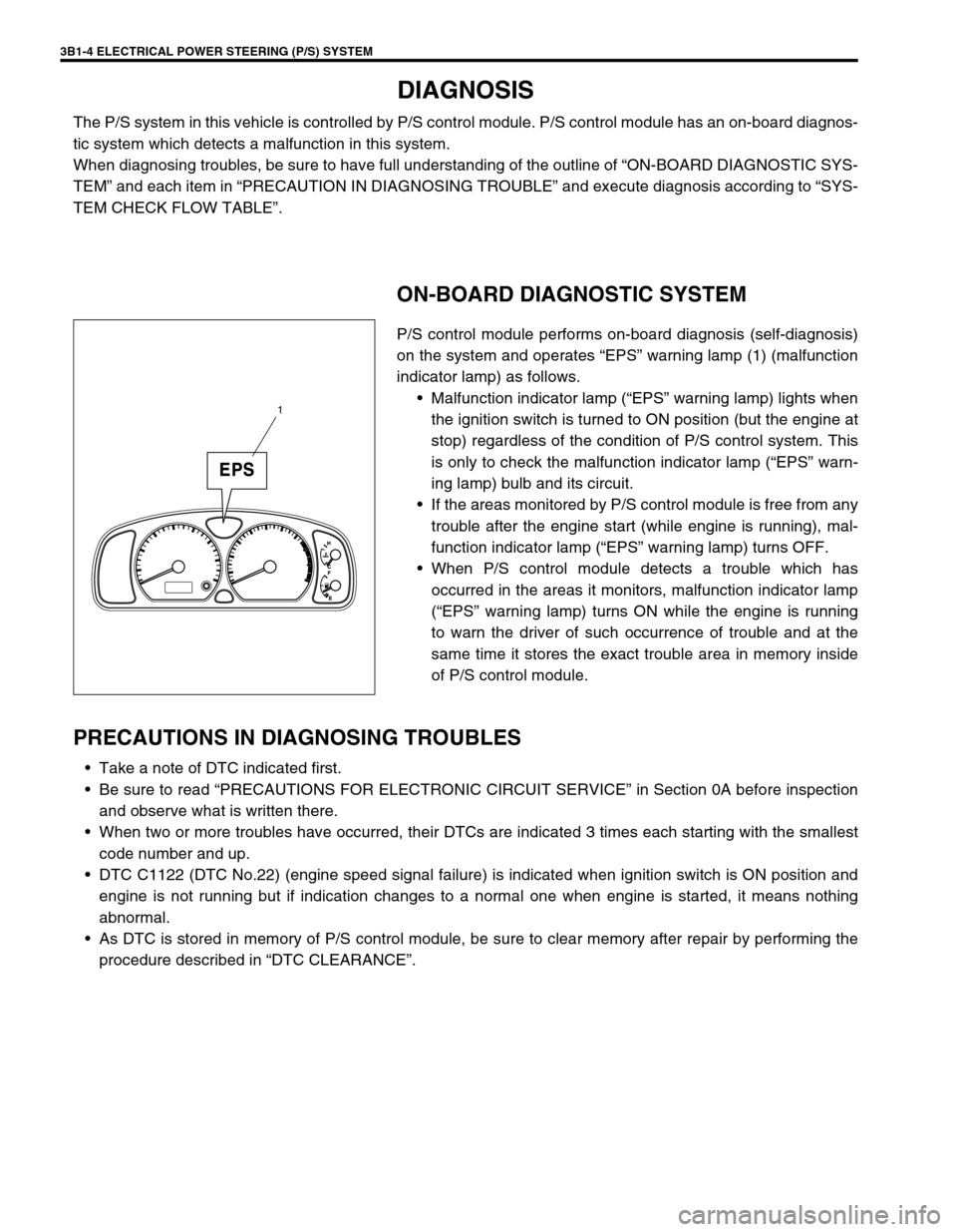
P/S control module performs on-board diagnosis (self-diagnosis)
on the system and operates “EPS” warning lamp (1) (malfunction
indicator lamp) as follows.
Malfunction indicator lamp (“EPS” warning lamp) lights when
the ignition switch is turned to ON position (but the engine at
stop) regardless of the condition of P/S control system. This
is only to check the malfunction indicator lamp (“EPS” warn-
ing lamp) bulb and its circuit.
If the areas monitored by P/S control module is free from any
trouble after the engine start (while engine is running), mal-
function indicator lamp (“EPS” warning lamp) turns OFF.
When P/S control module detects a trouble which has
occurred in the areas it monitors, malfunction indicator lamp
(“EPS” warning lamp) turns ON while the engine is running
to warn the driver of such occurrence of trouble and at the
same time it stores the exact trouble area in memory inside
of P/S control module.
PRECAUTIONS IN DIAGNOSING TROUBLES
Take a note of DTC indicated first.
Be sure to read “PRECAUTIONS FOR ELECTRONIC CIRCUIT SERVICE” in Section 0A before inspection
and observe what is written there.
When two or more troubles have occurred, their DTCs are indicated 3 times each starting with the smallest
code number and up.
DTC C1122 (DTC No.22) (engine speed signal failure) is indicated when ignition switch is ON position and
engine is not running but if indication changes to a normal one when engine is started, it means nothing
abnormal.
As DTC is stored in memory of P/S control module, be sure to clear memory after repair by performing the
procedure described in “DTC CLEARANCE”.
1